EP1288574A1 - Agencement de chambre de combustion - Google Patents
Agencement de chambre de combustion Download PDFInfo
- Publication number
- EP1288574A1 EP1288574A1 EP01121089A EP01121089A EP1288574A1 EP 1288574 A1 EP1288574 A1 EP 1288574A1 EP 01121089 A EP01121089 A EP 01121089A EP 01121089 A EP01121089 A EP 01121089A EP 1288574 A1 EP1288574 A1 EP 1288574A1
- Authority
- EP
- European Patent Office
- Prior art keywords
- combustion chamber
- turbine
- chamber arrangement
- individual
- arrangement according
- Prior art date
- Legal status (The legal status is an assumption and is not a legal conclusion. Google has not performed a legal analysis and makes no representation as to the accuracy of the status listed.)
- Withdrawn
Links
- 238000002485 combustion reaction Methods 0.000 title claims abstract description 91
- 230000007704 transition Effects 0.000 claims description 10
- 238000002156 mixing Methods 0.000 claims 1
- 238000001816 cooling Methods 0.000 description 26
- 239000012809 cooling fluid Substances 0.000 description 14
- 239000007789 gas Substances 0.000 description 14
- 239000002737 fuel gas Substances 0.000 description 4
- 230000000694 effects Effects 0.000 description 3
- 239000000446 fuel Substances 0.000 description 3
- 239000000203 mixture Substances 0.000 description 3
- QVGXLLKOCUKJST-UHFFFAOYSA-N atomic oxygen Chemical compound [O] QVGXLLKOCUKJST-UHFFFAOYSA-N 0.000 description 2
- 238000010276 construction Methods 0.000 description 2
- 239000001301 oxygen Substances 0.000 description 2
- 229910052760 oxygen Inorganic materials 0.000 description 2
- 238000011144 upstream manufacturing Methods 0.000 description 2
- 241001156002 Anthonomus pomorum Species 0.000 description 1
- 238000005352 clarification Methods 0.000 description 1
- 239000002826 coolant Substances 0.000 description 1
- 238000005562 fading Methods 0.000 description 1
- 239000012530 fluid Substances 0.000 description 1
- 238000010438 heat treatment Methods 0.000 description 1
Images

Classifications
-
- F—MECHANICAL ENGINEERING; LIGHTING; HEATING; WEAPONS; BLASTING
- F23—COMBUSTION APPARATUS; COMBUSTION PROCESSES
- F23R—GENERATING COMBUSTION PRODUCTS OF HIGH PRESSURE OR HIGH VELOCITY, e.g. GAS-TURBINE COMBUSTION CHAMBERS
- F23R3/00—Continuous combustion chambers using liquid or gaseous fuel
- F23R3/42—Continuous combustion chambers using liquid or gaseous fuel characterised by the arrangement or form of the flame tubes or combustion chambers
- F23R3/60—Support structures; Attaching or mounting means
-
- F—MECHANICAL ENGINEERING; LIGHTING; HEATING; WEAPONS; BLASTING
- F01—MACHINES OR ENGINES IN GENERAL; ENGINE PLANTS IN GENERAL; STEAM ENGINES
- F01D—NON-POSITIVE DISPLACEMENT MACHINES OR ENGINES, e.g. STEAM TURBINES
- F01D25/00—Component parts, details, or accessories, not provided for in, or of interest apart from, other groups
- F01D25/08—Cooling; Heating; Heat-insulation
- F01D25/14—Casings modified therefor
-
- F—MECHANICAL ENGINEERING; LIGHTING; HEATING; WEAPONS; BLASTING
- F23—COMBUSTION APPARATUS; COMBUSTION PROCESSES
- F23R—GENERATING COMBUSTION PRODUCTS OF HIGH PRESSURE OR HIGH VELOCITY, e.g. GAS-TURBINE COMBUSTION CHAMBERS
- F23R3/00—Continuous combustion chambers using liquid or gaseous fuel
- F23R3/002—Wall structures
-
- F—MECHANICAL ENGINEERING; LIGHTING; HEATING; WEAPONS; BLASTING
- F23—COMBUSTION APPARATUS; COMBUSTION PROCESSES
- F23R—GENERATING COMBUSTION PRODUCTS OF HIGH PRESSURE OR HIGH VELOCITY, e.g. GAS-TURBINE COMBUSTION CHAMBERS
- F23R3/00—Continuous combustion chambers using liquid or gaseous fuel
- F23R3/42—Continuous combustion chambers using liquid or gaseous fuel characterised by the arrangement or form of the flame tubes or combustion chambers
- F23R3/46—Combustion chambers comprising an annular arrangement of several essentially tubular flame tubes within a common annular casing or within individual casings
Definitions
- the invention relates to a combustion chamber arrangement for a gas turbine with a variety of in one, in one Individual combustion chambers leading to the annular space leading to the turbine space, with burners upstream of the individual combustion chambers are that with the individual combustion chambers through an outer casing are connected through.
- the invention further relates to a Gas turbine with such a combustion chamber arrangement.
- Such combustion chamber arrangements for gas turbines are in the state of the art.
- a mixture ignited in the burners from an oxygen-containing fuel gas and a fuel is burned in the combustion chambers and the expanding ones Hot gases are released through the transition sections of the individual combustion chambers in the direction of the turbine chamber and the ones inside Arrangement of guide vanes and rotor blades deflected.
- The are in the usually circular cylindrical built entrance sections of the individual combustion chambers generated hot gas flows with a circular cross section the transition sections into a hot gas stream with a circular segment Cross section transferred and finally to merged into a circular hot gas stream. This enters the turbine space through the annular gap and drives the blades of the gas turbine.
- Cooling fluid flows open on the individual combustion chambers over and creates a cooling effect.
- the cooling fluid flow is not directed and defined, which results in an overall lower cooling efficiency.
- such a design of the individual combustion chambers structurally simpler and requires less effort.
- the invention has for its object to further develop a combustion chamber arrangement of the type mentioned in such a way that the cooling efficiency can be increased considerably in the case of individual combustion chambers of simple design.
- At least one connecting piece which is arranged on a side of the turbine outer casing facing the turbine space and extends radially in the direction of the turbine space and at least partially surrounds a section of at least one individual combustion chamber while leaving a gap space.
- the arranged on the turbine outer casing according to the invention radially extending in the direction of the turbine space at least a nozzle surrounds one inside the turbine outer casing located section of at least one single combustion chamber and leaves between the wall of the single combustion chamber and the Trim a gap.
- a cooling fluid can enter this gap flow in and due to the defined flow channel cause more effective convective cooling in this area.
- the single combustion chamber itself remains unchanged simple in structure, a complication of the construction the single combustion chamber itself is not required. On in this way the quasi closed cooling area of the Single combustion chamber in the interior of the turbine outer casing extended towards the turbine chamber, the cooling efficiency is noticeably improved.
- the nozzle can of the invention in the circumferential direction of the individual combustion chamber be closed so that it extends over the entire Circumferential area of the single combustion chamber in the section in which the nozzle according to the invention in the interior of the outer housing the gas turbine protrudes, is cooled virtually closed.
- the invention settles the single combustion chamber from a substantially cylindrical shaped input section downstream of the burner and a transition section fading into a circular ring sector together, the nozzle at least the input section partially surrounds.
- the entrance section is due its proximity to the burner is particularly thermally stressed Element of the single combustion chamber, so that the possibility of a quasi closed cooling, which is due to the invention provided neck in this area is a significant Improve the cooling of the individual combustion chamber with represents comparatively less expenditure on cooling fluid.
- a low expenditure of cooling fluid increases the economy of the gas turbine as a whole, and in those cases where the cooling fluid is simultaneously used as fuel gas, the efficiency of the gas turbine is increased at the same time.
- the nozzle has a circular cross-sectional area has and concentric around the circular cylindrical Input section is arranged. So there is an in The circumferential direction of the input section is more uniform Gap space, which is an even distribution of the cooling fluid flow and therefore even cooling in this area allows.
- a gas turbine with a combustor arrangement according to the previous Embodiments are also the subject of the invention.
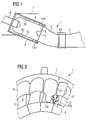
- Figure 1 is a section of a section a gas turbine with a combustion chamber arrangement according to the invention 1 shown.
- the combustion chamber arrangement 1 settles together from a large number of individual combustion chambers 3, which are arranged like a wreath and in a common annular gap 13 flow out.
- the annular gap 13 in turn opens into a turbine chamber 2, in which there are schematically indicated guide vanes and blades of the turbine.
- Burners 6 are connected upstream of the individual combustion chambers 3. These serve to ignite a mixture of an oxygen-containing Fuel gas and a fuel, which in the Single combustion chambers 3 continue to burn.
- the single combustion chambers 3 consist of one adjoining the burner 6 Input section 4 and an input section 4 in the direction of the annular gap 13 transition section 5 together.
- the burners 6 are with the individual combustion chambers 3 connected through an outer turbine housing 7. Starting from the turbine outer casing 7 in the direction of Turbine space 2, a nozzle 8 can be recognized, which concentrically around the circular cylindrical input section 4 of the single combustion chamber 3 extends. Between the nozzle 8 and the input section 4 of the single combustion chamber 3, a gap 9 is left, which by one Cooling fluid can be flowed through.
- the individual combustion chamber 3 are distributed along the circumference Ribs 10 are formed, with which the individual combustion chamber 3 is supported on the nozzle 8.
- the ribs 10 are shown in FIG Embodiment molded onto the individual combustion chamber 3, however, they can also be molded onto the connector 8 and extend in the direction of the single combustion chamber 3.
- a recess 11 can be seen on the side of the nozzle 8, at which an adjacent nozzle of an adjacent Single combustion chamber connects.
- the individual combustion chambers 3 are to be transferred into a common annular gap 13 the individual combustion chambers at an angle to each other arranged.
- the distance between the individual combustion chambers starting from the burner 6 in the direction of Annular gap 13 reduced, so that the cylindrical neck 8 from a certain extent in the direction of the annular gap 13 collide.
- the recesses 11 arranged to further in the nozzle 8 To be able to extend the direction of the annular gap 13 inwards. Adjacent ones lie along the edge of the recesses 11 Stub 8 to each other and can be used to seal each other connected, for example welded.
- the nozzles 8 arranged according to the invention form with their Gap space 9 a flow channel for a cooling fluid.
- This in the cooling channel carries cooling fluid guided in a quasi closed manner due to the defined flow channel effectively one convective cooling of the individual combustion chambers 3 in the Nozzle 8 covered area.
- FIGs 2 and 3 are perspective from different Viewing directions excerpts from trained according to the invention Combustion chamber arrangements shown.
- the individual combustion chamber 3 at least in the input section 4 surrounding nozzle 8 with the tongue-like extension 12a and 12b shown.
- Figure 2 is also with help arrows the course of the flow 14 of a coolant fluid from the openly cooled area towards the gap spaces below the tongue-like extensions 12a and shown below the nozzle 8.
- the tongue-like extensions 12a and 12b towards the exit leading into the gap space from the transition section 5 of the individual combustion chambers 3 rejuvenate. This creates a sufficiently large entrance area guaranteed for the cooling fluid flow.
Landscapes
- Engineering & Computer Science (AREA)
- Mechanical Engineering (AREA)
- General Engineering & Computer Science (AREA)
- Chemical & Material Sciences (AREA)
- Combustion & Propulsion (AREA)
- Turbine Rotor Nozzle Sealing (AREA)
Priority Applications (7)
| Application Number | Priority Date | Filing Date | Title |
|---|---|---|---|
| EP01121089A EP1288574A1 (fr) | 2001-09-03 | 2001-09-03 | Agencement de chambre de combustion |
| PCT/EP2002/009556 WO2003021149A1 (fr) | 2001-09-03 | 2002-08-27 | Dispositif a chambre de combustion |
| DE50207662T DE50207662D1 (de) | 2001-09-03 | 2002-08-27 | Brennkammeranordnung |
| JP2003525188A JP2005502020A (ja) | 2001-09-03 | 2002-08-27 | 燃焼器装置 |
| CNA028150961A CN1537212A (zh) | 2001-09-03 | 2002-08-27 | 燃烧室装置 |
| US10/488,622 US6968672B2 (en) | 2001-09-03 | 2002-08-27 | Collar for a combustion chamber of a gas turbine engine |
| EP02767441A EP1423647B1 (fr) | 2001-09-03 | 2002-08-27 | Dispositif a chambre de combustion |
Applications Claiming Priority (1)
| Application Number | Priority Date | Filing Date | Title |
|---|---|---|---|
| EP01121089A EP1288574A1 (fr) | 2001-09-03 | 2001-09-03 | Agencement de chambre de combustion |
Publications (1)
| Publication Number | Publication Date |
|---|---|
| EP1288574A1 true EP1288574A1 (fr) | 2003-03-05 |
Family
ID=8178516
Family Applications (2)
| Application Number | Title | Priority Date | Filing Date |
|---|---|---|---|
| EP01121089A Withdrawn EP1288574A1 (fr) | 2001-09-03 | 2001-09-03 | Agencement de chambre de combustion |
| EP02767441A Expired - Lifetime EP1423647B1 (fr) | 2001-09-03 | 2002-08-27 | Dispositif a chambre de combustion |
Family Applications After (1)
| Application Number | Title | Priority Date | Filing Date |
|---|---|---|---|
| EP02767441A Expired - Lifetime EP1423647B1 (fr) | 2001-09-03 | 2002-08-27 | Dispositif a chambre de combustion |
Country Status (6)
| Country | Link |
|---|---|
| US (1) | US6968672B2 (fr) |
| EP (2) | EP1288574A1 (fr) |
| JP (1) | JP2005502020A (fr) |
| CN (1) | CN1537212A (fr) |
| DE (1) | DE50207662D1 (fr) |
| WO (1) | WO2003021149A1 (fr) |
Families Citing this family (7)
| Publication number | Priority date | Publication date | Assignee | Title |
|---|---|---|---|---|
| US7155800B2 (en) | 2005-02-24 | 2007-01-02 | General Electric Company | Automated seal strip assembly method and apparatus for rotary machines |
| US7082766B1 (en) * | 2005-03-02 | 2006-08-01 | General Electric Company | One-piece can combustor |
| EP2211023A1 (fr) | 2009-01-21 | 2010-07-28 | Siemens Aktiengesellschaft | Distributeur pour turbomachine avec structure support d'aubes directrices segmentée |
| US8201412B2 (en) * | 2010-09-13 | 2012-06-19 | General Electric Company | Apparatus and method for cooling a combustor |
| DE102011007562A1 (de) * | 2011-04-18 | 2012-10-18 | Man Diesel & Turbo Se | Brennkammergehäuse und damit ausgerüstete Gasturbine |
| US8650852B2 (en) * | 2011-07-05 | 2014-02-18 | General Electric Company | Support assembly for transition duct in turbine system |
| CN117090688B (zh) * | 2023-08-29 | 2025-09-09 | 清航空天(北京)科技有限公司 | 一种浮动式爆震涡轮发动机 |
Citations (4)
| Publication number | Priority date | Publication date | Assignee | Title |
|---|---|---|---|---|
| US4719748A (en) * | 1985-05-14 | 1988-01-19 | General Electric Company | Impingement cooled transition duct |
| US4794753A (en) * | 1987-01-06 | 1989-01-03 | General Electric Company | Pressurized air support for catalytic reactor |
| US5323600A (en) * | 1993-08-03 | 1994-06-28 | General Electric Company | Liner stop assembly for a combustor |
| US6216442B1 (en) * | 1999-10-05 | 2001-04-17 | General Electric Co. | Supports for connecting a flow sleeve and a liner in a gas turbine combustor |
Family Cites Families (15)
| Publication number | Priority date | Publication date | Assignee | Title |
|---|---|---|---|---|
| US3169367A (en) * | 1963-07-18 | 1965-02-16 | Westinghouse Electric Corp | Combustion apparatus |
| US3840332A (en) * | 1973-03-05 | 1974-10-08 | Stone Platt Crawley Ltd | Combustion chambers |
| GB1492049A (en) * | 1974-12-07 | 1977-11-16 | Rolls Royce | Combustion equipment for gas turbine engines |
| US4008568A (en) * | 1976-03-01 | 1977-02-22 | General Motors Corporation | Combustor support |
| US4297842A (en) * | 1980-01-21 | 1981-11-03 | General Electric Company | NOx suppressant stationary gas turbine combustor |
| JPS59229114A (ja) * | 1983-06-08 | 1984-12-22 | Hitachi Ltd | ガスタ−ビン用燃焼器 |
| GB9220937D0 (en) * | 1992-10-06 | 1992-11-18 | Rolls Royce Plc | Gas turbine engine combustor |
| FR2710968B1 (fr) * | 1993-10-06 | 1995-11-03 | Snecma | Chambre de combustion à double paroi. |
| US6182451B1 (en) * | 1994-09-14 | 2001-02-06 | Alliedsignal Inc. | Gas turbine combustor waving ceramic combustor cans and an annular metallic combustor |
| US5737913A (en) * | 1996-10-18 | 1998-04-14 | The United States Of America As Represented By The Secretary Of The Air Force | Self-aligning quick release engine case assembly |
| JP3110338B2 (ja) * | 1997-02-12 | 2000-11-20 | 東北電力株式会社 | 燃焼器の蒸気による冷却構造 |
| GB2328011A (en) * | 1997-08-05 | 1999-02-10 | Europ Gas Turbines Ltd | Combustor for gas or liquid fuelled turbine |
| DE19801626B4 (de) * | 1998-01-17 | 2010-08-12 | Robert Bosch Gmbh | Diagnose eines NOx-Speicherkatalysators beim Betrieb von Verbrennungsmotoren |
| US6098397A (en) * | 1998-06-08 | 2000-08-08 | Caterpillar Inc. | Combustor for a low-emissions gas turbine engine |
| US6354071B2 (en) * | 1998-09-25 | 2002-03-12 | General Electric Company | Measurement method for detecting and quantifying combustor dynamic pressures |
-
2001
- 2001-09-03 EP EP01121089A patent/EP1288574A1/fr not_active Withdrawn
-
2002
- 2002-08-27 EP EP02767441A patent/EP1423647B1/fr not_active Expired - Lifetime
- 2002-08-27 US US10/488,622 patent/US6968672B2/en not_active Expired - Fee Related
- 2002-08-27 JP JP2003525188A patent/JP2005502020A/ja not_active Abandoned
- 2002-08-27 DE DE50207662T patent/DE50207662D1/de not_active Expired - Fee Related
- 2002-08-27 WO PCT/EP2002/009556 patent/WO2003021149A1/fr not_active Ceased
- 2002-08-27 CN CNA028150961A patent/CN1537212A/zh active Pending
Patent Citations (4)
| Publication number | Priority date | Publication date | Assignee | Title |
|---|---|---|---|---|
| US4719748A (en) * | 1985-05-14 | 1988-01-19 | General Electric Company | Impingement cooled transition duct |
| US4794753A (en) * | 1987-01-06 | 1989-01-03 | General Electric Company | Pressurized air support for catalytic reactor |
| US5323600A (en) * | 1993-08-03 | 1994-06-28 | General Electric Company | Liner stop assembly for a combustor |
| US6216442B1 (en) * | 1999-10-05 | 2001-04-17 | General Electric Co. | Supports for connecting a flow sleeve and a liner in a gas turbine combustor |
Also Published As
| Publication number | Publication date |
|---|---|
| EP1423647A1 (fr) | 2004-06-02 |
| EP1423647B1 (fr) | 2006-07-26 |
| WO2003021149A1 (fr) | 2003-03-13 |
| JP2005502020A (ja) | 2005-01-20 |
| US20040237500A1 (en) | 2004-12-02 |
| DE50207662D1 (de) | 2006-09-07 |
| CN1537212A (zh) | 2004-10-13 |
| US6968672B2 (en) | 2005-11-29 |
Similar Documents
| Publication | Publication Date | Title |
|---|---|---|
| DE69412484T2 (de) | Verbrennungskammer eines gasturbinenmotors | |
| DE69509791T2 (de) | Brennkammerwandstruktur | |
| EP2179143B1 (fr) | Refroidissement de fente entre une paroi de chambre de combustion et une paroi de turbine d'une installation de turbine à gaz | |
| EP3239612B1 (fr) | Chambre de combustion de turbine à gaz | |
| DE112013007579B4 (de) | Flüssigbrennstoffpatrone für eine Brennstoffdüse und Brennstoffdüse | |
| EP2927594B1 (fr) | Chambre de combustion d'une turbine à gaz | |
| DE102011000879A1 (de) | Angewinkelte Leitschaufeln in eriner Brennkammerströmungshülse | |
| CH698347A2 (de) | Brennstoffdüse mit integriertem Einlassströmungskonditionierer. | |
| DE3821078A1 (de) | Ringvergasungsbrenner fuer gasturbine | |
| DE102011055109A1 (de) | Anlage zum Lenken des Luftstroms in einer Kraftstoffdüsenanordnung | |
| EP2808611A1 (fr) | Injecteur pour l'introduction d'un mélange air-carburant dans une chambre de combustion | |
| WO2012113553A1 (fr) | Chambre de combustion de turbine à gaz | |
| WO2010105956A1 (fr) | Dispositif de brûleur pour combustibles fluides et procédé de fabrication du dispositif de brûleur | |
| DE3871951T2 (de) | Brennstoffeinspritzvorrichtung fuer turbinenmotoren. | |
| EP3245451B1 (fr) | Chambre de combustion pour turbine à gaz, délimitée par une paroi | |
| DE112017001602B4 (de) | Brennkammer und gasturbine | |
| DE69502984T2 (de) | Gasturbinenbrennkammer | |
| EP1423647B1 (fr) | Dispositif a chambre de combustion | |
| DE1179767B (de) | Brennkammer | |
| EP3321589B1 (fr) | Buse de carburant d'une turbine à gaz dotée du générateur de tourbillons | |
| DE102016212649A1 (de) | Brennerdichtung einer Gasturbine und Verfahren zu deren Herstellung | |
| EP3004741B1 (fr) | Chambre de combustion tubulaire dotée d'une zone d'extrémité et turbine à gaz | |
| DE102012002465A1 (de) | Gasturbinenbrennkammer mit unsymmetrischen Kraftstoffdüsen | |
| EP1284391A1 (fr) | Chambre de combustion pour turbines à gaz | |
| DE1601532B2 (de) | Flammrohr fuer eine gasturbinenbrennkammer |
Legal Events
| Date | Code | Title | Description |
|---|---|---|---|
| PUAI | Public reference made under article 153(3) epc to a published international application that has entered the european phase |
Free format text: ORIGINAL CODE: 0009012 |
|
| AK | Designated contracting states |
Kind code of ref document: A1 Designated state(s): AT BE CH CY DE DK ES FI FR GB GR IE IT LI LU MC NL PT SE TR Designated state(s): AT BE CH CY DE DK ES FI FR GB GR IE IT LI LU MC NL PT SE TR |
|
| AX | Request for extension of the european patent |
Extension state: AL LT LV MK RO SI |
|
| AKX | Designation fees paid | ||
| REG | Reference to a national code |
Ref country code: DE Ref legal event code: 8566 |
|
| STAA | Information on the status of an ep patent application or granted ep patent |
Free format text: STATUS: THE APPLICATION IS DEEMED TO BE WITHDRAWN |
|
| 18D | Application deemed to be withdrawn |
Effective date: 20030906 |