EP1288742A2 - Unité de traitement et appareil électrophotographique - Google Patents
Unité de traitement et appareil électrophotographique Download PDFInfo
- Publication number
- EP1288742A2 EP1288742A2 EP02019502A EP02019502A EP1288742A2 EP 1288742 A2 EP1288742 A2 EP 1288742A2 EP 02019502 A EP02019502 A EP 02019502A EP 02019502 A EP02019502 A EP 02019502A EP 1288742 A2 EP1288742 A2 EP 1288742A2
- Authority
- EP
- European Patent Office
- Prior art keywords
- photosensitive member
- electrophotographic photosensitive
- intermediate transfer
- transfer belt
- process cartridge
- Prior art date
- Legal status (The legal status is an assumption and is not a legal conclusion. Google has not performed a legal analysis and makes no representation as to the accuracy of the status listed.)
- Withdrawn
Links
Images


Classifications
-
- G—PHYSICS
- G03—PHOTOGRAPHY; CINEMATOGRAPHY; ANALOGOUS TECHNIQUES USING WAVES OTHER THAN OPTICAL WAVES; ELECTROGRAPHY; HOLOGRAPHY
- G03G—ELECTROGRAPHY; ELECTROPHOTOGRAPHY; MAGNETOGRAPHY
- G03G21/00—Arrangements not provided for by groups G03G13/00 - G03G19/00, e.g. cleaning, elimination of residual charge
- G03G21/16—Mechanical means for facilitating the maintenance of the apparatus, e.g. modular arrangements
- G03G21/18—Mechanical means for facilitating the maintenance of the apparatus, e.g. modular arrangements using a processing cartridge, whereby the process cartridge comprises at least two image processing means in a single unit
- G03G21/1803—Arrangements or disposition of the complete process cartridge or parts thereof
- G03G21/181—Manufacturing or assembling, recycling, reuse, transportation, packaging or storage
-
- G—PHYSICS
- G03—PHOTOGRAPHY; CINEMATOGRAPHY; ANALOGOUS TECHNIQUES USING WAVES OTHER THAN OPTICAL WAVES; ELECTROGRAPHY; HOLOGRAPHY
- G03G—ELECTROGRAPHY; ELECTROPHOTOGRAPHY; MAGNETOGRAPHY
- G03G15/00—Apparatus for electrographic processes using a charge pattern
- G03G15/14—Apparatus for electrographic processes using a charge pattern for transferring a pattern to a second base
- G03G15/16—Apparatus for electrographic processes using a charge pattern for transferring a pattern to a second base of a toner pattern, e.g. a powder pattern, e.g. magnetic transfer
- G03G15/1605—Apparatus for electrographic processes using a charge pattern for transferring a pattern to a second base of a toner pattern, e.g. a powder pattern, e.g. magnetic transfer using at least one intermediate support
-
- G—PHYSICS
- G03—PHOTOGRAPHY; CINEMATOGRAPHY; ANALOGOUS TECHNIQUES USING WAVES OTHER THAN OPTICAL WAVES; ELECTROGRAPHY; HOLOGRAPHY
- G03G—ELECTROGRAPHY; ELECTROPHOTOGRAPHY; MAGNETOGRAPHY
- G03G21/00—Arrangements not provided for by groups G03G13/00 - G03G19/00, e.g. cleaning, elimination of residual charge
- G03G21/16—Mechanical means for facilitating the maintenance of the apparatus, e.g. modular arrangements
- G03G21/18—Mechanical means for facilitating the maintenance of the apparatus, e.g. modular arrangements using a processing cartridge, whereby the process cartridge comprises at least two image processing means in a single unit
- G03G21/1803—Arrangements or disposition of the complete process cartridge or parts thereof
- G03G21/1817—Arrangements or disposition of the complete process cartridge or parts thereof having a submodular arrangement
- G03G21/1821—Arrangements or disposition of the complete process cartridge or parts thereof having a submodular arrangement means for connecting the different parts of the process cartridge, e.g. attachment, positioning of parts with each other, pressure/distance regulation
-
- G—PHYSICS
- G03—PHOTOGRAPHY; CINEMATOGRAPHY; ANALOGOUS TECHNIQUES USING WAVES OTHER THAN OPTICAL WAVES; ELECTROGRAPHY; HOLOGRAPHY
- G03G—ELECTROGRAPHY; ELECTROPHOTOGRAPHY; MAGNETOGRAPHY
- G03G2215/00—Apparatus for electrophotographic processes
- G03G2215/01—Apparatus for electrophotographic processes for producing multicoloured copies
- G03G2215/0167—Apparatus for electrophotographic processes for producing multicoloured copies single electrographic recording member
- G03G2215/0174—Apparatus for electrophotographic processes for producing multicoloured copies single electrographic recording member plural rotations of recording member to produce multicoloured copy
- G03G2215/0177—Rotating set of developing units
-
- G—PHYSICS
- G03—PHOTOGRAPHY; CINEMATOGRAPHY; ANALOGOUS TECHNIQUES USING WAVES OTHER THAN OPTICAL WAVES; ELECTROGRAPHY; HOLOGRAPHY
- G03G—ELECTROGRAPHY; ELECTROPHOTOGRAPHY; MAGNETOGRAPHY
- G03G2221/00—Processes not provided for by group G03G2215/00, e.g. cleaning or residual charge elimination
- G03G2221/16—Mechanical means for facilitating the maintenance of the apparatus, e.g. modular arrangements and complete machine concepts
- G03G2221/1642—Mechanical means for facilitating the maintenance of the apparatus, e.g. modular arrangements and complete machine concepts for the transfer unit
Definitions
- the present invention relates to a process cartridge and an electrophotographic apparatus, and in particular to an intermediate transfer belt-electrophotographic photosensitive member integrated process cartridge and an electrophotographic apparatus having the process cartridge.
- An image forming apparatus of electrophotographic system (electrophotographic apparatus) using a belt-shaped intermediate transferring member (intermediate transfer belt) is effective as color electrophotographic apparatus and multi-color image forming apparatus which brings a plurality of component color images of color image information or multi-color image information into sequential lamination transfer so as to output an image formed matter synthesized and reproduced from color images and multi-color images.
- a color electrophotographic apparatus using an intermediate transfer belt does not require any processing or control (for example, prehension to a gripper or absorbing, giving curvature, etc.) on the transfer material but can transfer images from the intermediate transfer belt, and therefore has an advantage that various kinds of transfer material can be selected regardless of wideness/narrowness of width or longness/shortness of length to cover thin paper (40 g/m 2 paper) to thick paper (200 g/m 2 paper) such as envelops, postcards, and label forms, etc.
- intermediate transfer member intermediate transfer drum
- intermediate transfer belt shape for the intermediate transfer member
- inorganic materials such as zinc oxide, selenium and cadmium sulfide, etc. are known.
- organic materials such as polyvinyl carbazole, phthalocyanine, and azo pigment have advantages such as high production efficiency or pollution-free performance, and in particular are superior in photoconductivity.
- Organic electrophotographic photosensitive members using such organic materials are widely used for electrophotographic apparatuses.
- An intermediate transfer belt repeatedly receives bending stress and contact with or rubbing from various kinds of drive members and transfer members etc. every time it rotates, and with high potential being applied, its life is shorter than the main body of an electrophotographic apparatus, and replacement is indispensable under the current state.
- electrophotographic photosensitive member is also repeatedly affected by electrification, exposure, development, transfer, cleaning, dielectrification, and therefore requires various chemical or physical endurance, thus an organic electrophotographic photosensitive member needs to be replaced as well.
- waste toner having collected residual toner on an intermediate transfer belt needs treatment, and a lot of components such as an electrophotographic photosensitive member, developing means and toner, etc. need replacement and maintenance.
- Japanese Patent Application Laid-Open No. 8-137181 proposes to dispose an intermediate transfer belt and an electrophotographic photosensitive member as respectively independent units detachably mountable to the main body of an electrophotographic apparatus without difficulty.
- replacing means to cause the intermediate transfer belt and the electrophotographic photosensitive member (replacement parts) to be supported integrally as one body in one unit, and to be constructed so as to cause to be simultaneously removed from/attached to the main body of the electrophotographic apparatus are suitable, and are proposed in Japanese Patent Application Laid-Open No. 6-110261, Japanese Patent Application Laid-Open No. 10-177329, and Japanese Patent Application Laid-Open No. 11-30944.
- the method to construct the intermediate transfer belt and the electrophotographic photosensitive member as one-body unit to become an intermediate transfer belt-electrophotographic photosensitive member integrated process cartridge that is detachably mountable to the main body of the electrophotographic apparatus gives rise to several problems originated from the intermediate transfer belt.
- the electrophotographic photosensitive member as well as the intermediate transfer belt contain various materials being mixed in order to obtain required functions, and among those materials some may affect adversely each other by being left for a long time.
- an organic electrophotographic photosensitive member is apt to be influenced thereby.
- difference in sensitivity characteristic is brought about in that portion, giving rise to density difference from the neighborhood at the time of printing to provide an abnormal image.
- the intermediate transfer belt partly changes in electric characteristics such as resistance or capacity will result in transfer unevenness which will appear in the image.
- the object of the present invention is to solve the above described problems and to provide a process cartridge that makes maintenance easy, can attain miniaturization as well as cost reduction of the electrophotographic apparatus which is attached/removed, and can provide good images, and an electrophotographic apparatus having the process cartridge.
- the present invention provides a process cartridge which is detachably mountable to a main body of an electrophotographic apparatus, integrally comprising:
- an electrophotographic apparatus comprising:
- the initial goal has been attained by adopting several constructions together for a process cartridge in which an intermediate transfer belt and an organic electrophotographic photosensitive member are integrated, and also primary transfer means for primarily transferring a toner image on the electrophotographic photosensitive member to the intermediate transfer belt is further integrated.
- the present invention has the features that after the electrophotographic photosensitive member and the intermediate transfer belt are brought into contact with each other under a linear pressure of 0.5 N/cm to form a contact part, and are left to stand for 10 hours in an environment of 45°C/95%RH, differences in the dark portion potential and the light portion potential of the electrophotographic photosensitive member between the contact part and the part not in contact with the intermediate transfer belt (non-contact part) are respectively less than 20%, and no crack having a length of not less than 1 ⁇ m occurs in any of the surface of the electrophotographic photosensitive member and the surface of the intermediate transfer belt.
- the materials that may migrate or move when the intermediate transfer belt and the electrophotographic photosensitive member are brought into contact need to be made less, or made into a form not apt to be moved, and there are several methods.
- an inert particle additive is mixed into or attached to the intermediate transfer belt and/or the electrophotographic photosensitive member to provide extremely micro protrusions on their surfaces so that the contact area therebetween is reduced and movement of matters is prevented
- a method in which the binder resin of the intermediate transfer belt and/or the electrophotographic photosensitive member is made into a form having a higher molecular weight or cross-linked so that movement of matters of low molecule weight is prevented and the like is a method in which an inert particle additive is mixed into or attached to the intermediate transfer belt and/or the electrophotographic photosensitive member to provide extremely micro protrusions on their surfaces so that the contact area therebetween is reduced and movement of matters is prevented
- the layer containing charge transporting material that the electrophotographic photosensitive member used for the process cartridge of the present invention may preferably have a thickness of 10 to 60 ⁇ m, more preferably 15 to 40 ⁇ m.
- the charge transporting material may preferably be in a content of 20 to 80 % by weight, more preferably 30 to 60 % by weight based on the total weight of the layer that contains charge transporting material.
- the sensitivity may lower.
- the film thickness is preferably controlled to be not less than 10 ⁇ m while the charge transporting material is preferably controlled to be not more than 80 % by weight.
- the layer containing charge transporting material refers to, in the case where the photosensitive layer the electrophotographic photosensitive member has is a single layer type photosensitive layer containing the charge generation material and the charge transporting material in a single layer, that single layer type photosensitive layer, and, in the case where the photosensitive layer is a lamination type photosensitive layer which has a charge generation layer containing charge generation material and a charge transport layer containing charge transporting material in a laminated form, to the charge transport layer.
- the layer construction of the photosensitive layer is preferably a lamination type photosensitive layer in which a charge generation layer and a charge transport layer are laminated in this order from the bottom.
- binder resin to be utilized for the electrophotographic photosensitive member using organic photoconductive material polyester, polyurethane, polyarylate, polyethylene, polystyrene, polybutadiene, polycarbonate, polyamide, polypropylene, polyimide, polyamideimide, polysulfone, polyaryl ether, polyacetal, phenolic resin, acrylic resin, silicone resin, epoxy resin, urea resin, allylic resin, alkyd resin, butyral resin, the like can be mentioned.
- the charge transport layer contains polycarbonate or polyarylate as binder resin, from the point of view that such a phenomena that the additive existing in the electrophotographic photosensitive member such as the charge transporting material in the present invention is shifted to the intermediate transfer belt is made to hardly take place.
- phthalocyanine pigment for example, phthalocyanine pigment, polycyclic pigment, azo pigment, perylene pigment, indigo pigment, quinacridone pigment, azurenium salt dye, squa-rylium dye, cyanine dye, pyrylium dye, thiopyrylium dye, xanthene pigment, quinoneimine pigment, triphenylmethane pigment, styryl pigment, selenium, selenium-tellurium, amorphous silicon, cadmium sulfide, and the like can be mentioned.
- charge transporting material pyrene compounds, carbazole compounds, hydrazone compounds, N,N-dialkylaniline compound, diphenylamine compound, triphenylamine compound, triphenylmethane compounds, pyrazoline compounds, styryl compounds, stilbene comprounds, and the like can be mentioned, but the charge transporting material having structure represented by the following formula(1) or the charge transporting material having structure represented by the following formula(2) is preferable from the point of view that those materials do not tend to move even when they are in contact with the intermediate transfer belt for a long period at high temperature and high humidity and no streak-like image defect due to the attachment of those materials to the intermediate transfer belt is formed and that electrifying deterioration is less and residual potential can be reduced with high sensitivity and the like.
- the charge transporting material having structure represented by the above described formula
- a protecting layer may be formed for the purpose of protecting the photosensitive layer.
- Film thickness of the protecting layer is preferably 0.01 to 20 ⁇ m and moreover preferably 0.1 to 10 ⁇ m.
- the protecting layer may contain the above described charge generation material or charge transporting material, metal as well as oxide thereof, nitrides, salts, alloy and moreover conductive material such as carbon.
- reactive epoxy, (meta) acrylic monomer or oligomer can be used after subject to mixture and hardening.
- the supporting member used for the electrophotographic photosensitive member metals such as iron, copper, nickel, aluminum, titanium, tin, antimony, indium, lead, zinc, gold and silver, alloy thereof, or oxides thereof or carbon, conductive resins and the like can be used.
- the shape of the supporting member includes cylinder type, belt type and sheet type.
- the above described conductive material may be molded and processed, but may be coated as a paint or may be evaporated and deposited.
- An intermediate layer may be provided between the supporting member and the photosensitive layer.
- the intermediate layer which mainly consists of binder resin, may contain the above described conductive material or acceptor.
- polyester, polyurethane, polyarylate, polyethylene, polystyrene, polybutadiene, polycarbonate, polyamide, polypropylene, polyimide, polyamideimide, polysulfone, polyaryl ether, polyacetal, phenolic resin, acrylic resin, silicon resin, epoxy resin, urea resin, allylic resin, alkyd resin, butyral resin, and the like can be mentioned.
- the method such as vapor deposition or coating is adopted.
- coating bar coater, knife coater, roller coater, attriter, spray, dip coating, electrostatic coating, powder coating, or the like are used.
- the process cartridge of the present invention is preferably arranged to have charge providing means to give electric charges in polarity opposite to the polarity of the toner at the time of the primary transfer to the toner on the intermediate transfer belt to return the toner on the intermediate transfer belt to the electrophotographic photosensitive member at the contact part between the intermediate transfer belt and the electrophotographic photosensitive member to clean the intermediate transfer belt.
- a blade charger and a corona charger can be used.
- the toner thus returned to the electrophotographic photosensitive member from the intermediate transfer belt is removed with electrophotographic photosensitive member cleaning means such as a cleaning blade.
- This intermediate transfer belt cleaning system gives rise to a significant effect in miniaturization and cost reduction of process cartridge compared with a system with cleaning blades, etc. being provided in the electrophotographic photosensitive member and the intermediate transfer belt respectively and with feeding mechanism and a container for waste toner being provided.
- the shape of the electrophotographic photosensitive member incorporated in the process cartridge is also important. From that view point, the electrophotographic photosensitive member is preferably shaped as a drum that has simple drive mechanism and can be easily miniaturized, and the diameter is preferably not more than 60 mm.
- enhancement in reduction of diameter of the electrophotographic photosensitive member can reduce the area of the contact part between the intermediate transfer belt and the electrophotographic photosensitive member, or the portion where no contact does not occur but approaching with extremely close distance takes place, thereby gives rise to an effect to minimize the region where a problem occurs during long period storage.
- the method in which the intermediate transfer belt is placed over two rollers can enhance reduction in the number of components and miniaturization can be accelerated.
- the roller for applying tension onto the intermediate transfer belt may preferably slide at least 1 mm or more in the elongating direction of the intermediate transfer belt in order to correspond with elongation of the intermediate transfer belt, and in order that the intermediate transfer belt is certainly driven without slipping, the intermediate transfer belt is preferably placed over the rollers with force of 5 N or more.
- the range of volume resistivity of the intermediate transfer belt is preferably 1 ⁇ 10 6 to 8 ⁇ 10 13 ⁇ cm.
- the volume resistivity being less than 1 ⁇ 10 6 ⁇ cm, the resistance is too low to give sufficient transfer electric field and may give rise to lack of images and rough images.
- the volume resistivity being higher than 8 ⁇ 10 13 ⁇ cm, the transfer voltage needs to be set high, and the power supply may be enlarged or cost increase may be introduced.
- the wall thickness of the intermediate transfer belt is preferably 40 to 300 ⁇ m. With less than 40 ⁇ m, the intermediate transfer belt may lack in form stability to tend to give rise to unevenness in thickness, and its enduring intensity is insufficient, and breaking or a crack may occur. On the other hand, with more than 300 ⁇ m, the quantity of materials used increases, making costs higher, and moreover, the peripheral speed balance between the interior face and the exterior face of the intermediate transfer belt in the roller portion over which the intermediate transfer belt is placed, thus such a problem as image scattering due to elongation/contraction of the exterior face is apt to occur. Also, such a problem that the intermediate transfer belt may exhibit a decreased bending endurance and become more rigid so that the driving torque may increase and the main body of the electrophotographic apparatus may be enlarged or cost increase may be introduced is brought about.
- the process cartridge of the present invention is set to be the process cartridge integrally supporting the intermediate transfer belt and the electrophotographic photosensitive member in one body, but it goes well if they are in one body at the time when a user use them, and considering handling them during the production process and simplicity in dismantling thereof after collection, for example, a designing that enables separation into several units such as the intermediate transfer belt unit and the electrophotographic photosensitive member unit is preferably adopted.
- the method of forming the intermediate, transfer belt may be a method of producing seamless belts.
- As the producing method a method that features high manufacturing efficiency and can control costs is preferable.
- such a method such a method that executes continuous melt extrusion from a circular die and thereafter cuts the extruded product into a form with a necessary length to produce a belt can be mentioned.
- inflation molding is suitable.
- FIG. 3 An apparatus for forming the intermediate transfer belts of the present invention is schematically shown in FIG. 3.
- the present apparatus basically comprises an extruder, an extruder die and a gas blowing unit.
- an extrusion resin, a conducting agent, and additives etc. are preliminarily mixed in advance in accordance with a desired formulation and thereafter kneaded and dispersed to prepare an extrusion material, which is then put into a hopper 102 provided to an extruder 100.
- the extruder 100 has a preset temperature and extruder screw construction which are selected so that the extrusion material may have a melt viscosity necessary for enabling the extrusion into a belt in the subsequent steps and also the materials can uniformly be dispersed each other.
- the extrusion material is melt-kneaded in the extruder 100 into a melt, which then enters the cylinder-type extruder die 103.
- a gas inlet passage 104 is disposed, and air is blown into the center of the cylinder-type die 103 from the gas inlet passage 104 so that the melted body having passed through the die 103 inflates while scaling up in the radius direction to be a cylinder film 110.
- a method is adapted in which the product in the tubular form is crushed from the left and the right with the stabilizing plate 106 and folded into a sheet and it is then sandwiched by a pinch roller 107 without the internal air coming out so that it is drawn at a constant speed.
- the drawn film is cut with a cutting apparatus 108 so as to provide a cylindrical film in a desired size.
- heat processing involving molds is preferably implemented for various purposes of removing the migrating matters, adjusting the surface flatness, improving the size accuracy, removing crease left in the film at the time of forming, and the like.
- the coefficient of thermal expansion of the cylinder mold with small diameter is set to get larger than the coefficient of thermal expansion of the cylinder mold with large diameter (external mold), and after this internal mold is covered with a molded tubular film, that internal mold is inserted into the external mold in such a fashion that the internal mold and the external mold sandwich the tubular film.
- the gap between the molds is given subject to calculation from the heating temperature, difference in the coefficient of thermal expansion between the internal mold, and the external mold and the pressure regarded as necessary.
- the molds set in order of the internal mold, the tubular film, and the external mold are heated to reach near softening point temperature of the resin.
- the internal mold with larger coefficient of thermal expansion is heated to expand larger than the external mold and a uniform pressure is applied to all over the tubular film.
- the temperature at this time is adjusted to reach around the softening point of the resin.
- the surface of the resin film is pushed onto the inner face of the external mold subjected to toughness adjustment, the surface toughness of the surface of the resin film is adjusted to reach an optimal value, and at the same time, the matter becoming a cause to give rise to cracks in the electrophotographic photosensitive member is evaporated or attached to the mold so as to be removed from inside the film.
- the film is cooled and taken away from the mold to obtain a belt in which size and surface properties are controlled.
- reinforcement members and guide members or position detecting members are attached as the need arises and accurate cutting is implemented so as to produce the intermediate transfer belt.
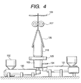
- the above described description relates to a single layer belt, and in case of a belt of two-layer structure, as shown in Fig. 4, another extruder 101 is additionally disposed, simultaneously with the kneaded and melted product from the extruder 100, the kneaded and melted product from the extruder 110 is sent to the circular die 103 for two layers so that the two layers are simultaneously enlarged and expanded to obtain a two-layer belt.
- intermediate transfer belts of not only of a single layer but also multi-layer construction can be formed in one step, and in short time and with good size accuracy. Possibility of this short-time forming means possibility of weight production and low-cost production.
- the thickness ratio of the circular die and the tubular film formed is the ratio between the width of the gap of the circular die (die slit) and the thickness of the tubular film formed, and the latter is preferably one third or less of the former, and more preferably one fifth or less.
- the ratio of the diameter of the circular die and the tubular film formed is to express by percentage the ratio of the outer diameter of the tubular film 110 to the outer diameter of the die slit of the circular die 103, and preferably falls within the range of 101% to 300%.
- a resin being a main material which is not limited in particular if it fulfills features of the present invention
- olefin resin such as polyethylene and polypropylene, polystyrene resin, acrylic resin, polyester resin, polycarbonate, sulfur-containing resins such as polysulfone and polyether sulfone as well as polyphenylene sulfide, etc.
- fluorine resins such as polyvinylidene fluoride and polyethylene-tetrafluoroethylene copolymer, etc., polyurethane resin, silicon resin, ketone resin, polyvinylinde chloride, thermoplastic polyimide resin, polyamide resin, modified polyphenylene oxide resin and the like, various modified resins and copolymers of these can be used alone or in combination of two or more kinds of the resins.
- the present invention will not be limited to the above described materials.
- additives for mixture to adjust electric resistance value of the intermediate transfer belt to be used in the process cartridge of the present invention will not be limited in particular, and as conductive filler to adjust resistance, carbon black and various kinds of conductive metal oxides, etc. are used and as non-filler system resistance adjusting agent, an antistatic resin containing an ether bond or a hydroxyl group, etc. in the molecule or organic high-molecular compounds showing electronic conduction are used.
- Ion conducting agents with low molecular weight such as various kinds of metallic salts and glycols are apt to migrate or move to the electrophotographic photosensitive member, and are not preferable in general, but not all of the materials will cause problems and the materials can use within such a range that the features of the present invention are obtainable.
- FIG. 1 An example of an electrophotographic apparatus using an intermediate transfer belt-electrophotographic photosensitive member integrated process cartridge of the present invention is shown in Fig. 1.
- Fig. 1 shows a full-color electrophotographic apparatus (a photocopier or a laser beam printer).
- Reference numeral 1 denotes an electrophotographic photosensitive member of a rotating drum type repeatedly used as a first image bearing member, and is driven for rotation at a predetermined peripheral velocity (process speed) in the direction of an arrow.
- the electrophotographic photosensitive member 1 undergoes electrical charging treatment uniformly at a predetermined polarity and potential with the (primary) charging means 2 in the course of the rotation.
- the photosensitive member 1 receives light 3 from not-shown exposing means (color separation-image forming exposure optical system of a color image of original, scanning exposure system with a laser scanner outputting laser beams modulated in accordance with time-sequential electric digital pixel signal of image information, and the like), whereby an electrostatic latent image is formed corresponding to the first color component image (for example, yellow color component image) of the desired full color image.
- not-shown exposing means color separation-image forming exposure optical system of a color image of original, scanning exposure system with a laser scanner outputting laser beams modulated in accordance with time-sequential electric digital pixel signal of image information, and the like
- the electrostatic latent image is developed with a first-color, yellow toner Y, by use of a first developing means (yellow color developing means 41).
- a first developing means yellow color developing means 41
- the respective developing means of second to forth developing means magenta color developing means 42, cyan color developing means 43 and black color developing means 44
- magenta color developing means 42, cyan color developing means 43 and black color developing means 44 are operated off not. to act on the electrophotographic photosensitive member 1 and the first color, yellow toner image is not affected by the second to forth developing means.
- the intermediate transfer belt 5 is driven for rotation at the same peripheral speed as that of the photosensitive member 1 in the direction of an arrow.
- the above described first yellow toner image formed and carried on the electrophotographic photosensitive member 1 passes through the contact part between the electrophotographic photosensitive member 1 and the intermediate transfer belt 5, in the course of which it is successively primarily transferred to the external circumference face of the intermediate transfer belt 5 by the aid of an electric field formed by the primary transfer bias applied onto the intermediate transfer belt 5 from the primary transfer means 6.
- the surface of the electrophotographic photosensitive member 1 having completed transfer of the first color yellow toner image to the intermediate transfer belt 5 is cleaned with electrophotographic photosensitive member cleaning means 13.
- the third color cyanogens toner image and the forth color black toner image are sequentially transferred superimposingly onto the intermediate transfer belt 5, and a synthesized color toner image corresponding to the intended full color image is formed.
- Reference numeral 7 denotes a secondary transfer means (secondary transfer roller) that is borne in parallel with the secondary transfer roller 8 and is disposed in the bottom face of the intermediate transfer belt 5 in a state capable of being separable therefrom.
- secondary transfer roller secondary transfer roller
- the primary transfer bias for sequential superimposing transfer of the first to the forth toner images from the electrophotographic photosensitive member 1 to the intermediate transfer belt 5 is applied in a reverse polarity (+) to that of the toner from the bias power source 30.
- the voltage thus applied may be in the range of from +100V to 2kV, for example.
- the secondary transfer means 7 can be separated from the intermediate transfer belt 5.
- the secondary transfer means 7 are brought into contact with the intermediate transfer belt 5, and the transfer material P is fed to the contact part between the intermediate transfer belt 5 and the secondary transfer means 7 at a predetermined timing from a paper feeding roller 11 through a transfer material guide 10 and a secondary transfer bias is applied to the secondary transfer means 7 from the source 31.
- a synthesized color toner image is secondarily transferred from the intermediate transfer belt 5 to the transfer material P.
- the transfer material P having received the transfer of the toner images is then introduced into the fixing means 15 to undergo heat fixing.
- electric charge providing means (charge providing roller) 9 is brought into contact with the intermediate transfer belt 5, where the charge providing means is disposed freely in a separate/contact state relative to the charge providing means, and a bias with a reverse polarity to that of the electrophotographic photosensitive member 1 is applied so that electric charges with a reverse polarity to that at the time of the primary transfer are given to the toners not transferred to transfer material P and remaining on the intermediate transfer belt 5 (i.e., transfer residual toners).
- a voltage formed by superimposing a direct current voltage to alternate current voltage is applied to the bias power source 33 so that electric charges with a reverse polarity to that at the time of the primary transfer are given to the toners not transferred to transfer material P and remaining on the intermediate transfer belt 5 (i.e., transfer residual toners).
- the transfer residual toners charged in a reverse polarity to that at the time of the primary transfer are electrostatically transferred to the electrophotographic photosensitive member 1 at the contact part of the intermediate transfer member with the electrophotographic photosensitive member 1 as well as in the vicinity thereof so that the intermediate transfer member is cleaned. Since this step can be implemented simultaneously with the primary transfer, reduction in throughput does not occur.
- This intermediate transfer belt cleaning system will work only by addition of a charge providing member for giving electric charges to the transfer residual toner (electric charge providing means), and compared with the case where cleaning means and a waste toner box are separately installed on the intermediate transfer belt, miniaturization as well as cost reduction of the electrophotographic apparatus can be achieved.
- waste toner container since all of the waste toner gets together to the waste toner container that is attached to the electrophotographic photosensitive member, the waste toner container is also replaced when the process cartridge is replaced, and another waste toner box is not needed to be replaced, improving maintenance performance.
- this intermediate transfer belt cleaning system activates the present invention and is preferable.
- the process cartridge of the present invention shown in Fig. 2 is constructed as a one-body unit comprising an intermediate transfer belt 5, an electrophotographic photosensitive member 1, charge providing means 9, electrophotographic photosensitive member cleaning means 13, and roller-shape primary transfer means 6 to be housed in a not-shown frame and to be made easily detachably mountable to the main body of the electrophotographic apparatus.
- the process cartridge shown in Fig. 2 comprises a mechanism to charge the transfer residual toner in a reverse polarity to that of the primary transfer as mentioned above, and to return the toner to the electrophotographic photosensitive member in the primary transfer part, that is, in the present drawing, roller-shape charge providing means (electric charge providing roller) 9 made of elastic member with medium resistance.
- a not-shown waste toner container is also integrated, the transfer residual toner on the both of the intermediate transfer belt and the electrophotographic photosensitive member is discarded at the same time when the cartridge is replaced and contributes to improvement in maintenance performance.
- the intermediate transfer belt is placed over and around two rollers 8 and 12 so that reduction in number of components and miniaturization are achieved.
- a driving roller 8 serves at the same time as a facing roller to the electric charge providing roller as well as a secondary transfer facing roller.
- a tension roller 12 that rotates following the intermediate transfer belt has a sliding mechanism and is brought into press contact in the direction of an arrow with a compressing spring to give tension to the intermediate transfer belt.
- Slide width thereof is about 1 to 5 mm and the total pressure of the spring is around 5 to 100 N.
- the electrophotographic photosensitive member 1 and the driving roller 8 have a not-shown coupling so that the rotation drive force is transmitted from the main body.
- an intermediate transfer belt 5 is placed over and around a rubber roller 12 with a diameter of 30 mm which is prepared by winding rubber (the one which has already been confirmed to give no influence to the intermediate transfer belt) with a thickness of 5 mm and JIS hardness of 45° around an aluminum cylinder having a diameter of 20 mm.
- Reference numeral 50 denotes a roller facing the electrophotographic photosensitive member.
- Reference numeral 12 denotes a tension roller onto which a force of 20 N is applied in the direction of the arrow.
- the electrophotographic photosensitive member 1 is brought into contact with the intermediate transfer belt with a force of linear pressure of 0.5 N/cm ⁇ 5%.
- the contacting portion is marked in advance both in the intermediate transfer belt and the electrophotographic photosensitive member.
- linear pressure is a numerical value given by the force applied to the electrophotographic photosensitive member being divided by length (cm) in the direction of shaft where the intermediate transfer belt and the electrophotographic photosensitive member are brought into contact, and with the contact length being 30 cm and the linear pressure being 0.5 N, a total pressure of 15 N will become necessary.
- this test apparatus is housed in a not-shown least size box and is completely shaded and volatile matters appeared inside the box will not be arranged not to diffuse easily.
- the box is designed not to be sealed completely but to has the same humidity as that of the measuring environment.
- This apparatus is placed in an environment of high temperature and high humidity set at 45°C/95%RH and calmly put for necessary time (10 hours or 336 hours).
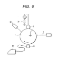
- the electrophotographic photosensitive member having undergone the contact test is set to an apparatus shown in Fig. 6.
- the electrophotographic photosensitive member 1 is caused to rotate in the direction of the arrow with a not-shown motor and is charged uniformly with a charging unit 2.
- a power source 32 in which direct currents are superimposed onto alternate currents is used.
- Reference numeral 3 denotes exposing light
- reference numeral 51 denotes a surface potentiometer which is arranged to be able to record surface potentials continuously with a recording apparatus 53.
- Reference numeral 52 denotes a pre-exposing means, which erase electric charges with intensive exposing prior to charging.
- the electrophotographic photosensitive member 1 is caused to rotate at a peripheral speed of 120 mm/s, and without use of exposing light 3 but with pre-exposing means 52 being used, the voltage of the charging unit 2 is adjusted so that the surface potential of the non-contacting portion is approximately -600V.
- Changes in the surface potential of electrophotographic photosensitive member at this time are recorded with the recording apparatus 53 to cover five rotations of the electrophotographic photosensitive member at an interval of 0.002 second.
- emitting intensity of the exposing light 3 is adjusted so that the surface potential will be -150V. Changes of potential are then recorded in the same manner as in the dark portion potential and calculated.
- This value which falls within the region of not more than ⁇ 20%, can be said to fall within the range of the present invention.
- Super high resistance meter R8340A (produced by Advantest) is used as resistance meter, and as for the test sample box, a test sample box for a super high resistance meter TR42 (produced by Advantest) is used, but the main electrode is set to have a diameter of 25 mm while the guard ring electrode is set to have an inner diameter of 41 mm and an outer diameter of 49 mm.
- the intermediate transfer belt is cut out into a disk of diameter of 56 mm with a puncher or a sharp knife.
- a one face of the disk piece cut out is provided with an electrode all over its face with a Pt-Pd vapor-deposition film, and the other face is provided with a main electrode having a diameter of 25 mm and a guard electrode having an inner diameter of 38 mm and an outer diameter of 50 mm with Pt-Pd vapor-deposition film.
- the Pt-Pd vapor-deposition film is obtained by carrying out the deposition operation for two minutes with the mild sputter E1030 (produced by Hitachi, Ltd.).
- Measuring atmosphere is set to be 23°C/55%RH and the measuring samples are in advance left to stand in the above described measuring atmosphere for not less than 12 hours.
- discharge lasts for 10 seconds
- charging lasts for 30 seconds
- measuring lasts for 30 seconds
- measuring is carrying out with the application voltage of 100 V.
- part(s) is part(s) by weight.
- An aluminum cylinder of diameter of 47 mm and length of 270 mm was provided with a conductive layer of film thickness of 20 ⁇ m made of conductive metal oxide and phenol resin by way of dipping coating.
- the intermediate layer of film thickness of 1 ⁇ m made of methoxymethylated nylon was applied on the above described conductive layer, and moreover, a charge generation layer of film thickness of 0.05 ⁇ m containing gallium phthalocyanine as charge generation material was formed thereon by way of dipping coating.
- a charge transport layer of film thickness of 20 ⁇ m made of 0.9 parts of charge transporting material having the structure shown in the following formula (1), 8.1 parts of charge transporting material having the structure shown in the following formula (2) and 10 parts of the polyarylate resin was provided on the above described charge generation layer also by way of dipping coating so that an electrophotographic photosensitive member 1 in rigid drum shape of diameter of approximately 47 mm.
- An intermediate transfer belt was manufactured with the following materials.
- the above described molding raw material 1 was constructed to use polyetheresteramide being resistance adjusting agent of high molecular weight hardly giving rise to movement (relocation) of matters for fulfilling the above described features of the present invention and moreover to add zinc oxide as a non-active inorganic powder so that contact area with the electrophotographic photosensitive member is reduced.
- the molding die 103 was a circular die for single layer with diameter of 100 mm and the slit was set to 0.8 mm.
- the molten product was extruded into a cylinder shape at 210°C from the die.
- An external cooling ring 105 is disposed around the die, and air was blown from the circumference onto the extruded film to effect cooling.
- the air was blown into the interior of the extruded tubular film from the gas inlet passage 104 to cause the film to inflate while scaling up to have a diameter of 140 mm. Thereafter, the film was continuously drawn off at a constant speed with a draw-off unit.
- thickness of the film was adjusted to 100 ⁇ m. Incidentally, introduction of the air was stopped at the time when the diameter reached the desired value.
- the tubular film was cut with a cutter 108.
- the film was cut in a length of 290 mm after the thickness was stabilized to form a tubular film 1.
- the size and surface smoothness were regulated and folds were removed by means of a set of cylindrical molds made of metals with different thermal expansion coefficient.
- tubular film 1 was placed over and around the internal mold with a higher thermal expansion coefficient.
- the internal mold covered with the above described film 1 was inserted into the external mold with the inner face having been processed into a smooth face followed by heating at 170°C for 40 minutes. Also at this time, removal of the volatile components and low molecular weight components was promoted.
- the tubular film 1 was removed from the mold to cut the ends away and an meandering-preventing member made of urethane elastomer was attached to the rear face of the end to produce an intermediate transfer belt 1 with a diameter of 140 mm, length of 250 mm and thickness of 100 ⁇ m.
- the samples used in the contact tests consisted of three respectively for image confirmation, for surface crack confirmation and for potential confirmation as a set.
- Fig. 7 The unit construction is roughly divided into two parts in Fig. 7.
- One is an electrophotographic photosensitive member unit 50 shown in Fig. 8.
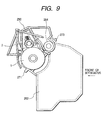
- the other is an intermediate transfer belt unit 251 shown in Fig. 9.
- the intermediate transfer belt 5 is placed over and around the intermediate transfer belt frame 245 with the secondary transfer facing roller 8 and a tension roller (following roller) 12, and primary transfer means (primary transfer roller) 258 disposed inside the intermediate transfer belt facing the electrophotographic photosensitive member 1 and charge providing means 9 disposed relative to the secondary transfer facing roller (drive roller) 8.
- the secondary transfer facing roller (drive roller) 8 has function as a drive roller to rotate the intermediate transfer belt 5.
- protrusions 271 provided in the both right and left ends of the electrophotographic photosensitive member frame 259 are respectively inserted into the positioning holes 272 provided in the intermediate transfer belt frame 245, and on the other hand, a nail 273 of hook part of a snap fit form provided in the center of the width direction of the electrophotographic photosensitive member frame 259 is engaged into a lock hole 274 of the intermediate transfer frame 245 for connection.
- the positioning holes 272 provided in the intermediate transfer frame 245, and the lock hole 274 are provided with holes sized larger by a predetermined quantity than the protrusions 271 provided in the electrophotographic photosensitive member frame 259 and the hook part nail 273, and are constructed to permit relative positional movements of a predetermined amount between the electrophotographic photosensitive member unit 250 and the intermediate transfer belt unit 251.
- positioning holes 272 are provided with taper parts 272a for easy attachment/detachment.
- the protrusions 271 of the electrophotographic photosensitive member unit 250 are inserted into the positioning holes 272 of the intermediate transfer belt unit 251 and rotation in the opposite direction to the case of removal is implemented and the hook nail 273 is pushed into the lock hole 274 to thereby connect the two units.
- the charge providing means 9 are brought into connection with a not-shown feeder plate, and when the process cartridge is incorporated into the main body of the image forming apparatus, power supply will become possible to the charge providing means 9 from the main body of the image forming apparatus through the not-shown feeder plate. This can serve to electrify the transfer residual toner on the intermediate transfer belt 5 to the opposite polarity against the photosensitive member.
- charge providing means 9 are brought into contact with the intermediate transfer belt 5 disposed freely in a separate/contact state and a bias of a reverse polarity against the electrophotographic photosensitive member 1 is applied so that charges of reverse polarity against the primary transfer are given to the transfer residual toner remaining on the intermediate transfer belt 5 without being transferred onto the transfer material P.
- direct currents with alternate currents were applied in a superimposition.
- the spring pressure of the tension roller (following roller) was 20 N totaling the right and the left parties with the slide amount of 2.5 mm and the diameter of the tension roller (following roller) and the secondary transfer facing roller (drive roller) was 28 mm for use.
- This intermediate transfer belt-electrophotographic photosensitive member integrated process cartridge was disposed in the electrophotographic apparatus shown in Fig. 1, and full color image print test was carried out to 80 g/m 2 paper under the same environment.
- the developing apparatus used at this occasion was set to adopt 600 dpi digital laser system.
- the obtained image was evaluated visually, giving rise to good full color image without any problem such as color unevenness as well as faulty transfer.
- the intermediate transfer belt 1 was brought into resistance measuring with the test method of the present invention, resulting in the volume resistance value (volume resistivity) being 9.8 ⁇ 10 11 ⁇ cm.
- the test method was to transport a not yet used process cartridge between Tokyo and Sydney by sea, and thereafter by airmail on the way back so as to confirm existence of occurrence of problems at the time of transportation with high temperature and high humidity environment on a ship and transportation by air being simultaneously executed.
- the collected process cartridge After transportation, the collected process cartridge underwent a likewise print test as described above, an image without any problem was obtained as well, proving its performance without any problems even after long-term transportation.
- An intermediate transfer belt 2 was produced in the same manner as in Example 1 except that composition ratio was changed as follows.
- Polyvinylidene fluoride resin (PVDF) 100 parts
- Polyetheresteramide (Pelestat NC6321: Produced by Sanyo Chemical Industries, Ltd.) 8 parts Perfluorobutane sulfonic acid potassium 2 parts
- Perfluorobutane sulfonic acid potassium was featured by its aptness not to be deposited on the surface of the intermediate transfer belt under high temperature and high humidity with low water solubility in salts and its compatibility with polyvinyliden fluoride resin (PVDF) because of containing fluorine.
- PVDF polyvinyliden fluoride resin
- Composition ratio was changed as follows, and in accordance with the resin, mixing as well as molding and mold heating temperature were raised to 260°C. In addition, in molding processing, inner coarseness on the face of the outer mold was changed to become slightly coarse. Otherwise, an intermediate'transfer belt 3 was produced in the same manner as Example 1.
- the conductive agent in the present example is carbon black, being featured by exclusion of organic matter of low molecular weight badly affecting in particular the electrophotographic photosensitive member.
- Example 1 On the intermediate transfer belt 3, measurement on properties, image print test and transportation test were carried out in the same manner as in Example 1. The results thereof were as good as in Example 1.
- An electrophotographic photosensitive member 2 was produced in the same manner as in Example 1 except that polycarbonate Z was used instead of polyarylate. Except that this electrophotographic photosensitive member 2 was used, measurement on properties, image print test and transportation test were carried out in the same manner as in Example 1. The results thereof were as good as in Example 1.
- a comparative intermediate transfer belt 1 was produced in the same manner as in Example 1 except that composition ratio was changed as follows.
- Polyvinylidene fluoride resin 100 parts
- Polyetheresteramide (Pelestat NC6321: Produced by Sanyo Chemical Industries, Ltd.) 20 parts Perfluorobutane sulfonic acid 4 parts
- Dioctyl phthalate (plastic agent) 1 part
- Example 1 On the comparative intermediate transfer belt 1, tests as in Example 1 and the image print test were carried out. As the result, a small number of cracks of length of 0.5 to 0.8 ⁇ m occurred on the electrophotographic photosensitive member which underwent the contact test of 10 hours, and moreover, a number of cracks of length of 30 to 150 ⁇ m were discovered on the electrophotographic photosensitive member which underwent the contact test of 336 hours.
- Composition ratio of the intermediate transfer belt was changed as follows, and after respective materials were mixed well and were poured into centrifugal molding mold and were rotated while the solvent was evaporated and underwent urethane forming reaction, and thereby a belt made of urethane elastomer of diameter of 140 mm and thickness of 500 ⁇ m by way of centrifugal molding method, and subject to end cutting as well as with meandering-preventing rib being stuck, a comparative intermediate transfer belt 2 was produced.
- Polyester polyol (synthesized from adipic acid and butylenes glycol) 100 parts Isocyanate (tolylene diisocynanate (TDI)) 20 parts Conductive carbon black 20 parts Methyl isobutyl ketone (solvent) 100 parts
- Example 2 On the comparative intermediate transfer belt 2, measurement of properties as in Example 1 and the image print test were carried out. As the result a number of cracks of 3 to 12 ⁇ m were discovered in the portion where the electrophotographic photosensitive member which underwent the contact leaving test of 10 hours and the intermediate transfer belt were brought into contact.
- the electrophotographic photosensitive member left standing for 336 hours has a number of cracks of 500 to 800 ⁇ m in the intermediate transfer belt contact part, and since a small number of cracks of length about 15 to 30 ⁇ m occurred also in the vicinity of the intermediate transfer belt contact part, even the portion where no direct contact takes place is also influenced by the evaporated components such as solvent.
- the process cartridge subject to transportation test also gave rise to such a phenomenon as described above, and was found out to be unable to endure long-period transportation.
- a process cartridge that makes maintenance easy, can plan miniaturization as well as cost reduction of the apparatus to/from which it is attached/removed and makes good images available and an electrophotographic apparatus having the process cartridge can be provided.
- a process cartridge which is detachably mountable to a main body of an electrophotographic apparatus, including an electrophotographic photosensitive member to carry a toner image; an intermediate transfer belt having a contact part with the photosensitive member, and a primary transfer unit to primarily transfer the toner image at the contact part from the photosensitive member to the intermediate transfer belt, being integrally supported in one body.
Landscapes
- Physics & Mathematics (AREA)
- General Physics & Mathematics (AREA)
- Engineering & Computer Science (AREA)
- Computer Vision & Pattern Recognition (AREA)
- Life Sciences & Earth Sciences (AREA)
- Manufacturing & Machinery (AREA)
- Sustainable Development (AREA)
- Electrostatic Charge, Transfer And Separation In Electrography (AREA)
- Electrophotography Configuration And Component (AREA)
Applications Claiming Priority (2)
| Application Number | Priority Date | Filing Date | Title |
|---|---|---|---|
| JP2001263905 | 2001-08-31 | ||
| JP2001263905 | 2001-08-31 |
Publications (2)
| Publication Number | Publication Date |
|---|---|
| EP1288742A2 true EP1288742A2 (fr) | 2003-03-05 |
| EP1288742A3 EP1288742A3 (fr) | 2013-01-16 |
Family
ID=19090588
Family Applications (1)
| Application Number | Title | Priority Date | Filing Date |
|---|---|---|---|
| EP02019502A Withdrawn EP1288742A3 (fr) | 2001-08-31 | 2002-08-30 | Unité de traitement et appareil électrophotographique |
Country Status (2)
| Country | Link |
|---|---|
| US (1) | US6795667B2 (fr) |
| EP (1) | EP1288742A3 (fr) |
Cited By (1)
| Publication number | Priority date | Publication date | Assignee | Title |
|---|---|---|---|---|
| US9411316B2 (en) | 2014-06-19 | 2016-08-09 | Société Anonyme de la Manufacture d'Horlogerie Audemars Piguet & Cie | Tilting coupling device for timepiece |
Families Citing this family (6)
| Publication number | Priority date | Publication date | Assignee | Title |
|---|---|---|---|---|
| US7060030B2 (en) * | 2002-01-08 | 2006-06-13 | Cardiac Pacemakers, Inc. | Two-hop telemetry interface for medical device |
| US6928256B2 (en) * | 2002-09-30 | 2005-08-09 | Canon Kabushiki Kaisha | Electrophotographic endless belt, process cartridge, and electrophotographic apparatus |
| JP2004271943A (ja) * | 2003-03-10 | 2004-09-30 | Konica Minolta Holdings Inc | 画像形成装置 |
| KR101090057B1 (ko) * | 2007-02-20 | 2011-12-07 | 삼성전자주식회사 | 화상형성장치 및 그 벨트 클리닝 유닛 |
| US8064812B2 (en) * | 2008-04-04 | 2011-11-22 | Lexmark International, Inc. | Toner transfer belt with textured surface for enhanced transfer and method of forming textured surface |
| JP5424795B2 (ja) * | 2008-10-27 | 2014-02-26 | キヤノン株式会社 | 帯電部材及びその製造方法、プロセスカートリッジ及び電子写真装置 |
Family Cites Families (23)
| Publication number | Priority date | Publication date | Assignee | Title |
|---|---|---|---|---|
| JPS61279871A (ja) | 1985-06-06 | 1986-12-10 | Canon Inc | 画像形成装置 |
| US5256512A (en) | 1987-01-19 | 1993-10-26 | Canon Kabushiki Kaisha | Color toner and two-component developer containing same |
| US5164275A (en) | 1987-01-19 | 1992-11-17 | Canon Kabushiki Kaisha | Method of forming a multicolor image with color toner and two-component developer containing same |
| US5149610A (en) | 1987-01-19 | 1992-09-22 | Canon Kabushiki Kaisha | Color toner and two-component developer containing same |
| EP0275636B1 (fr) | 1987-01-19 | 1993-07-21 | Canon Kabushiki Kaisha | Agent de contraste coloré et développateur à deux composants, le contenant |
| US5331373A (en) | 1992-03-13 | 1994-07-19 | Canon Kabushiki Kaisha | Image forming apparatus, process cartridge mountable within it and method for attaching photosensitive drum to process cartridge |
| JP3352155B2 (ja) | 1992-06-30 | 2002-12-03 | キヤノン株式会社 | プロセスカートリッジ及び画像形成装置 |
| JPH06110261A (ja) | 1992-09-25 | 1994-04-22 | Ricoh Co Ltd | カラー画像形成装置 |
| US5966566A (en) | 1993-03-24 | 1999-10-12 | Canon Kabushiki Kaisha | Recycle method for process cartridge and image forming apparatus |
| JPH07140874A (ja) | 1993-06-25 | 1995-06-02 | Canon Inc | 像担持体の取付部材及び像担持体の取付方法及びプロセスカートリッジ及び画像形成装置 |
| US5752131A (en) | 1993-06-25 | 1998-05-12 | Canon Kabushiki Kaisha | Developing apparatus with a removable sealing film and process cartridge and image forming apparatus including such a developing apparatus |
| JPH07302034A (ja) | 1994-03-08 | 1995-11-14 | Canon Inc | トナーカートリッジ及びプロセスカートリッジ及び電子写真画像形成装置 |
| JPH07319362A (ja) | 1994-05-19 | 1995-12-08 | Canon Inc | プロセスカートリッジの再生産方法及びプロセスカートリッジ |
| JPH08137181A (ja) | 1994-11-11 | 1996-05-31 | Minolta Co Ltd | 画像形成装置 |
| TW331675B (en) | 1994-12-22 | 1998-05-11 | Canon Kk | Electrophotographic apparatus |
| JPH0950190A (ja) * | 1995-08-04 | 1997-02-18 | Canon Inc | 画像形成装置 |
| JP3490581B2 (ja) | 1996-12-16 | 2004-01-26 | 株式会社リコー | プロセスユニット及び画像形成装置 |
| US6408158B1 (en) * | 1997-01-31 | 2002-06-18 | Seiko Epson Corporation | Intermediate transfer unit |
| JPH1130944A (ja) | 1997-07-10 | 1999-02-02 | Ricoh Co Ltd | プロセスカートリッジユニット及びその着脱構造 |
| JP3608646B2 (ja) * | 1997-07-18 | 2005-01-12 | 株式会社リコー | 画像形成装置及びその装置に用いられる中間転写ユニット |
| JP2000227688A (ja) * | 1999-02-05 | 2000-08-15 | Ricoh Co Ltd | プロセスユニット及びそのプロセスユニットを有する画像形成装置 |
| JP2000227727A (ja) * | 1999-02-05 | 2000-08-15 | Canon Inc | 画像形成装置 |
| JP2000289080A (ja) * | 1999-04-12 | 2000-10-17 | Canon Inc | 電子写真用シームレスベルト及びその製造方法 |
-
2002
- 2002-08-30 EP EP02019502A patent/EP1288742A3/fr not_active Withdrawn
- 2002-08-30 US US10/231,352 patent/US6795667B2/en not_active Expired - Fee Related
Cited By (1)
| Publication number | Priority date | Publication date | Assignee | Title |
|---|---|---|---|---|
| US9411316B2 (en) | 2014-06-19 | 2016-08-09 | Société Anonyme de la Manufacture d'Horlogerie Audemars Piguet & Cie | Tilting coupling device for timepiece |
Also Published As
| Publication number | Publication date |
|---|---|
| US20030118369A1 (en) | 2003-06-26 |
| US6795667B2 (en) | 2004-09-21 |
| EP1288742A3 (fr) | 2013-01-16 |
Similar Documents
| Publication | Publication Date | Title |
|---|---|---|
| US8050604B2 (en) | Belt member and image forming apparatus using the belt member | |
| US6961529B2 (en) | Charging device using a charge roller and image forming apparatus including the same | |
| US20090148201A1 (en) | Belt member, transfer unit incorporating same, image forming apparatus incorporating same, and method of evaluating same | |
| US6725002B2 (en) | Process cartridge, electrophotographic apparatus and image forming method | |
| US6775494B2 (en) | Process cartridge, image forming apparatus and intermediate transfer belt | |
| US6615015B2 (en) | Process cartridge, electrophotographic apparatus and image-forming method | |
| EP2818939B1 (fr) | Ensemble de courroie, appareil de formation d'image et procédé de fabrication de l'ensemble de courroie | |
| US6795667B2 (en) | Process cartridge and electrophotographic apparatus having an intermediate transfer belt | |
| EP3896526B1 (fr) | Appareil de formation d'images | |
| US7536134B2 (en) | Image holding member and image forming apparatus | |
| JP2004029534A (ja) | プロセスカートリッジ及び画像形成装置 | |
| US6852400B2 (en) | Endless belt electrophotography, process for producing the endless belt, and image forming apparatus having the endless belt | |
| US6766127B2 (en) | Image forming apparatus having process cartridge with intermediate transfer belt | |
| JP3273400B2 (ja) | 画像形成装置 | |
| JP2003287964A (ja) | 中間転写ベルト、中間転写ベルト−電子写真感光体ドラム一体カートリッジ、画像形成装置及び画像形成方法 | |
| JP3913137B2 (ja) | 中間転写ベルト、中間転写ベルト−電子写真感光体一体型カートリッジ及び電子写真装置 | |
| JP2003162157A (ja) | プロセスカートリッジ、電子写真装置および中間転写ベルト | |
| JP2002251081A (ja) | 潜像担持体−中間転写回転体一体型カートリッジ及び画像形成装置及び画像形成方法 | |
| JP2002328543A (ja) | プロセスカートリッジ、画像形成装置及び中間転写ベルト | |
| JP7606674B2 (ja) | 画像形成装置 | |
| JP3935395B2 (ja) | プロセスカートリッジ、電子写真装置、画像形成装置、および、中間転写ベルト | |
| JP3943976B2 (ja) | ベルト状転写部材、ベルト状転写部材の製造方法、画像形成装置及び中間転写ベルト−潜像担持体一体型カートリッジ | |
| JP2003316175A (ja) | 中間転写ベルト−電子写真感光体一体型カートリッジ、画像形成装置及び画像形成方法 | |
| JP4136507B2 (ja) | 電子写真用ベルト、画像形成装置及びプロセスカートリッジ | |
| JP2004029533A (ja) | プロセスカートリッジ、電子写真装置、画像形成方法、中間転写ベルト及び電子写真感光体 |
Legal Events
| Date | Code | Title | Description |
|---|---|---|---|
| PUAI | Public reference made under article 153(3) epc to a published international application that has entered the european phase |
Free format text: ORIGINAL CODE: 0009012 |
|
| AK | Designated contracting states |
Kind code of ref document: A2 Designated state(s): AT BE BG CH CY CZ DE DK EE ES FI FR GB GR IE IT LI LU MC NL PT SE SK TR Designated state(s): AT BE BG CH CY CZ DE DK EE ES FI FR GB GR IE IT LI LU MC NL PT SE SK TR |
|
| AX | Request for extension of the european patent |
Extension state: AL LT LV MK RO SI |
|
| 17P | Request for examination filed |
Effective date: 20051017 |
|
| PUAL | Search report despatched |
Free format text: ORIGINAL CODE: 0009013 |
|
| AK | Designated contracting states |
Kind code of ref document: A3 Designated state(s): AT BE BG CH CY CZ DE DK EE ES FI FR GB GR IE IT LI LU MC NL PT SE SK TR |
|
| AX | Request for extension of the european patent |
Extension state: AL LT LV MK RO SI |
|
| RIC1 | Information provided on ipc code assigned before grant |
Ipc: G03G 21/18 20060101AFI20121211BHEP |
|
| 17Q | First examination report despatched |
Effective date: 20130218 |
|
| AKX | Designation fees paid |
Designated state(s): DE FR GB IT |
|
| STAA | Information on the status of an ep patent application or granted ep patent |
Free format text: STATUS: THE APPLICATION HAS BEEN WITHDRAWN |
|
| 18W | Application withdrawn |
Effective date: 20140108 |