EP1288928A2 - Objektivlinse, optisches Abtastgerät und Verfahren zur Herstellung eines optischen Elements für ein optisches Abtastgerät - Google Patents
Objektivlinse, optisches Abtastgerät und Verfahren zur Herstellung eines optischen Elements für ein optisches Abtastgerät Download PDFInfo
- Publication number
- EP1288928A2 EP1288928A2 EP02255758A EP02255758A EP1288928A2 EP 1288928 A2 EP1288928 A2 EP 1288928A2 EP 02255758 A EP02255758 A EP 02255758A EP 02255758 A EP02255758 A EP 02255758A EP 1288928 A2 EP1288928 A2 EP 1288928A2
- Authority
- EP
- European Patent Office
- Prior art keywords
- information recording
- optical
- recording medium
- light flux
- light source
- Prior art date
- Legal status (The legal status is an assumption and is not a legal conclusion. Google has not performed a legal analysis and makes no representation as to the accuracy of the status listed.)
- Granted
Links
Images


Classifications
-
- G—PHYSICS
- G11—INFORMATION STORAGE
- G11B—INFORMATION STORAGE BASED ON RELATIVE MOVEMENT BETWEEN RECORD CARRIER AND TRANSDUCER
- G11B7/00—Recording or reproducing by optical means, e.g. recording using a thermal beam of optical radiation by modifying optical properties or the physical structure, reproducing using an optical beam at lower power by sensing optical properties; Record carriers therefor
- G11B7/12—Heads, e.g. forming of the optical beam spot or modulation of the optical beam
- G11B7/135—Means for guiding the beam from the source to the record carrier or from the record carrier to the detector
- G11B7/1392—Means for controlling the beam wavefront, e.g. for correction of aberration
- G11B7/13922—Means for controlling the beam wavefront, e.g. for correction of aberration passive
-
- G—PHYSICS
- G02—OPTICS
- G02B—OPTICAL ELEMENTS, SYSTEMS OR APPARATUS
- G02B13/00—Optical objectives specially designed for the purposes specified below
-
- G—PHYSICS
- G02—OPTICS
- G02B—OPTICAL ELEMENTS, SYSTEMS OR APPARATUS
- G02B5/00—Optical elements other than lenses
- G02B5/18—Diffraction gratings
-
- G—PHYSICS
- G11—INFORMATION STORAGE
- G11B—INFORMATION STORAGE BASED ON RELATIVE MOVEMENT BETWEEN RECORD CARRIER AND TRANSDUCER
- G11B7/00—Recording or reproducing by optical means, e.g. recording using a thermal beam of optical radiation by modifying optical properties or the physical structure, reproducing using an optical beam at lower power by sensing optical properties; Record carriers therefor
- G11B7/12—Heads, e.g. forming of the optical beam spot or modulation of the optical beam
- G11B7/125—Optical beam sources therefor, e.g. laser control circuitry specially adapted for optical storage devices; Modulators, e.g. means for controlling the size or intensity of optical spots or optical traces
- G11B7/127—Lasers; Multiple laser arrays
-
- G—PHYSICS
- G11—INFORMATION STORAGE
- G11B—INFORMATION STORAGE BASED ON RELATIVE MOVEMENT BETWEEN RECORD CARRIER AND TRANSDUCER
- G11B7/00—Recording or reproducing by optical means, e.g. recording using a thermal beam of optical radiation by modifying optical properties or the physical structure, reproducing using an optical beam at lower power by sensing optical properties; Record carriers therefor
- G11B7/12—Heads, e.g. forming of the optical beam spot or modulation of the optical beam
- G11B7/135—Means for guiding the beam from the source to the record carrier or from the record carrier to the detector
- G11B7/1353—Diffractive elements, e.g. holograms or gratings
-
- G—PHYSICS
- G11—INFORMATION STORAGE
- G11B—INFORMATION STORAGE BASED ON RELATIVE MOVEMENT BETWEEN RECORD CARRIER AND TRANSDUCER
- G11B7/00—Recording or reproducing by optical means, e.g. recording using a thermal beam of optical radiation by modifying optical properties or the physical structure, reproducing using an optical beam at lower power by sensing optical properties; Record carriers therefor
- G11B7/12—Heads, e.g. forming of the optical beam spot or modulation of the optical beam
- G11B7/135—Means for guiding the beam from the source to the record carrier or from the record carrier to the detector
- G11B7/1372—Lenses
- G11B7/1374—Objective lenses
-
- G—PHYSICS
- G11—INFORMATION STORAGE
- G11B—INFORMATION STORAGE BASED ON RELATIVE MOVEMENT BETWEEN RECORD CARRIER AND TRANSDUCER
- G11B7/00—Recording or reproducing by optical means, e.g. recording using a thermal beam of optical radiation by modifying optical properties or the physical structure, reproducing using an optical beam at lower power by sensing optical properties; Record carriers therefor
- G11B2007/0003—Recording, reproducing or erasing systems characterised by the structure or type of the carrier
- G11B2007/0006—Recording, reproducing or erasing systems characterised by the structure or type of the carrier adapted for scanning different types of carrier, e.g. CD & DVD
Definitions
- the present invention relates to an optical pickup device and an objective lens to be used in the optical pickup, and in particular, to an objective lens of an optical pickup device capable of conducting recording and/or reproducing of information for optical information recording media each being different by using a plurality of light sources each having a different wavelength, an optical pickup device and to a method for designing an optical element for the optical pickup device.
- an optical pickup device capable of recording and reproducing information for optical information recording media each being different in terms of type such as, for example, DVD and CD
- the optical pickup device is now used for various purposes.
- a light source of the optical pickup device in this case, a semiconductor laser is used in general, and appropriate wavelength ⁇ to be used for recording or reproducing information for DVD is about 650 nm, while, appropriate wavelength ⁇ to be used for recording or reproducing information for CD is about 780 nm.
- a thickness of a transparent base board (also called a protection base board) that protects the image recording surface of a standardized DVD is 0.6 mm
- a thickness of a transparent base board that protects the image recording surface of CD is 1.2 mm. Therefore, when the information recording surface of each of DVD and CD is irradiated by a light flux emitted from the light source through the same objective lens, there is the actual state of affairs that a distance from CD to the objective lens needs to be shorter than that from DVD to the objective lens, because of the difference of the transparent base board thickness.
- a distance from the objective lens to the surface of the optical information recording medium in this case, is called a working distance.
- an individual subject distance is set for using, for example, DVD and CD. Namely, by making a divergent angle or a convergent angle of a light flux (including a parallel light flux) that enters an objective lens to be different between an occasion to use DVD and an occasion to use CD, it is possible to make working distances for both occasions to agree with each other approximately.
- the distance between the objective lens to one light source needs to be different from that from the objective lens to the other light source, and the structure of the optical system becomes complicated. The problem of this kind is especially conspicuous when an optical pickup device is structured by using a light source unit that is called the so-called 2-laser 1-package wherein two light sources each having a different wavelength are formed on one base board.
- the invention has been achieved in view of the problems in the conventional technology, and its object is to provide an objective lens of an optical pickup device which has a simple and compact structure and can conduct recording and/or reproducing of information for optical information recording media each being different by using plural light sources each being different in terms of wavelength, the optical pickup device, and a method of designing an optical element for the optical pickup device.
- Another object of the invention is to provide an objective lens of an optical pickup device capable of making a difference in a working distance to be small for optical information recording media each being different in terms of a transparent base board thickness.
- another object of the invention is to provide an optical pickup device capable of controlling power consumption to be small by making the difference in a working distance to be small.
- the objective lens of the optical pickup device described in Item 1 is represented by an objective lens of an optical pickup device in which recording and/or reproducing of information is possible by making a light flux emitted from the first light source having a wavelength of ⁇ 1 to be converged on an information recording surface of the first optical information recording medium through a protective base board having a thickness of t1, and recording and/or reproducing of information is possible by making a light flux emitted from the second light source having a wavelength of ⁇ 2 ( ⁇ 1 ⁇ ⁇ 2) to be converged on an information recording surface of the second optical information recording medium through a protective base board having a thickness of t2 (t1 ⁇ t2), wherein a diffractive optical surface is formed on either one of optical elements provided in an optical path, and thereby, the light flux emitted from the first light source is converged on the information recording surface of the first optical information recording medium having the thinner protective base board, as a diffracted ray of the first number diffraction order without being of the zero
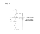
- Fig. 1 is a sectional view showing an enlarged part of the diffractive optical surface formed on a parallel flat plate representing an example of an optical element.
- the diffractive structure of the diffractive optical surface is a serrated ring-shaped zone wherein a width of a ring-shaped zone in the direction perpendicular to an optical axis is represented by pitch p and a depth of a groove of the ring-shaped zone is represented by d.
- pitch p a width of a ring-shaped zone in the direction perpendicular to an optical axis
- d a depth of a groove of the ring-shaped zone
- the power Np varies depending on the number of orders for refraction utilizing a pitch, and it is in the tendency that the higher the number of orders for refraction to be used is, the greater the power Np is.
- depth of a groove of the ring-shaped zone d is related to quantity of light of transmitted light flux as will be described later.
- the structure of the optical system can be made simple.
- a working distance between an objective lens and an optical information recording medium varies depending on the type of the optical information recording medium.
- the problem stated above is lightened or solved by conducting recording and/or reproducing of information by the use of refracted light each being different in terms of order for refraction.
- pitch p and groove depth d of the diffractive ring-shaped zone appropriately, it is possible to make a distance (working distance) from the objective lens to the surface of the first optical information recording medium on the occasion when a light flux with wavelength ⁇ 1 is converged, as a diffracted ray of the first number diffraction order, on an information recording surface of the first optical information recording medium and a distance (working distance) from the objective lens to the surface of the first optical information recording medium on the occasion when a light flux with wavelength ⁇ 2 is converged, as a diffracted ray of the second number diffraction order that is lower order than the first number diffraction order, on an information recording surface of the second optical information recording medium, to be closer each other or to agree with each other.
- a light flux emitted from the first light source is converged on the first optical information recording medium having the thinner protective base board, as a diffracted ray of the first number diffraction order
- a light flux emitted from the second light source is converged on the second optical information recording medium having the thicker protective base board, as a diffracted ray of the second number diffraction order that is lower than the first number diffraction order, thus, it is possible to exhibit the effect of the invention described in the Item 1 stated above, more effectively.
- the objective lens of the optical pickup device described in Item 3 is represented by an objective lens of an optical pickup device in which recording and/or reproducing of information is possible by making a light flux emitted from the first light source having a wavelength of ⁇ 1 to be converged on an information recording surface of the first optical information recording medium through a protective base board having a thickness of t1, and recording and/or reproducing of information is possible by making a light flux emitted from the second light source having a wavelength of ⁇ 2 ( ⁇ 1 ⁇ ⁇ 2) to be converged on an information recording surface of the second optical information recording medium through a protective base board having a thickness of t2 (t1 ⁇ t2), wherein a diffractive optical surface is formed on either one of optical elements provided in an optical path of the optical pickup device, and thereby the light flux emitted from the first light source is converged on the optical information recording medium, as a diffracted ray of the first order, and the light flux emitted from the second light source is converged on the
- the objective lens of the optical pickup device described in Item 4 is represented by an objective lens of an optical pickup device in which recording and/or reproducing of information is possible by making a light flux emitted from the first light source having a wavelength of ⁇ 1 to be converged on an information recording surface of the first optical information recording medium through a protective base board having a thickness of t1, and recording and/or reproducing of information is possible by making a light flux emitted from the second light source having a wavelength of ⁇ 2 ( ⁇ 1 ⁇ ⁇ 2) to be converged on an information recording surface of the second optical information recording medium through a protective base board having a thickness of t2 (t1 ⁇ t2), wherein a distance from the first light source to the surface of the protective base board of the first optical information recording medium and a distance from the second light source to the surface of the protective base board of the second optical information recording medium are almost the same, and a diffractive optical surface is formed on either one of optical elements provided in the optical path, and a light flux from the first
- the objective lens of the optical pickup device described in Item 5 is represented by an objective lens of an optical pickup device in which recording and/or reproducing of information is possible by making a light flux emitted from the first light source having a wavelength of ⁇ 1 to be converged on an information recording surface of the first optical information recording medium through a protective base board having a thickness of t1, and recording and/or reproducing of information is possible by making a light flux emitted from the second light source having a wavelength of ⁇ 2 ( ⁇ 1 ⁇ ⁇ 2) to be converged on an information recording surface of the second optical information recording medium through a protective base board having a thickness of t2 (t1 ⁇ t2), wherein light fluxes from the first light source and from the second light source are both a finite light flux or an infinite light flux and enter the objective lens, a diffractive optical surface is provided on either one of optical elements provided in the optical path, the light flux from the first light source is converged by the diffractive optical surface on the optical information recording medium as
- the diffractive optical surface has a diffracting characteristic to make the focal length relating to a light flux with a longer wavelength ⁇ 2 to be greater than the focal length relating to a light flux with a shorter wavelength ⁇ 1. It is therefore possible to attain the effect to make the working distance to be closer each other or to agree with each other.
- DVD represents the first optical information recording medium
- CD represents the second optical information recording medium
- D3 representing a distance from the objective lens to the CD surface in the case of converging properly the second order diffracted ray (same diffraction order as for DVD) of a light flux
- the structure can further be simplified, compared with an occasion to provide these light sources separately.
- the optical pickup device described in Item 8 is represented by an optical pickup device in which a first light source with a wavelength of ⁇ 1, a second light source with a wavelength of ⁇ 2 ( ⁇ 1 ⁇ ⁇ 2) and a light converging optical system are provided, and when a light flux from the first light source is converged by the light converging optical system on the information recording surface of the first optical information recording medium through a protective base board having a thickness of t1, recording and/or reproducing of information is possible, and when a light flux from the second light source is converged by the light converging optical system on the information recording surface of the second optical information recording medium through a protective base board having a thickness of t2 (t1 ⁇ t2), recording and/or reproducing of information is possible, wherein, a diffractive optical surface is formed on either one of optical elements provided in the optical path, and a light flux from the first light source is converged on the information recording surface of the first optical information recording medium having a thinner protective base board as a diff
- a light flux from the first light source is converged on the fist optical information recording medium having a thinner protective base board as a diffracted ray of the first number diffraction order
- a light flux from the second light source is converged on the second optical information recording medium having a thicker protective base board as a diffracted ray of the second number diffraction order that is lower than the first number diffraction order.
- the optical pickup device of the invention exhibits action and effect which are the same as those of the invention described in Item 2.
- the optical pickup device described in Item 10 is represented by an optical pickup device in which a first light source with a wavelength of ⁇ 1, a second light source with a wavelength of ⁇ 2 ( ⁇ 1 ⁇ ⁇ 2) and a light converging optical system are provided, and when a light flux from the first light source is converged by the light converging optical system on the information recording surface of the first optical information recording medium through a protective base board having a thickness of t1, recording and/or reproducing of information is possible, and when a light flux from the second light source is converged by the light converging optical system on the information recording surface of the second optical information recording medium through a protective base board having a thickness of t2 (t1 ⁇ t2), recording and/or reproducing of information is possible, wherein, a diffractive optical surface is formed on either one of optical elements provided in the optical path of the optical pickup device, and a light flux from the first light source is converged on the optical information recording medium as a diffracted ray of the first number
- the optical pickup device described in Item 11 is represented by an optical pickup device in which a first light source with a wavelength of ⁇ 1, a second light source with a wavelength of ⁇ 2 ( ⁇ 1 ⁇ ⁇ 2) and a light converging optical system are provided, and when a light flux from the first light source is converged by the light converging optical system on the information recording surface of the first optical information recording medium through a protective base board having a thickness of t1, recording and/or reproducing of information is possible, and when a light flux from the second light source is converged by the light converging optical system on the information recording surface of the second optical information recording medium through a protective base board having a thickness of t2 (t1 ⁇ t2), recording and/or reproducing of information is possible, wherein, a distance from the first light source to the surface of the protective base board of the first optical information recording medium is mostly the same as a distance from the second light source to the surface of the protective base board of the second optical information recording medium, a diffractive optical
- the optical pickup device described in Item 12 is represented by an optical pickup device in which a first light source with a wavelength of ⁇ 1, a second light source with a wavelength of ⁇ 2 ( ⁇ 1 ⁇ ⁇ 2) and a light converging optical system are provided, and when a light flux from the first light source is converged by the light converging optical system on the information recording surface of the first optical information recording medium through a protective base board having a thickness of t1, recording and/or reproducing of information is possible, and when a light flux from the second light source is converged by the light converging optical system on the information recording surface of the second optical information recording medium through a protective base board having a thickness of t2 (t1 ⁇ t2), recording and/or reproducing of information is possible, wherein, light fluxes from the first light source and from the second light source are both a finite light flux or an infinite light flux and enter the objective lens, a diffractive optical surface is provided on either one of optical elements provided in the optical path, the light flux
- the structure of the light converging optical system can further be simplified, because the light flux from the first light source and the light flux from the second light source enter the objective lens as infinite light or finite light.
- the optical pickup device of the invention exhibits action and effect which are the same as those of the invention described in Item 5.
- the diffractive optical surface has a diffracting characteristic to make the focal length relating to a light flux with a longer wavelength ⁇ 2 to be greater than the focal length relating to a light flux with a shorter wavelength ⁇ 1.
- the optical pickup device of the invention exhibits action and effect which are the same as those of the invention described in Item 6.
- the first light source and the second light source are arranged on the same base board.
- the optical pickup device of the invention exhibits action and effect which are the same as those of the invention described in Item 7.
- a diffraction pitch of the diffractive structure and a diffraction order are established for determining an emergent angle of the light flux passing through the optical element, and a depth of a diffractive groove of the diffractive structure is established for determining quantity of light of the light flux passing through the optical element, when establishing an emergent angle and quantity of light of each light flux which has passed the optical element. Therefore, it is possible to obtain the optical pickup device wherein a difference of the working distance between the occasion of using DVD and the occasion of using CD is controlled to be small, while sufficient quantity of light on the image recording surface is secured.
- a light flux from the first light source is converged, by the diffractive structure, on the information recording surface of the first optical information recording medium having a thinner protective base board as a diffracted ray of the first number diffraction order without being of the zero diffraction order
- a light flux from the second light source is converged, by the diffractive structure, on the information recording surface of the second optical information recording medium having a thicker protective base board as a diffracted ray of the second number diffraction order that is different from the first number diffraction order and is not the zero diffraction order. Therefore, as explained with respect to Item 1, it is possible to obtain the optical pickup device wherein a difference of the working distance between the occasion of using DVD and the occasion of using CD is controlled to be small.
- the method for designing an optical element for the optical pickup device described in Item 17 is represented by a method for designing an optical element for the optical pickup device in which, when a light flux from the first light source with a wavelength of ⁇ 1 is converged on the information recording surface of the first optical information recording medium through a protective base board having a thickness of t1, recording and/or reproducing of information is possible, and when a light flux from the second light source having a wavelength of ⁇ 2 ( ⁇ 1 ⁇ ⁇ 2) is converged on the information recording surface of the second optical information recording medium through a protective base board having a thickness of t2 (t1 ⁇ t2), recording and/or reproducing of information is possible, wherein, for a light flux from the first light source with a wavelength of ⁇ 1 and for a light flux from the second light source with a wavelength of ⁇ 2 ( ⁇ 1 ⁇ ⁇ 2), a diffraction pitch of the diffractive structure and a diffraction order are established for determining an emergent angle of the
- a light flux from the first light source is converged, by the diffractive structure, on the information recording surface of the first optical information recording medium having a thinner protective base board as a diffracted ray of the first number diffraction order without being of the zero diffraction order
- a light flux from the second light source is converged, by the diffractive structure, on the information recording surface of the second optical information recording medium having a thicker protective base board as a diffracted ray of the second number diffraction order that is different from the first number diffraction order and is not the zero diffraction order. Therefore, as explained with respect to Item 1, it is possible to obtain the optical pickup device wherein a difference of the working distance between the occasion of using DVD and the occasion of using CD is controlled to be small.
- the "diffractive optical surface” mentioned in the present specification means an optical surface on which a “diffractive structure” or a “diffractive ring-shaped zone” is formed, and the "diffractive structure” or the “diffractive ring-shaped zone” means a portion wherein a relief is provided on the surface of an optical element such as, for example, an objective lens so that the optical element may have a function to converge or diverge a light flux by diffraction.
- a ring-shaped zone which is almost in a shape of a concentric circle whose center falls on an optical axis, and looks like a saw tooth when its section is viewed on a plane including the optical axis, and such form is especially called "diffractive ring-shaped zone".
- an objective lens in a narrow sense is a lens having a light-converging function which is arranged to face an optical information recording medium at the position closest to the optical information recording medium, under the condition that the optical information recording medium is loaded in the optical pickup device
- an objective lens in a broad sense is a lens that can be operated by an actuator in at least a direction of an optical axis together with the lens in a narrow sense.
- the second optical information recording medium means optical discs of various CD types such as, for example, CD-R, CD-RW, CD-Video and CD-ROM
- the first optical information recording medium means optical discs of various DVD types such as DVD-ROM and DVD-Video used for reproducing only and DVD-RAM, DVD-R and DVD-RW used for both reproducing and recording.
- Fig. 2 is a schematic structural diagram of optical pickup device 100 relating to the embodiment of the invention.
- optical pickup device 100 is provided with optical unit 114 wherein the first light source 111 for conducting recording and/or reproducing for the first optical information recording medium (for example, DVD) and the second light source 112 having a wavelength different from that of the first light source for conducting recording and/or reproducing for the second optical information recording medium (for example, CD) are arranged on the same base board 113, collimator lens 121 for converting a divergent angle of a divergent light flux emitted from each of the light sources 111and 112 into a desired divergent angle, 1/4 wavelength plate 122, objective lens 103 that converges a light flux passing through the collimator lens 121 and the 1/4 wavelength plate 122 on each of information recording surfaces 105 and 105' of optical information recording media, and optical detector 141 that receives reflected light from the optical information recording medium.
- the first optical information recording medium for example, DVD
- the second light source 112 having a wavelength
- the numeral 108 represents a diaphragm
- 107 represents a beam splitter that deflects the reflected light from the information recording surface to the optical detector 141
- the numeral 109 represents a cylindrical lens
- 110 represent a concave lens.
- a parallel light flux is made to enter the objective lens 103 representing an optical element under the same magnification, both in the case of using DVD and of using CD.
- a diffractive ring-shaped zone is formed on the objective lens 203.
- Fig. 3 is a schematic structural diagram of optical pickup device 200 relating to the second embodiment.
- optical pickup device 200 is provided with first light source 211 for conducting recording and/or reproducing for the first optical information recording medium (for example, DVD), second light source 212 with a wavelength different from that of the first light source 211 for conducting recording and/or reproducing for the second optical information recording medium (for example, CD), beam splitter 215 that makes paths of light fluxes from light sources 211 and 212 to agree with each other, collimator lens 221 for converting a divergent angle of a divergent light flux emitted from each of the light sources 211and 212 into a desired divergent angle, 1/4 wavelength plate 222, objective lens 203 that converges a light flux passing through the collimator lens 221 and the 1/4 wavelength plate 222 on each of information recording surfaces 205 and 205' of optical information recording media, and optical detector 241 that receives reflected light from the optical information recording medium.
- first light source 211 for conducting recording and/or reproducing for the
- the numeral 208 represents a diaphragm
- 207 represents a beam splitter that deflects the reflected light from the information recording surface to the optical detector 241
- the numeral 209 represents a cylindrical lens
- 210 represent a concave lens.
- a parallel light flux is made to enter the objective lens 203 representing an optical element under the same magnification, both in the case of using DVD and of using CD.
- a diffractive ring-shaped zone is formed on the objective lens 203.
- Fig. 4 is a schematic structural diagram of optical pickup device 300 relating to the third embodiment.
- optical pickup device 300 is provided with first light source 311 for conducting recording and/or reproducing for the first optical information recording medium (for example, DVD), second light source 312 with a wavelength different from that of the first light source 311 for conducting recording and/or reproducing for the second optical information recording medium (for example, CD), beam splitter 315 that makes paths of light fluxes from light sources 311 and 312 to agree with each other, objective lens 303 that makes divergent light fluxes emitted respectively from the light sources 311 and 312 to be converged respectively on information recording surfaces 305 and 305', and optical detector 341 that receives reflected light from the optical information recording medium.
- the numeral 308 represents a diaphragm
- 307 represents a beam splitter that deflects the reflected light from the information recording surface to the optical detector 341 and 316 represent an astigmatism generating plate.
- an arrangement is made so that a divergent light flux is made to enter the objective lens 303 representing an optical element under the same magnification, even in the case of using DVD and CD.
- a diffractive ring-shaped zone is formed on the objective lens 303.
- Example 1 explained below is one relating to the objective lens that can be applied to the third Embodiment mentioned above.
- Table 1 shows lens data of the objective lens in Example 1.
- a second order diffracted ray is used as the first number diffraction order diffracted ray for recording or reproducing information of DVD
- a first order diffracted ray is used as the second number diffraction order diffracted ray for recording or reproducing information of CD.
- an exponent of 10 for example, 2.5 x 10 -3
- E for example, 2.5 x E-3
- the objective lens in the present example is composed of a plastic lens having an aspheric surface on its both sides, and each aspheric surface has a shape of the aspheric surface expressed by Numeral 1.
- Z represents an axis in the direction of an optical axis
- h represents an axis in the direction perpendicular to the optical axis
- r represents a paraxial radius of curvature
- ⁇ represents the constant of the cone
- A represents the aspheric surface coefficient
- the optical path difference function ⁇ is expressed by Numeral 2 with a unit of mm.
- m represents a diffraction order.
- Numeral 3 is a conditional expression to create a shape of diffraction.
- ⁇ BDVD represents a wavelength of a light source in using DVD and m DVD represents a diffraction order in using DVD
- ⁇ BCD represents a wavelength of a light source in using CD
- m CD represents a diffraction order in using CD
- C 2DVD represents the coefficient of the second degree of the optical path difference function of DVD
- C 2CD represents the coefficient of the second degree of the optical path difference function of CD.
- a difference between working distances in the present example is within a range shown by Numeral 6.
- ⁇ DVD represents refracting power of the objective lens in using DVD
- ⁇ CD represents refracting power of the objective lens in using CD.
- ⁇ t represents a difference (0.6 mm) of a transparent base board between DVD and CD
- n represents a refractive index of the objective lens.
- a distance from the third surface of the objective lens to the surface of the disc is the same (1.196 mm) for both DVD and CD, which is clear from the Table 1. (Numeral 6) 0.05 ⁇ ⁇ t n ⁇ 1 ⁇ DVD - 1 ⁇ CD ⁇ ⁇ t n
- Example 2 explained below is one relating to the objective lens that can be applied to the third Embodiment mentioned above.
- Table 2 shows lens data of the objective lens in Example 2.
- a second order diffracted ray is used as the first number diffraction order diffracted ray for recording or reproducing information of DVD
- a first order diffracted ray is used as the second number diffraction order diffracted ray for recording or reproducing information of CD.
- a distance from the third surface of the objective lens to the surface of the disc for DVD is closer to that for CD, compared with an occasion where the diffracted ray of the same diffraction order is used.
- Example 3 explained below is one relating to the objective lens that can be applied to the third Embodiment mentioned above.
- Table 3 shows lens data of the objective lens in Example 1.
- a third order diffracted ray is used as the first number diffraction order diffracted ray for recording or reproducing information of DVD
- a second order diffracted ray is used as the second number diffraction order diffracted ray for recording or reproducing information of CD.
- a distance from the third surface of the objective lens to the surface of the disc is the same (1.033 mm) for both DVD and CD, which is clear from the Table 3.
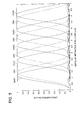
- Fig. 5 is a diagram showing an example of relationship between diffraction groove depth d and diffraction efficiency (quantity of light of diffracted ray). Therefore, it is possible to establish appropriately a quantity of diffracted ray by setting a value of the diffraction order and a value of a diffraction groove depth properly for DVD and CD.
- the invention makes it possible to provide an optical pickup device which is simple and compact in terms of structure, and uses plural light sources each having a different wavelength to conduct recording and/or reproducing information for optical information recording media each being different, and exhibits various effects, an objective lens and a method of manufacturing an optical element.
Landscapes
- Physics & Mathematics (AREA)
- Optics & Photonics (AREA)
- General Physics & Mathematics (AREA)
- Optical Head (AREA)
- Lenses (AREA)
- Diffracting Gratings Or Hologram Optical Elements (AREA)
Applications Claiming Priority (2)
| Application Number | Priority Date | Filing Date | Title |
|---|---|---|---|
| JP2001253798A JP4822037B2 (ja) | 2001-08-24 | 2001-08-24 | 光ピックアップ装置の対物レンズ及び光ピックアップ装置 |
| JP2001253798 | 2001-08-24 |
Publications (3)
| Publication Number | Publication Date |
|---|---|
| EP1288928A2 true EP1288928A2 (de) | 2003-03-05 |
| EP1288928A3 EP1288928A3 (de) | 2007-08-22 |
| EP1288928B1 EP1288928B1 (de) | 2009-07-15 |
Family
ID=19082063
Family Applications (1)
| Application Number | Title | Priority Date | Filing Date |
|---|---|---|---|
| EP02255758A Expired - Lifetime EP1288928B1 (de) | 2001-08-24 | 2002-08-19 | Objektivlinse, optisches Abtastgerät und Verfahren zur Herstellung eines optischen Elements für ein optisches Abtastgerät |
Country Status (7)
| Country | Link |
|---|---|
| US (1) | US7126902B2 (de) |
| EP (1) | EP1288928B1 (de) |
| JP (1) | JP4822037B2 (de) |
| KR (1) | KR100882062B1 (de) |
| CN (1) | CN100487513C (de) |
| DE (1) | DE60232939D1 (de) |
| TW (1) | TW583418B (de) |
Families Citing this family (9)
| Publication number | Priority date | Publication date | Assignee | Title |
|---|---|---|---|---|
| JP2004319062A (ja) * | 2003-03-31 | 2004-11-11 | Konica Minolta Holdings Inc | 光ピックアップ装置 |
| US7193954B2 (en) * | 2003-03-31 | 2007-03-20 | Konica Minolta Holding, Inc. | Optical pickup device and objective lens for the optical pickup device |
| JP4329608B2 (ja) * | 2004-04-23 | 2009-09-09 | コニカミノルタオプト株式会社 | 対物レンズ、光ピックアップ装置及び光情報記録再生装置 |
| JPWO2006001215A1 (ja) | 2004-06-29 | 2008-04-17 | コニカミノルタオプト株式会社 | 光ピックアップシステム |
| EP1736975A1 (de) * | 2005-06-16 | 2006-12-27 | Deutsche Thomson-Brandt Gmbh | Abtastgerät für ein optisches Aufzeichnungsmedium |
| WO2008056577A1 (en) | 2006-11-10 | 2008-05-15 | Sumitomo Electric Industries, Ltd. | Si-O CONTAINING HYDROGENATED CARBON FILM, OPTICAL DEVICE INCLUDING THE SAME, AND METHOD FOR MANUFACTURING THE Si-O CONTAINING HYDROGENATED FILM AND THE OPTICAL DEVICE |
| JP5083621B2 (ja) * | 2008-04-24 | 2012-11-28 | コニカミノルタアドバンストレイヤー株式会社 | 対物レンズ及び光ピックアップ装置 |
| WO2012043506A1 (ja) * | 2010-09-29 | 2012-04-05 | コニカミノルタオプト株式会社 | 光ピックアップ装置用の対物レンズ及び光ピックアップ装置 |
| JP5751328B2 (ja) * | 2011-06-29 | 2015-07-22 | 株式会社ニコン | 構造化照明光学系および構造化照明顕微鏡装置 |
Family Cites Families (16)
| Publication number | Priority date | Publication date | Assignee | Title |
|---|---|---|---|---|
| JP3425845B2 (ja) * | 1995-10-25 | 2003-07-14 | コニカ株式会社 | 光情報記録媒体の記録再生用光学系および対物レンズ |
| JPH09311271A (ja) * | 1996-05-20 | 1997-12-02 | ソニー株式会社 | 対物レンズ及び光学ピックアップ装置 |
| DE69840429D1 (de) | 1997-04-21 | 2009-02-26 | Konica Corp | Optische Abtastvorrichtung |
| JPH11328264A (ja) | 1998-05-12 | 1999-11-30 | Taisei Corp | 病院の診療圏の設定方法 |
| JPH11355788A (ja) | 1998-06-03 | 1999-12-24 | Nikon Corp | 色順次式撮像装置 |
| JP3689266B2 (ja) * | 1998-06-26 | 2005-08-31 | ペンタックス株式会社 | 光ヘッド用対物レンズ |
| US6118594A (en) * | 1998-06-26 | 2000-09-12 | Asahi Kogaku Kogyo Kabushiki Kaisha | Objective lens for optical pick-up |
| JP2000047984A (ja) | 1998-07-28 | 2000-02-18 | Nec Corp | コンピュータシステム及びプログラムを記憶した記憶媒体 |
| JP2937261B1 (ja) | 1998-09-16 | 1999-08-23 | パラマウントベッド株式会社 | チルト機能を備えた頭側ボトムを有するベッド |
| US6834036B1 (en) | 1998-10-28 | 2004-12-21 | Matsushita Electric Industrial Co., Ltd. | Optical head for a plurality of types of information recording media |
| JP2000207766A (ja) * | 1999-01-07 | 2000-07-28 | Sony Corp | 光学ピックアップ装置およびこれを具備する光記録再生装置 |
| JP2001093179A (ja) * | 1999-09-21 | 2001-04-06 | Pioneer Electronic Corp | 光ピックアップ |
| CN1221956C (zh) * | 1999-11-18 | 2005-10-05 | 柯尼卡株式会社 | 光拾取装置及物镜 |
| JP3603002B2 (ja) * | 2000-03-10 | 2004-12-15 | 株式会社三協精機製作所 | 光ピックアップ装置およびその受光方法 |
| EP1320851A1 (de) * | 2000-09-04 | 2003-06-25 | Koninklijke Philips Electronics N.V. | Optisches abtastgerät |
| JP4610118B2 (ja) * | 2001-03-30 | 2011-01-12 | Hoya株式会社 | 光ヘッド用対物レンズ |
-
2001
- 2001-08-24 JP JP2001253798A patent/JP4822037B2/ja not_active Expired - Fee Related
-
2002
- 2002-08-16 TW TW091118570A patent/TW583418B/zh not_active IP Right Cessation
- 2002-08-19 EP EP02255758A patent/EP1288928B1/de not_active Expired - Lifetime
- 2002-08-19 DE DE60232939T patent/DE60232939D1/de not_active Expired - Lifetime
- 2002-08-20 US US10/223,631 patent/US7126902B2/en not_active Expired - Fee Related
- 2002-08-21 CN CNB021304777A patent/CN100487513C/zh not_active Expired - Fee Related
- 2002-08-21 KR KR1020020049362A patent/KR100882062B1/ko not_active Expired - Fee Related
Also Published As
| Publication number | Publication date |
|---|---|
| US20030112528A1 (en) | 2003-06-19 |
| JP4822037B2 (ja) | 2011-11-24 |
| CN1407364A (zh) | 2003-04-02 |
| KR100882062B1 (ko) | 2009-02-10 |
| US7126902B2 (en) | 2006-10-24 |
| KR20030017367A (ko) | 2003-03-03 |
| DE60232939D1 (de) | 2009-08-27 |
| EP1288928A3 (de) | 2007-08-22 |
| JP2003066324A (ja) | 2003-03-05 |
| CN100487513C (zh) | 2009-05-13 |
| TW583418B (en) | 2004-04-11 |
| EP1288928B1 (de) | 2009-07-15 |
Similar Documents
| Publication | Publication Date | Title |
|---|---|---|
| EP1313095B1 (de) | Kompatibles optisches Abstastgerät | |
| US6480455B2 (en) | Optical pickup device applicable to two kinds of recording media with minimized deterioration of a beam spot | |
| RU2155389C2 (ru) | Оптический датчик (варианты), объектив (варианты) и оптический адаптерный прибор (варианты) | |
| US6545821B2 (en) | Diffraction type lens and optical pickup apparatus using the same | |
| KR101037031B1 (ko) | 광학 요소, 대물 광학 요소 및 광학 픽업 장치 | |
| US6788636B2 (en) | Optical pickup compatible with a digital versatile disk and a recordable compact disk using a holographic ring lens | |
| US6414930B1 (en) | Optical head | |
| US6614600B2 (en) | Objective lens and optical pickup apparatus | |
| JP2003270528A (ja) | 対物レンズの設計方法、対物レンズ、多波長用レンズ、多波長用光学系、光ヘッド及び光ディスク装置 | |
| EP1288928B1 (de) | Objektivlinse, optisches Abtastgerät und Verfahren zur Herstellung eines optischen Elements für ein optisches Abtastgerät | |
| US6411587B1 (en) | Optical pickup optical system, optical pickup apparatus, coupling optical system, coupling optical system lens and recording/reproduction apparatus | |
| US6449237B1 (en) | Optical recording and pickup head for digital versatile disc compatible with read-writable compact disc by adopting flat plate lens having staircase type diffraction grating structure | |
| EP1205926A2 (de) | Objektivlinse und optisches Abtastgerät | |
| US5737295A (en) | Dual-focus optical pickup for different thicknesses of recording medium | |
| JP3948481B2 (ja) | 光ピックアップ装置 | |
| JP2000131604A (ja) | 階段型回折格子構造を有する平板レンズを採用してcd―rwに互換するdvd用光記録/ピックアップヘッド | |
| US6765857B2 (en) | Optical recording and pickup head for digital versatile disc compatible with read-writable compact disc by adopting flat plate lens having staircase type diffraction grating structure | |
| EP1067530A2 (de) | Optische Aufzeichnungs/Wiedergabevorrichtung, optisches System dafür und Koppellinse | |
| CN100395833C (zh) | 光记录介质用物镜光学系统以及使用它的光拾取装置 | |
| US6970412B2 (en) | Diffraction type lens which converges two wavelengths of light | |
| US20030076769A1 (en) | Optical pickup device and recording medium used therefor | |
| US7158468B2 (en) | Optical system for optical head | |
| US20050226121A1 (en) | Optical system for optical pickup device, coupling lens and optical information recording/reproducing apparatus | |
| US20040047049A1 (en) | Objective light-converging means and optical pickup device equipped therewith | |
| US20070253310A1 (en) | Coupling Lens and Optical Pickup Apparatus |
Legal Events
| Date | Code | Title | Description |
|---|---|---|---|
| PUAI | Public reference made under article 153(3) epc to a published international application that has entered the european phase |
Free format text: ORIGINAL CODE: 0009012 |
|
| AK | Designated contracting states |
Kind code of ref document: A2 Designated state(s): AT BE BG CH CY CZ DE DK EE ES FI FR GB GR IE IT LI LU MC NL PT SE SK TR |
|
| AX | Request for extension of the european patent |
Extension state: AL LT LV MK RO SI |
|
| RAP1 | Party data changed (applicant data changed or rights of an application transferred) |
Owner name: KONICA MINOLTA OPTO, INC. |
|
| PUAL | Search report despatched |
Free format text: ORIGINAL CODE: 0009013 |
|
| AK | Designated contracting states |
Kind code of ref document: A3 Designated state(s): AT BE BG CH CY CZ DE DK EE ES FI FR GB GR IE IT LI LU MC NL PT SE SK TR |
|
| AX | Request for extension of the european patent |
Extension state: AL LT LV MK RO SI |
|
| RIC1 | Information provided on ipc code assigned before grant |
Ipc: G11B 7/135 20060101AFI20021205BHEP Ipc: G02B 3/08 20060101ALI20070713BHEP |
|
| 17P | Request for examination filed |
Effective date: 20080214 |
|
| AKX | Designation fees paid |
Designated state(s): AT BE BG CH CY CZ DE DK EE ES FI FR GB GR IE IT LI LU MC NL PT SE SK TR |
|
| 17Q | First examination report despatched |
Effective date: 20080428 |
|
| GRAP | Despatch of communication of intention to grant a patent |
Free format text: ORIGINAL CODE: EPIDOSNIGR1 |
|
| GRAS | Grant fee paid |
Free format text: ORIGINAL CODE: EPIDOSNIGR3 |
|
| GRAA | (expected) grant |
Free format text: ORIGINAL CODE: 0009210 |
|
| AK | Designated contracting states |
Kind code of ref document: B1 Designated state(s): AT BE BG CH CY CZ DE DK EE ES FI FR GB GR IE IT LI LU MC NL PT SE SK TR |
|
| REG | Reference to a national code |
Ref country code: CH Ref legal event code: EP Ref country code: GB Ref legal event code: FG4D |
|
| REG | Reference to a national code |
Ref country code: IE Ref legal event code: FG4D |
|
| REF | Corresponds to: |
Ref document number: 60232939 Country of ref document: DE Date of ref document: 20090827 Kind code of ref document: P |
|
| NLV1 | Nl: lapsed or annulled due to failure to fulfill the requirements of art. 29p and 29m of the patents act | ||
| PG25 | Lapsed in a contracting state [announced via postgrant information from national office to epo] |
Ref country code: SE Free format text: LAPSE BECAUSE OF FAILURE TO SUBMIT A TRANSLATION OF THE DESCRIPTION OR TO PAY THE FEE WITHIN THE PRESCRIBED TIME-LIMIT Effective date: 20090715 Ref country code: FI Free format text: LAPSE BECAUSE OF FAILURE TO SUBMIT A TRANSLATION OF THE DESCRIPTION OR TO PAY THE FEE WITHIN THE PRESCRIBED TIME-LIMIT Effective date: 20090715 Ref country code: ES Free format text: LAPSE BECAUSE OF FAILURE TO SUBMIT A TRANSLATION OF THE DESCRIPTION OR TO PAY THE FEE WITHIN THE PRESCRIBED TIME-LIMIT Effective date: 20091026 Ref country code: AT Free format text: LAPSE BECAUSE OF FAILURE TO SUBMIT A TRANSLATION OF THE DESCRIPTION OR TO PAY THE FEE WITHIN THE PRESCRIBED TIME-LIMIT Effective date: 20090715 |
|
| PG25 | Lapsed in a contracting state [announced via postgrant information from national office to epo] |
Ref country code: NL Free format text: LAPSE BECAUSE OF FAILURE TO SUBMIT A TRANSLATION OF THE DESCRIPTION OR TO PAY THE FEE WITHIN THE PRESCRIBED TIME-LIMIT Effective date: 20090715 |
|
| PG25 | Lapsed in a contracting state [announced via postgrant information from national office to epo] |
Ref country code: BG Free format text: LAPSE BECAUSE OF FAILURE TO SUBMIT A TRANSLATION OF THE DESCRIPTION OR TO PAY THE FEE WITHIN THE PRESCRIBED TIME-LIMIT Effective date: 20091015 Ref country code: PT Free format text: LAPSE BECAUSE OF FAILURE TO SUBMIT A TRANSLATION OF THE DESCRIPTION OR TO PAY THE FEE WITHIN THE PRESCRIBED TIME-LIMIT Effective date: 20091115 Ref country code: MC Free format text: LAPSE BECAUSE OF NON-PAYMENT OF DUE FEES Effective date: 20090831 |
|
| REG | Reference to a national code |
Ref country code: CH Ref legal event code: PL |
|
| PG25 | Lapsed in a contracting state [announced via postgrant information from national office to epo] |
Ref country code: CZ Free format text: LAPSE BECAUSE OF FAILURE TO SUBMIT A TRANSLATION OF THE DESCRIPTION OR TO PAY THE FEE WITHIN THE PRESCRIBED TIME-LIMIT Effective date: 20090715 Ref country code: CH Free format text: LAPSE BECAUSE OF NON-PAYMENT OF DUE FEES Effective date: 20090831 Ref country code: DK Free format text: LAPSE BECAUSE OF FAILURE TO SUBMIT A TRANSLATION OF THE DESCRIPTION OR TO PAY THE FEE WITHIN THE PRESCRIBED TIME-LIMIT Effective date: 20090715 Ref country code: LI Free format text: LAPSE BECAUSE OF NON-PAYMENT OF DUE FEES Effective date: 20090831 Ref country code: EE Free format text: LAPSE BECAUSE OF FAILURE TO SUBMIT A TRANSLATION OF THE DESCRIPTION OR TO PAY THE FEE WITHIN THE PRESCRIBED TIME-LIMIT Effective date: 20090715 |
|
| PLBE | No opposition filed within time limit |
Free format text: ORIGINAL CODE: 0009261 |
|
| STAA | Information on the status of an ep patent application or granted ep patent |
Free format text: STATUS: NO OPPOSITION FILED WITHIN TIME LIMIT |
|
| PG25 | Lapsed in a contracting state [announced via postgrant information from national office to epo] |
Ref country code: BE Free format text: LAPSE BECAUSE OF FAILURE TO SUBMIT A TRANSLATION OF THE DESCRIPTION OR TO PAY THE FEE WITHIN THE PRESCRIBED TIME-LIMIT Effective date: 20090715 Ref country code: SK Free format text: LAPSE BECAUSE OF FAILURE TO SUBMIT A TRANSLATION OF THE DESCRIPTION OR TO PAY THE FEE WITHIN THE PRESCRIBED TIME-LIMIT Effective date: 20090715 |
|
| 26N | No opposition filed |
Effective date: 20100416 |
|
| PG25 | Lapsed in a contracting state [announced via postgrant information from national office to epo] |
Ref country code: IE Free format text: LAPSE BECAUSE OF NON-PAYMENT OF DUE FEES Effective date: 20090819 |
|
| PG25 | Lapsed in a contracting state [announced via postgrant information from national office to epo] |
Ref country code: GR Free format text: LAPSE BECAUSE OF FAILURE TO SUBMIT A TRANSLATION OF THE DESCRIPTION OR TO PAY THE FEE WITHIN THE PRESCRIBED TIME-LIMIT Effective date: 20091016 |
|
| PG25 | Lapsed in a contracting state [announced via postgrant information from national office to epo] |
Ref country code: IT Free format text: LAPSE BECAUSE OF FAILURE TO SUBMIT A TRANSLATION OF THE DESCRIPTION OR TO PAY THE FEE WITHIN THE PRESCRIBED TIME-LIMIT Effective date: 20090715 |
|
| PG25 | Lapsed in a contracting state [announced via postgrant information from national office to epo] |
Ref country code: LU Free format text: LAPSE BECAUSE OF NON-PAYMENT OF DUE FEES Effective date: 20090819 |
|
| PG25 | Lapsed in a contracting state [announced via postgrant information from national office to epo] |
Ref country code: TR Free format text: LAPSE BECAUSE OF FAILURE TO SUBMIT A TRANSLATION OF THE DESCRIPTION OR TO PAY THE FEE WITHIN THE PRESCRIBED TIME-LIMIT Effective date: 20090715 |
|
| PG25 | Lapsed in a contracting state [announced via postgrant information from national office to epo] |
Ref country code: CY Free format text: LAPSE BECAUSE OF FAILURE TO SUBMIT A TRANSLATION OF THE DESCRIPTION OR TO PAY THE FEE WITHIN THE PRESCRIBED TIME-LIMIT Effective date: 20090715 |
|
| PGFP | Annual fee paid to national office [announced via postgrant information from national office to epo] |
Ref country code: GB Payment date: 20120815 Year of fee payment: 11 |
|
| PGFP | Annual fee paid to national office [announced via postgrant information from national office to epo] |
Ref country code: FR Payment date: 20120823 Year of fee payment: 11 Ref country code: DE Payment date: 20120816 Year of fee payment: 11 |
|
| GBPC | Gb: european patent ceased through non-payment of renewal fee |
Effective date: 20130819 |
|
| PG25 | Lapsed in a contracting state [announced via postgrant information from national office to epo] |
Ref country code: DE Free format text: LAPSE BECAUSE OF NON-PAYMENT OF DUE FEES Effective date: 20140301 |
|
| REG | Reference to a national code |
Ref country code: DE Ref legal event code: R119 Ref document number: 60232939 Country of ref document: DE Effective date: 20140301 |
|
| REG | Reference to a national code |
Ref country code: FR Ref legal event code: ST Effective date: 20140430 |
|
| PG25 | Lapsed in a contracting state [announced via postgrant information from national office to epo] |
Ref country code: GB Free format text: LAPSE BECAUSE OF NON-PAYMENT OF DUE FEES Effective date: 20130819 |
|
| PG25 | Lapsed in a contracting state [announced via postgrant information from national office to epo] |
Ref country code: FR Free format text: LAPSE BECAUSE OF NON-PAYMENT OF DUE FEES Effective date: 20130902 |