EP1289037A2 - Assemblage d'étanchéité pour un MEA et méthode de fabrication de l' assemblage d'étanchéité - Google Patents
Assemblage d'étanchéité pour un MEA et méthode de fabrication de l' assemblage d'étanchéité Download PDFInfo
- Publication number
- EP1289037A2 EP1289037A2 EP02017267A EP02017267A EP1289037A2 EP 1289037 A2 EP1289037 A2 EP 1289037A2 EP 02017267 A EP02017267 A EP 02017267A EP 02017267 A EP02017267 A EP 02017267A EP 1289037 A2 EP1289037 A2 EP 1289037A2
- Authority
- EP
- European Patent Office
- Prior art keywords
- layer arrangement
- membrane
- film
- electrode
- layer
- Prior art date
- Legal status (The legal status is an assumption and is not a legal conclusion. Google has not performed a legal analysis and makes no representation as to the accuracy of the status listed.)
- Granted
Links
- 238000004519 manufacturing process Methods 0.000 title claims abstract description 11
- 238000000034 method Methods 0.000 title claims description 23
- 238000004080 punching Methods 0.000 claims abstract description 15
- 238000003825 pressing Methods 0.000 claims abstract description 9
- 239000011888 foil Substances 0.000 claims abstract description 8
- 238000010438 heat treatment Methods 0.000 claims abstract description 8
- 239000000155 melt Substances 0.000 claims abstract description 7
- 239000000463 material Substances 0.000 claims description 37
- 239000002861 polymer material Substances 0.000 claims description 37
- 239000012528 membrane Substances 0.000 claims description 33
- 239000000446 fuel Substances 0.000 claims description 20
- -1 polyethylene Polymers 0.000 claims description 10
- 239000005518 polymer electrolyte Substances 0.000 claims description 9
- 239000003054 catalyst Substances 0.000 claims description 6
- 229920000219 Ethylene vinyl alcohol Polymers 0.000 claims description 5
- 239000004952 Polyamide Substances 0.000 claims description 5
- 239000004698 Polyethylene Substances 0.000 claims description 5
- 239000004743 Polypropylene Substances 0.000 claims description 5
- 239000004715 ethylene vinyl alcohol Substances 0.000 claims description 5
- RZXDTJIXPSCHCI-UHFFFAOYSA-N hexa-1,5-diene-2,5-diol Chemical compound OC(=C)CCC(O)=C RZXDTJIXPSCHCI-UHFFFAOYSA-N 0.000 claims description 5
- 229920002647 polyamide Polymers 0.000 claims description 5
- 229920000728 polyester Polymers 0.000 claims description 5
- 229920000573 polyethylene Polymers 0.000 claims description 5
- 229920001155 polypropylene Polymers 0.000 claims description 5
- 229920001328 Polyvinylidene chloride Polymers 0.000 claims description 4
- 238000005304 joining Methods 0.000 claims description 4
- 239000004800 polyvinyl chloride Substances 0.000 claims description 4
- 229920000915 polyvinyl chloride Polymers 0.000 claims description 4
- 239000005033 polyvinylidene chloride Substances 0.000 claims description 4
- 229920001577 copolymer Polymers 0.000 claims description 2
- 229920000578 graft copolymer Polymers 0.000 claims description 2
- 238000009434 installation Methods 0.000 claims 1
- 239000002985 plastic film Substances 0.000 abstract description 7
- 229920006255 plastic film Polymers 0.000 abstract description 7
- 239000010410 layer Substances 0.000 description 60
- 239000007789 gas Substances 0.000 description 16
- 239000002131 composite material Substances 0.000 description 10
- 230000004888 barrier function Effects 0.000 description 7
- 238000005520 cutting process Methods 0.000 description 7
- 230000001681 protective effect Effects 0.000 description 7
- 238000007789 sealing Methods 0.000 description 7
- 230000008569 process Effects 0.000 description 4
- 239000003566 sealing material Substances 0.000 description 4
- 239000007784 solid electrolyte Substances 0.000 description 4
- 238000003860 storage Methods 0.000 description 4
- 239000000126 substance Substances 0.000 description 4
- 239000000654 additive Substances 0.000 description 3
- 230000008901 benefit Effects 0.000 description 3
- 239000000428 dust Substances 0.000 description 3
- 239000007788 liquid Substances 0.000 description 3
- 239000000047 product Substances 0.000 description 3
- 230000002787 reinforcement Effects 0.000 description 3
- 239000006228 supernatant Substances 0.000 description 3
- 229920001169 thermoplastic Polymers 0.000 description 3
- 241001547000 Dermea Species 0.000 description 2
- UFHFLCQGNIYNRP-UHFFFAOYSA-N Hydrogen Chemical compound [H][H] UFHFLCQGNIYNRP-UHFFFAOYSA-N 0.000 description 2
- XEEYBQQBJWHFJM-UHFFFAOYSA-N Iron Chemical compound [Fe] XEEYBQQBJWHFJM-UHFFFAOYSA-N 0.000 description 2
- QVGXLLKOCUKJST-UHFFFAOYSA-N atomic oxygen Chemical compound [O] QVGXLLKOCUKJST-UHFFFAOYSA-N 0.000 description 2
- 230000015572 biosynthetic process Effects 0.000 description 2
- 239000001257 hydrogen Substances 0.000 description 2
- 229910052739 hydrogen Inorganic materials 0.000 description 2
- 239000001301 oxygen Substances 0.000 description 2
- 229910052760 oxygen Inorganic materials 0.000 description 2
- 239000004416 thermosoftening plastic Substances 0.000 description 2
- XLYOFNOQVPJJNP-UHFFFAOYSA-N water Substances O XLYOFNOQVPJJNP-UHFFFAOYSA-N 0.000 description 2
- OKTJSMMVPCPJKN-UHFFFAOYSA-N Carbon Chemical compound [C] OKTJSMMVPCPJKN-UHFFFAOYSA-N 0.000 description 1
- 230000009471 action Effects 0.000 description 1
- 239000002318 adhesion promoter Substances 0.000 description 1
- 230000032683 aging Effects 0.000 description 1
- 230000000712 assembly Effects 0.000 description 1
- 238000000429 assembly Methods 0.000 description 1
- 229910052799 carbon Inorganic materials 0.000 description 1
- 230000015556 catabolic process Effects 0.000 description 1
- 238000007385 chemical modification Methods 0.000 description 1
- 238000006243 chemical reaction Methods 0.000 description 1
- 238000011109 contamination Methods 0.000 description 1
- 238000006731 degradation reaction Methods 0.000 description 1
- 230000001419 dependent effect Effects 0.000 description 1
- 238000009792 diffusion process Methods 0.000 description 1
- 230000003292 diminished effect Effects 0.000 description 1
- 238000001035 drying Methods 0.000 description 1
- 239000003792 electrolyte Substances 0.000 description 1
- 238000004049 embossing Methods 0.000 description 1
- 238000005516 engineering process Methods 0.000 description 1
- 238000001704 evaporation Methods 0.000 description 1
- 230000008020 evaporation Effects 0.000 description 1
- 239000004744 fabric Substances 0.000 description 1
- 238000007731 hot pressing Methods 0.000 description 1
- 230000007062 hydrolysis Effects 0.000 description 1
- 238000006460 hydrolysis reaction Methods 0.000 description 1
- 229910052742 iron Inorganic materials 0.000 description 1
- 239000000203 mixture Substances 0.000 description 1
- 230000000149 penetrating effect Effects 0.000 description 1
- 229920003023 plastic Polymers 0.000 description 1
- 239000004033 plastic Substances 0.000 description 1
- 239000004014 plasticizer Substances 0.000 description 1
- 239000002574 poison Substances 0.000 description 1
- 231100000614 poison Toxicity 0.000 description 1
- 229920000098 polyolefin Polymers 0.000 description 1
- 229920001296 polysiloxane Polymers 0.000 description 1
- 230000002028 premature Effects 0.000 description 1
- 238000002360 preparation method Methods 0.000 description 1
- 229920006395 saturated elastomer Polymers 0.000 description 1
- 239000000565 sealant Substances 0.000 description 1
- 239000002356 single layer Substances 0.000 description 1
- 230000008961 swelling Effects 0.000 description 1
- 239000012815 thermoplastic material Substances 0.000 description 1
- 239000002699 waste material Substances 0.000 description 1
- 238000003466 welding Methods 0.000 description 1
Images
Classifications
-
- H—ELECTRICITY
- H01—ELECTRIC ELEMENTS
- H01M—PROCESSES OR MEANS, e.g. BATTERIES, FOR THE DIRECT CONVERSION OF CHEMICAL ENERGY INTO ELECTRICAL ENERGY
- H01M8/00—Fuel cells; Manufacture thereof
- H01M8/02—Details
- H01M8/0271—Sealing or supporting means around electrodes, matrices or membranes
-
- H—ELECTRICITY
- H01—ELECTRIC ELEMENTS
- H01M—PROCESSES OR MEANS, e.g. BATTERIES, FOR THE DIRECT CONVERSION OF CHEMICAL ENERGY INTO ELECTRICAL ENERGY
- H01M8/00—Fuel cells; Manufacture thereof
- H01M8/10—Fuel cells with solid electrolytes
- H01M8/1007—Fuel cells with solid electrolytes with both reactants being gaseous or vaporised
-
- H—ELECTRICITY
- H01—ELECTRIC ELEMENTS
- H01M—PROCESSES OR MEANS, e.g. BATTERIES, FOR THE DIRECT CONVERSION OF CHEMICAL ENERGY INTO ELECTRICAL ENERGY
- H01M2300/00—Electrolytes
- H01M2300/0017—Non-aqueous electrolytes
- H01M2300/0065—Solid electrolytes
- H01M2300/0082—Organic polymers
-
- Y—GENERAL TAGGING OF NEW TECHNOLOGICAL DEVELOPMENTS; GENERAL TAGGING OF CROSS-SECTIONAL TECHNOLOGIES SPANNING OVER SEVERAL SECTIONS OF THE IPC; TECHNICAL SUBJECTS COVERED BY FORMER USPC CROSS-REFERENCE ART COLLECTIONS [XRACs] AND DIGESTS
- Y02—TECHNOLOGIES OR APPLICATIONS FOR MITIGATION OR ADAPTATION AGAINST CLIMATE CHANGE
- Y02E—REDUCTION OF GREENHOUSE GAS [GHG] EMISSIONS, RELATED TO ENERGY GENERATION, TRANSMISSION OR DISTRIBUTION
- Y02E60/00—Enabling technologies; Technologies with a potential or indirect contribution to GHG emissions mitigation
- Y02E60/30—Hydrogen technology
- Y02E60/50—Fuel cells
-
- Y—GENERAL TAGGING OF NEW TECHNOLOGICAL DEVELOPMENTS; GENERAL TAGGING OF CROSS-SECTIONAL TECHNOLOGIES SPANNING OVER SEVERAL SECTIONS OF THE IPC; TECHNICAL SUBJECTS COVERED BY FORMER USPC CROSS-REFERENCE ART COLLECTIONS [XRACs] AND DIGESTS
- Y02—TECHNOLOGIES OR APPLICATIONS FOR MITIGATION OR ADAPTATION AGAINST CLIMATE CHANGE
- Y02P—CLIMATE CHANGE MITIGATION TECHNOLOGIES IN THE PRODUCTION OR PROCESSING OF GOODS
- Y02P70/00—Climate change mitigation technologies in the production process for final industrial or consumer products
- Y02P70/50—Manufacturing or production processes characterised by the final manufactured product
Definitions
- the present invention relates to a process for the preparation a membrane electrode assembly (MEA) for a fuel cell according to the preamble of claim 1 and 4.
- MEA membrane electrode assembly
- U1 is a fuel cell with two outer Plates and one arranged between these plates, of electrodes and at least one disposed between the electrodes
- Solid electrolyte formed electrode-solid electrolyte assembly known, the outer plates with its edge over the electrode and solid electrolyte arrangement protrude, and where the arrangement enclosing, space formed between the outer plates a seal formed by a hardenable sealant is filled.
- the plastic material forms after curing between the outer plates one the interior of the fuel cells gas-tight closing on the outside and also the Electrode solid electrolyte arrangement additionally fixing Frame.
- Polymer electrolyte membrane fuel cells consist of an arrangement of several, separated by bipolar plates membrane electrode units, a so-called stack, wherein the membrane electrode units (MEA) are in turn made up of two catalytically active electrodes for electrochemical conversion of the chemical substances and an ion-conducting electrolyte between the electrodes for charge transport.
- the bipolar plates serve to separate the gas spaces and the electrical connection of the individual cells.
- the functional requirements of such a composite configuration are a gas- and moisture-impermeable seal between the fuel cell stacks, which on the one hand prevents the loss of working gases and, on the other hand, the evaporation of water and the resulting drying out of the polymer electrolyte membrane.
- the object of the invention is therefore to specify a method with which the edges of an MEA in a particularly simple manner To seal gas-tight to the outside.
- the present invention provides a Method for producing a membrane electrode unit for a fuel cell with the characterizing features of the claim 1 or 4 before.
- Advantageous embodiments of the invention Methods are the subject of the dependent claims and the description.
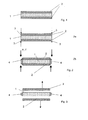
- Fig. 1 is a preferred membrane electrode unit in a Intermediate step of the method according to the invention shown.
- a layer arrangement 1 is on both sides with a polymer material 2 covered.
- the method according to claim 1 is explained in Fig. 2 a, 2 b and Fig. 3.
- the general production of the layer arrangement 1 can be, for example the unpublished patent application DE 10052224.6 or the likewise not previously published patent application DE 10124272.7 be taken.
- a preferred Membrane electrode unit itself comprises at least one gas diffusion layer, at least one carbon base layer, at least a catalyst layer and at least one polymer electrolyte membrane-containing Layer.
- the general Structure of the non-prepublished patent application DE 10052224.6 are taken.
- Other MEA compositions are however equally possible.
- the layer arrangement produced in this way preferably not only the layer arrangement 1 but also the polymer material 2 in film form is processed as a roll product, wherein both webs preferably have the same width.
- a respective plastic film web 2 is continuously fed above and below the still uncut layer arrangement web 1.
- the polymer material is applied in the form of films on the top and bottom of the layer assembly.
- This composite is punched out with appropriately heated and shaped punching tools.
- the punching blades whose cutting edge corresponds to each constructivestanzenden profile, heated in one embodiment by means of a heater, wherein conveniently the temperature of the blade with the aid of an electric regulator is infinitely variable.
- the composite of several layers of material along the cutting edge of the punching knife is circumferentially welded.
- the composite of layer arrangement and polymer material to be processed can also be heated.
- a punching tool here is the patent application DE 195 21 359 called.
- the composite material applied to the cutting edge is circumferentially welded along the cutting edge of the punching knife by the high-frequency field generated at the cutting edges of the punching blade, ie the individual layers of the composite are connected to one another at their outermost edges.
- the knife is additionally heated.
- the disclosure document DE 1 510 044 may be mentioned for this embodiment.
- the plying of the layers taking place during stamping takes place at their outermost edges and thus connects the MEA layer and the film layers above and below each other at their outermost edge.
- the punching out and simultaneous fixing of the film 2 described at least in part at the outermost edge of the layer arrangement 1 has the advantage that the time required for punching and welding can be significantly reduced, thus allowing high quantities and short cycle times, and secondly this procedure leads to a qualitatively more uniform product.
- thermoplastic Film material 2 Since the polymer material used for sealing 2 in contrast cheaper for the commonly used silicone material, also incurred lower gasket material costs and the Waste is 100% recyclable.
- the advantage of the preferred thermoplastic Film material 2 compared to other materials, which still have to be cured or crosslinked is his easy handling associated with a protective effect on the layer arrangement 1 through the not yet removed Protective film 2, against dust and / or mechanical damage during storage or before further processing.
- the next step comprises a membrane electrode unit, the one layer arrangement 1 of an anode electrode, a cathode electrode and disposed therebetween Membrane in which the edge zones 4 or edge regions of the Layer arrangement 1 by a there applied and in the Edge zones 4 penetrated polymer material 2 against the environment and the working gases are sealed.
- Fig. 2 b as a possible embodiment is indicated, with the protective cover provided layer arrangement 1 in a not shown Press inserted.
- the sheet-coated layer arrangement 1 softens or The polymer material 2 located in the edge zone 4 melts and penetrates the edge zones 4 of the layer arrangement 1.
- the so melted or softened material penetrates on both sides through the porous layer to the polymer electrolyte membrane. This process is also called saturation.
- saturation Within of seconds, so the edge area in the circumference of the layer arrangement sealed gas-tight. The no longer needed or unheated foil 2 inside the sealed margins 4 is removed, e.g. aspirated, as in Fig. 3 by way of example shown.
- the MEA and polymer material webs to be processed as a roll product can also have a mutually different width.
- the polymer material protrudes at the edges facing the running direction.
- This difference in width of the plastic film web can be a few mm to a few cm.
- the film web may have a punched profile at its edges in the running direction.
- the punching and simultaneous fixing of the layer assembly with the polymer material takes place along the cutting edge of the punching iron, wherein the two opposite, not protruding, but flush with each other edges of the film-coated MEA, which are arranged transversely to the direction, attached to each other at the outermost edge of the layer assembly or connected, preferably welded together.
- the projecting edges of the plastic film web which were located in the running direction of the webs, are fastened or connected to one another at the outermost end of their cutting edge, preferably welded.
- the MEA flush-fitting edge zones of the layer arrangement are penetrated by the polymer material, wherein the edge zones of the layer arrangement with the projecting film edges in the periphery of their projecting film edges are welded together, wherein the edges of the layer assembly, which are not flush with the film web, as well, are penetrated at its outermost edge of the polymer material.
- selective reinforcements can be applied within the MEA.
- the membrane electrode unit previously prepared according to process step a is cut or punched to the required size. Subsequently, this layer arrangement is overlaid and underlaid with polymer material in film form, the film projecting on all sides of the MEA. This film projection can be a few mm to a few cm.
- the film supernatant is then bonded together by heating and pressing, also penetrating the outermost edges of the layer assembly with the softened or molten polymeric material.
- selective reinforcements can be applied within the MEA.
- the protruding edge of the film is used as a seal when installed between the bipolar plates of a fuel cell.
- this supernatant can be used alone or in conjunction with conventional sealing technology as a seal. Again, the portion of the unneeded or unheated foil is removed from the surfaces of the layer assembly before the MEA so produced is incorporated into a fuel cell.
- sealing materials are not without problems.
- the material must be next to the required Sealing properties, such as Gas and water vapor barrier properties, dry or moist working gases such as e.g. Oxygen, hydrogen at elevated temperature (about 120 ° C) in Resist continuous load, without aging of the sealing material by embrittlement or degradation or even one Swelling occurs, i.
- the material must also be resistant to hydrolysis his.
- the use of materials with additives such as. Plasticizers cause over time that they diffuse out of the material and otherwise deposit or poison the catalyst, causing premature failure of the system.
- the sealing material is preferably thermoplastic.
- a thermoplastic Polymer are only suitable for those who specific requirements in a hydrogen / oxygen fuel cell in terms of mechanical and chemical Requirements suffice. Furthermore, it is required that the thermoplastic Material, while retaining all the aforementioned properties, remains stable until at least 120 ° C.
- the polymer material contains as base material polyethylene or polyethylene-containing Material, polypropylene or polypropylene-containing material, Polyester or polyester-containing material, polyamide or polyamide-containing material, ethylene-vinyl alcohol or ethylene vinyl alcohol-containing Material, polyvinylidene chloride or polyvinylidene chloride-containing Material, polyvinyl chloride or polyvinyl chloride-containing Material individually or in combination and / or graft and / or copolymers or consists thereof. It However, it is also possible to modify the polymer material so that certain for processing (e.g., sealability) or the operation in a fuel cell necessary physical and / or chemical properties are realized can.
- certain for processing e.g., sealability
- the operation in a fuel cell necessary physical and / or chemical properties are realized can.
Landscapes
- Life Sciences & Earth Sciences (AREA)
- Engineering & Computer Science (AREA)
- Manufacturing & Machinery (AREA)
- Sustainable Development (AREA)
- Sustainable Energy (AREA)
- Chemical & Material Sciences (AREA)
- Chemical Kinetics & Catalysis (AREA)
- Electrochemistry (AREA)
- General Chemical & Material Sciences (AREA)
- Fuel Cell (AREA)
- Lining Or Joining Of Plastics Or The Like (AREA)
- Sealing Using Fluids, Sealing Without Contact, And Removal Of Oil (AREA)
- Seal Device For Vehicle (AREA)
- Sealing Devices (AREA)
Applications Claiming Priority (2)
| Application Number | Priority Date | Filing Date | Title |
|---|---|---|---|
| DE10140684 | 2001-08-24 | ||
| DE10140684A DE10140684A1 (de) | 2001-08-24 | 2001-08-24 | Dichtungsaufbau für eine MEA und Verfahren zur Herstellung des Dichtungsaufbaus |
Publications (3)
| Publication Number | Publication Date |
|---|---|
| EP1289037A2 true EP1289037A2 (fr) | 2003-03-05 |
| EP1289037A3 EP1289037A3 (fr) | 2004-06-16 |
| EP1289037B1 EP1289037B1 (fr) | 2007-08-01 |
Family
ID=7695962
Family Applications (1)
| Application Number | Title | Priority Date | Filing Date |
|---|---|---|---|
| EP02017267A Expired - Lifetime EP1289037B1 (fr) | 2001-08-24 | 2002-08-01 | Assemblage d'étanchéité pour un MEA et méthode de fabrication de l' assemblage d'étanchéité |
Country Status (6)
| Country | Link |
|---|---|
| US (1) | US6921599B2 (fr) |
| EP (1) | EP1289037B1 (fr) |
| JP (1) | JP2003077491A (fr) |
| AT (1) | ATE368946T1 (fr) |
| CA (1) | CA2399340A1 (fr) |
| DE (2) | DE10140684A1 (fr) |
Cited By (1)
| Publication number | Priority date | Publication date | Assignee | Title |
|---|---|---|---|---|
| WO2009068551A1 (fr) * | 2007-11-28 | 2009-06-04 | Basf Se | Séchage continu/membrane speek |
Families Citing this family (29)
| Publication number | Priority date | Publication date | Assignee | Title |
|---|---|---|---|---|
| DE10315796B4 (de) * | 2003-04-07 | 2009-06-04 | Umicore Ag & Co. Kg | Schichtenaufbau für eine elektrochemische Zelle, Verfahren zu seiner Herstellung und Verwendung desselben |
| US20050014056A1 (en) | 2003-07-14 | 2005-01-20 | Umicore Ag & Co. Kg | Membrane electrode unit for electrochemical equipment |
| EP1654776B1 (fr) * | 2003-07-14 | 2013-09-11 | Umicore AG & Co. KG | Unité membrane-électrode pour des installation électrochmiques |
| JP4709518B2 (ja) * | 2004-09-29 | 2011-06-22 | 株式会社東芝 | プロトン伝導膜及び燃料電池 |
| JP4746309B2 (ja) * | 2004-11-30 | 2011-08-10 | 株式会社東芝 | 燃料電池 |
| US20080050639A1 (en) * | 2006-08-23 | 2008-02-28 | Michael Medina | Bipolar flow field plate assembly and method of making the same |
| US8221930B2 (en) * | 2006-08-23 | 2012-07-17 | Daimler Ag | Bipolar separators with improved fluid distribution |
| TW200820478A (en) * | 2006-10-18 | 2008-05-01 | Antig Technology Corp | Fuel cell structure |
| US20090004543A1 (en) * | 2007-06-27 | 2009-01-01 | Seungsoo Jung | Membrane electrode assemblies for fuel cells and methods of making |
| GB0718620D0 (en) | 2007-09-25 | 2007-10-31 | Johnson Matthey Plc | Membrane electrode assembly |
| JP4444355B2 (ja) * | 2008-09-03 | 2010-03-31 | 株式会社東芝 | 燃料電池 |
| WO2019136272A1 (fr) | 2018-01-04 | 2019-07-11 | University Of Washington | Membranes céramiques sol-gel sélectives nanoporeuses, structures à membrane sélective, et procédés associés |
| SE546221C2 (en) * | 2020-04-07 | 2024-07-16 | Powercell Sweden Ab | Manufacturing arrangement and method for a fuel cell stack |
| DE102020213123A1 (de) | 2020-10-19 | 2022-04-21 | Robert Bosch Gesellschaft mit beschränkter Haftung | Membran-Elektroden-Einheit für eine elektrochemische Zelle und Verfahren zur Herstellung einer Membran-Elektroden-Einheit |
| DE102020213126A1 (de) | 2020-10-19 | 2022-04-21 | Robert Bosch Gesellschaft mit beschränkter Haftung | Membran-Elektroden-Einheit für eine elektrochemische Zelle und Verfahren zur Herstellung einer Membran-Elektroden-Einheit |
| DE102020213140A1 (de) | 2020-10-19 | 2022-04-21 | Robert Bosch Gesellschaft mit beschränkter Haftung | Membran-Elektroden-Einheit für eine elektrochemische Zelle und Verfahren zur Herstellung einer Membran-Elektroden-Einheit |
| DE102020213132A1 (de) | 2020-10-19 | 2022-04-21 | Robert Bosch Gesellschaft mit beschränkter Haftung | Membran-Elektroden-Einheit für eine elektrochemische Zelle und Verfahren zur Herstellung einer Membran-Elektroden-Einheit |
| DE102020216001A1 (de) | 2020-12-16 | 2022-06-23 | Robert Bosch Gesellschaft mit beschränkter Haftung | Zwischenlage für eine Brennstoffzelle, System mit einer Zwischenlage und einer Membran-Elektroden-Einheit und Brennstoffzelle |
| DE102020216093A1 (de) | 2020-12-17 | 2022-06-23 | Robert Bosch Gesellschaft mit beschränkter Haftung | Membran-Elektroden-Einheit für eine elektrochemische Zelle und Verfahren zur Herstellung einer Membran-Elektroden-Einheit |
| DE102021205008A1 (de) | 2021-05-18 | 2022-11-24 | Robert Bosch Gesellschaft mit beschränkter Haftung | Elektrochemische Zelle und Verfahren zur Herstellung einer elektrochemischen Zelle |
| DE102021205857A1 (de) | 2021-06-10 | 2022-12-15 | Robert Bosch Gesellschaft mit beschränkter Haftung | Membran-Elektroden-Anordnung und Verfahren zum Herstellen einer Membran und einer Elektrodenschicht für eine Membran-Elektroden-Anordnung |
| DE102021210509A1 (de) | 2021-09-22 | 2023-03-23 | Robert Bosch Gesellschaft mit beschränkter Haftung | Membran-Elektroden-Einheit für eine elektrochemische Zelle und Verfahren zum Herstellen einer elektrochemischen Zelle |
| DE102021211884A1 (de) | 2021-10-21 | 2023-04-27 | Robert Bosch Gesellschaft mit beschränkter Haftung | Membran-Elektroden-Einheit für eine elektrochemische Zelle und Verfahren zum Herstellen einer Membran-Elektroden-Einheit |
| DE102021212400A1 (de) | 2021-11-03 | 2023-05-04 | Robert Bosch Gesellschaft mit beschränkter Haftung | Elektrochemische Zelle mit einer Membran-Elektroden-Einheit, einer Diffusionslage und einer Verteilerplatte, und Verfahren zum Herstellen einer elektrochemischen Zelle |
| DE102021212398A1 (de) | 2021-11-03 | 2023-05-04 | Robert Bosch Gesellschaft mit beschränkter Haftung | Membran-Elektroden-Einheit für eine elektrochemische Zelle |
| DE102021212401A1 (de) | 2021-11-03 | 2023-05-04 | Robert Bosch Gesellschaft mit beschränkter Haftung | Membran-Elektroden-Einheit für eine elektrochemische Zelle und Verfahren zum Herstellen einer Membran-Elektroden-Einheit |
| DE102021214662A1 (de) | 2021-12-20 | 2023-06-22 | Robert Bosch Gesellschaft mit beschränkter Haftung | Membran und Membran-Elektroden-Anordnung sowie Verfahren zu deren Herstellung sowie eine elektrochemische Zelle |
| DE102022209862A1 (de) | 2022-09-20 | 2024-03-21 | Robert Bosch Gesellschaft mit beschränkter Haftung | Membran-Elektroden-Anordnung für eine elektrochemische Zelle und Verfahren zum Herstellen einer Membran-Elektroden-Anordnung |
| DE102023211051A1 (de) | 2023-11-08 | 2025-05-08 | Robert Bosch Gesellschaft mit beschränkter Haftung | Verfahren zur Herstellung einer Membran-Elektroden-Einheit für eine elektrochemische Zelle |
Family Cites Families (19)
| Publication number | Priority date | Publication date | Assignee | Title |
|---|---|---|---|---|
| DE1510044A1 (de) * | 1964-09-01 | 1969-05-22 | United Shoe Machinery Corp | Maschine zum Stanzen und/oder Schweissen,beispielsweise von Schuhteilen |
| US3522095A (en) * | 1965-01-14 | 1970-07-28 | Gen Electric | Laminar membrane fuel cells and processes for their manufacture |
| NL6511877A (fr) | 1965-09-11 | 1967-03-13 | ||
| FR2564249B1 (fr) | 1984-05-11 | 1986-09-12 | Alsthom Atlantique | Amenagements aux structures des piles a combustible |
| US4652502A (en) * | 1985-12-30 | 1987-03-24 | International Fuel Cells, Inc. | Porous plate for an electrochemical cell and method for making the porous plate |
| DE19521359A1 (de) | 1995-06-12 | 1996-12-19 | Kiefel Gmbh Paul | Stanzwerkzeug |
| US5945192A (en) * | 1995-06-29 | 1999-08-31 | Japan Gore-Tex, Inc. | Sealing assembly for a solid polymer ion exchange membrane |
| DE19542475C2 (de) | 1995-11-15 | 1999-10-28 | Ballard Power Systems | Polymerelektrolytmembran-Brennstoffzelle sowie Verfahren zur Herstellung einer Verteilerplatte für eine solche Zelle |
| DE19548422A1 (de) * | 1995-12-22 | 1997-09-11 | Hoechst Ag | Materialverbunde und ihre kontinuierliche Herstellung |
| DE19703214C2 (de) | 1997-01-29 | 2003-10-30 | Proton Motor Fuel Cell Gmbh | Membran-Elektrodeneinheit mit integriertem Dichtrand und Verfahren zu ihrer Herstellung |
| JPH1145729A (ja) * | 1997-07-25 | 1999-02-16 | Fuji Electric Co Ltd | 固体高分子電解質型燃料電池 |
| US5910378A (en) * | 1997-10-10 | 1999-06-08 | Minnesota Mining And Manufacturing Company | Membrane electrode assemblies |
| DE29811922U1 (de) | 1998-07-04 | 1999-01-07 | H2-Interpower GmbH, 91126 Schwabach | Brennstoffzelle sowie Brennstoffzellenanordnung |
| US6165634A (en) * | 1998-10-21 | 2000-12-26 | International Fuel Cells Llc | Fuel cell with improved sealing between individual membrane assemblies and plate assemblies |
| US6159628A (en) * | 1998-10-21 | 2000-12-12 | International Fuel Cells Llc | Use of thermoplastic films to create seals and bond PEM cell components |
| JP4066117B2 (ja) | 1999-06-11 | 2008-03-26 | Nok株式会社 | 燃料電池用ガスケット |
| JP2001118592A (ja) * | 1999-10-18 | 2001-04-27 | Matsushita Electric Ind Co Ltd | 高分子電解質型燃料電池及び電池スタック |
| DE10052224B4 (de) | 2000-10-21 | 2009-12-10 | Daimler Ag | Gasdiffusionselektrode mit erhöhter Toleranz gegenüber Feuchteschwankung, eine diese aufweisende Membranelektrodenanordnung, Verfahren zur Herstellung der Gasdiffusionselektrode und der Membranelektrodenanordnung sowie Verwendung der Membranelektrodenanordnung |
| DE10124272A1 (de) | 2001-05-18 | 2002-11-21 | Daimler Chrysler Ag | Verfahren zur kontinuierlichen Herstellung einer Polymerelektrolytmembran-Elektrodenanordnung |
-
2001
- 2001-08-24 DE DE10140684A patent/DE10140684A1/de not_active Ceased
-
2002
- 2002-08-01 AT AT02017267T patent/ATE368946T1/de not_active IP Right Cessation
- 2002-08-01 DE DE50210585T patent/DE50210585D1/de not_active Expired - Lifetime
- 2002-08-01 EP EP02017267A patent/EP1289037B1/fr not_active Expired - Lifetime
- 2002-08-20 US US10/223,797 patent/US6921599B2/en not_active Expired - Fee Related
- 2002-08-22 CA CA002399340A patent/CA2399340A1/fr not_active Abandoned
- 2002-08-23 JP JP2002244305A patent/JP2003077491A/ja not_active Abandoned
Cited By (1)
| Publication number | Priority date | Publication date | Assignee | Title |
|---|---|---|---|---|
| WO2009068551A1 (fr) * | 2007-11-28 | 2009-06-04 | Basf Se | Séchage continu/membrane speek |
Also Published As
| Publication number | Publication date |
|---|---|
| US20030049367A1 (en) | 2003-03-13 |
| EP1289037B1 (fr) | 2007-08-01 |
| US6921599B2 (en) | 2005-07-26 |
| CA2399340A1 (fr) | 2003-02-24 |
| JP2003077491A (ja) | 2003-03-14 |
| DE50210585D1 (de) | 2007-09-13 |
| ATE368946T1 (de) | 2007-08-15 |
| DE10140684A1 (de) | 2003-03-06 |
| EP1289037A3 (fr) | 2004-06-16 |
Similar Documents
| Publication | Publication Date | Title |
|---|---|---|
| EP1289037B1 (fr) | Assemblage d'étanchéité pour un MEA et méthode de fabrication de l' assemblage d'étanchéité | |
| DE19703214C2 (de) | Membran-Elektrodeneinheit mit integriertem Dichtrand und Verfahren zu ihrer Herstellung | |
| EP1320142B1 (fr) | Structure d'étanchéité pour piles à combustible | |
| DE102015010440B4 (de) | Verfahren und Vorrichtung zum Herstellen einer Membran-Elektroden-Anordnung für eine Brennstoffzelle | |
| DE60203392T2 (de) | Membranelektrodenbaugruppe für polymerische membranbrennstoffzellen | |
| DE112014001881B4 (de) | Wassertransferverbund, Befeuchtermodul und Befeuchter | |
| DE102011105072B3 (de) | Haltevorrichtung mit einer Membran einer Membran-Elektroden-Einheit für eine Brennstoffzelle und Verfahren zu deren Herstellung | |
| WO1998033225A9 (fr) | Unite d'electrodes-membranes a collerette d'etancheite integree, et procede de fabrication | |
| DE10207743A1 (de) | Elektrode für eine Polymerelektrolyt-Brennstoffzelle, Trennwand hierfür sowie Polymerelektrolyt-Brennstoffzelle und Elektrizitätserzeugungssystem unter Verwendung derselben | |
| EP2002499A1 (fr) | Procédé de fabrication d'une unité d'électrode membranaire pour pile à combustible | |
| EP4248510A1 (fr) | Procédé de fabrication d'un ensemble membrane-électrode et ensemble membrane-électrode pour une pile à combustible | |
| DE102012218303A1 (de) | Verfahren zur Herstellung einer Befeuchtungseinrichtung zur Befeuchtung von Prozessgasen sowie Befeuchtungseinrichtung | |
| EP1653538A1 (fr) | Module de plaque de refroidissement avec une etancheite integrée pour une pile à combustible | |
| DE102015100737B4 (de) | Elektrochemische Einheit für eine elektrochemische Vorrichtung und Verfahren zum Herstellen einer solchen | |
| DE102017000960B4 (de) | Verfahren zum Herstellen einer Membran-Elektroden-Anordnung für eine Brennstoffzelle | |
| DE2803033C2 (fr) | ||
| DE102021105017A1 (de) | Elektrochemische Einheit für eine elektrochemische Vorrichtung und Verfahren zum Herstellen einer elektrochemischen Einheit für eine elektrochemische Vorrichtung | |
| DE112004001748B4 (de) | Brennstoffzellenanordnung und Verfahren zur Herstellung | |
| DE102016000937A1 (de) | Verfahren und Vorrichtung zum Herstellen einer Membran-Elektroden-Anordnung für eine Brennstoffzelle | |
| DE102021105029A1 (de) | Elektrochemische Einheit für eine elektrochemische Vorrichtung und Verfahren zum Herstellen einer elektrochemischen Einheit für eine elektrochemische Vorrichtung | |
| DE102016224611B4 (de) | Brennstoffzellenaufbau und Verfahren zu dessen Herstellung | |
| EP4320657B1 (fr) | Pile à combustible à couches d'élastomère et procédé de fabrication de pile à combustible | |
| WO2024133022A1 (fr) | Procédé de fabrication d'un assemblage membrane-électrodes multicouche, en particulier à cinq ou six couches | |
| DE102024116016A1 (de) | Feuchtigkeitsdurchlässige Membran, Befeuchtermodul, Verfahren zur Herstellung eines Befeuchtermoduls sowie Befeuchter für ein Brennstoffzellensystem | |
| DE102020201365A1 (de) | Verfahren zur Herstellung einer Brennstoffzelle, Brennstoffzelle |
Legal Events
| Date | Code | Title | Description |
|---|---|---|---|
| PUAI | Public reference made under article 153(3) epc to a published international application that has entered the european phase |
Free format text: ORIGINAL CODE: 0009012 |
|
| AK | Designated contracting states |
Kind code of ref document: A2 Designated state(s): AT BE BG CH CY CZ DE DK EE ES FI FR GB GR IE IT LI LU MC NL PT SE SK TR |
|
| AX | Request for extension of the european patent |
Extension state: AL LT LV MK RO SI |
|
| PUAL | Search report despatched |
Free format text: ORIGINAL CODE: 0009013 |
|
| AK | Designated contracting states |
Kind code of ref document: A3 Designated state(s): AT BE BG CH CY CZ DE DK EE ES FI FR GB GR IE IT LI LU MC NL PT SE SK TR |
|
| AX | Request for extension of the european patent |
Extension state: AL LT LV MK RO SI |
|
| RIC1 | Information provided on ipc code assigned before grant |
Ipc: 7H 01M 8/02 B Ipc: 7H 01M 8/10 A |
|
| 17P | Request for examination filed |
Effective date: 20040730 |
|
| 17Q | First examination report despatched |
Effective date: 20041103 |
|
| AKX | Designation fees paid |
Designated state(s): AT BE BG CH CY CZ DE DK EE ES FI FR GB GR IE IT LI LU MC NL PT SE SK TR |
|
| 17Q | First examination report despatched |
Effective date: 20041103 |
|
| GRAP | Despatch of communication of intention to grant a patent |
Free format text: ORIGINAL CODE: EPIDOSNIGR1 |
|
| RAP1 | Party data changed (applicant data changed or rights of an application transferred) |
Owner name: DAIMLERCHRYSLER AG |
|
| GRAS | Grant fee paid |
Free format text: ORIGINAL CODE: EPIDOSNIGR3 |
|
| GRAA | (expected) grant |
Free format text: ORIGINAL CODE: 0009210 |
|
| AK | Designated contracting states |
Kind code of ref document: B1 Designated state(s): AT BE BG CH CY CZ DE DK EE ES FI FR GB GR IE IT LI LU MC NL PT SE SK TR |
|
| REG | Reference to a national code |
Ref country code: GB Ref legal event code: FG4D Free format text: NOT ENGLISH |
|
| REG | Reference to a national code |
Ref country code: CH Ref legal event code: EP |
|
| REG | Reference to a national code |
Ref country code: IE Ref legal event code: FG4D Free format text: LANGUAGE OF EP DOCUMENT: GERMAN |
|
| REF | Corresponds to: |
Ref document number: 50210585 Country of ref document: DE Date of ref document: 20070913 Kind code of ref document: P |
|
| RAP2 | Party data changed (patent owner data changed or rights of a patent transferred) |
Owner name: DAIMLER AG |
|
| PG25 | Lapsed in a contracting state [announced via postgrant information from national office to epo] |
Ref country code: ES Free format text: LAPSE BECAUSE OF FAILURE TO SUBMIT A TRANSLATION OF THE DESCRIPTION OR TO PAY THE FEE WITHIN THE PRESCRIBED TIME-LIMIT Effective date: 20071112 Ref country code: BG Free format text: LAPSE BECAUSE OF FAILURE TO SUBMIT A TRANSLATION OF THE DESCRIPTION OR TO PAY THE FEE WITHIN THE PRESCRIBED TIME-LIMIT Effective date: 20071101 Ref country code: FI Free format text: LAPSE BECAUSE OF FAILURE TO SUBMIT A TRANSLATION OF THE DESCRIPTION OR TO PAY THE FEE WITHIN THE PRESCRIBED TIME-LIMIT Effective date: 20070801 Ref country code: NL Free format text: LAPSE BECAUSE OF FAILURE TO SUBMIT A TRANSLATION OF THE DESCRIPTION OR TO PAY THE FEE WITHIN THE PRESCRIBED TIME-LIMIT Effective date: 20070801 |
|
| NLV1 | Nl: lapsed or annulled due to failure to fulfill the requirements of art. 29p and 29m of the patents act | ||
| GBV | Gb: ep patent (uk) treated as always having been void in accordance with gb section 77(7)/1977 [no translation filed] |
Effective date: 20070801 |
|
| BERE | Be: lapsed |
Owner name: DAIMLERCHRYSLER A.G. Effective date: 20070831 |
|
| REG | Reference to a national code |
Ref country code: IE Ref legal event code: FD4D |
|
| EN | Fr: translation not filed | ||
| REG | Reference to a national code |
Ref country code: CH Ref legal event code: PL |
|
| PG25 | Lapsed in a contracting state [announced via postgrant information from national office to epo] |
Ref country code: LI Free format text: LAPSE BECAUSE OF NON-PAYMENT OF DUE FEES Effective date: 20070831 Ref country code: MC Free format text: LAPSE BECAUSE OF NON-PAYMENT OF DUE FEES Effective date: 20070831 Ref country code: CH Free format text: LAPSE BECAUSE OF NON-PAYMENT OF DUE FEES Effective date: 20070831 Ref country code: DK Free format text: LAPSE BECAUSE OF FAILURE TO SUBMIT A TRANSLATION OF THE DESCRIPTION OR TO PAY THE FEE WITHIN THE PRESCRIBED TIME-LIMIT Effective date: 20070801 Ref country code: GR Free format text: LAPSE BECAUSE OF FAILURE TO SUBMIT A TRANSLATION OF THE DESCRIPTION OR TO PAY THE FEE WITHIN THE PRESCRIBED TIME-LIMIT Effective date: 20071102 |
|
| PG25 | Lapsed in a contracting state [announced via postgrant information from national office to epo] |
Ref country code: SK Free format text: LAPSE BECAUSE OF FAILURE TO SUBMIT A TRANSLATION OF THE DESCRIPTION OR TO PAY THE FEE WITHIN THE PRESCRIBED TIME-LIMIT Effective date: 20070801 Ref country code: GB Free format text: LAPSE BECAUSE OF FAILURE TO SUBMIT A TRANSLATION OF THE DESCRIPTION OR TO PAY THE FEE WITHIN THE PRESCRIBED TIME-LIMIT Effective date: 20070801 Ref country code: IE Free format text: LAPSE BECAUSE OF FAILURE TO SUBMIT A TRANSLATION OF THE DESCRIPTION OR TO PAY THE FEE WITHIN THE PRESCRIBED TIME-LIMIT Effective date: 20070801 Ref country code: PT Free format text: LAPSE BECAUSE OF FAILURE TO SUBMIT A TRANSLATION OF THE DESCRIPTION OR TO PAY THE FEE WITHIN THE PRESCRIBED TIME-LIMIT Effective date: 20080102 Ref country code: CZ Free format text: LAPSE BECAUSE OF FAILURE TO SUBMIT A TRANSLATION OF THE DESCRIPTION OR TO PAY THE FEE WITHIN THE PRESCRIBED TIME-LIMIT Effective date: 20070801 |
|
| PLBE | No opposition filed within time limit |
Free format text: ORIGINAL CODE: 0009261 |
|
| STAA | Information on the status of an ep patent application or granted ep patent |
Free format text: STATUS: NO OPPOSITION FILED WITHIN TIME LIMIT |
|
| PG25 | Lapsed in a contracting state [announced via postgrant information from national office to epo] |
Ref country code: SE Free format text: LAPSE BECAUSE OF FAILURE TO SUBMIT A TRANSLATION OF THE DESCRIPTION OR TO PAY THE FEE WITHIN THE PRESCRIBED TIME-LIMIT Effective date: 20071101 |
|
| 26N | No opposition filed |
Effective date: 20080506 |
|
| PG25 | Lapsed in a contracting state [announced via postgrant information from national office to epo] |
Ref country code: FR Free format text: LAPSE BECAUSE OF FAILURE TO SUBMIT A TRANSLATION OF THE DESCRIPTION OR TO PAY THE FEE WITHIN THE PRESCRIBED TIME-LIMIT Effective date: 20080328 |
|
| PG25 | Lapsed in a contracting state [announced via postgrant information from national office to epo] |
Ref country code: BE Free format text: LAPSE BECAUSE OF NON-PAYMENT OF DUE FEES Effective date: 20070831 |
|
| PG25 | Lapsed in a contracting state [announced via postgrant information from national office to epo] |
Ref country code: AT Free format text: LAPSE BECAUSE OF NON-PAYMENT OF DUE FEES Effective date: 20070801 |
|
| PG25 | Lapsed in a contracting state [announced via postgrant information from national office to epo] |
Ref country code: EE Free format text: LAPSE BECAUSE OF FAILURE TO SUBMIT A TRANSLATION OF THE DESCRIPTION OR TO PAY THE FEE WITHIN THE PRESCRIBED TIME-LIMIT Effective date: 20070801 |
|
| PG25 | Lapsed in a contracting state [announced via postgrant information from national office to epo] |
Ref country code: CY Free format text: LAPSE BECAUSE OF FAILURE TO SUBMIT A TRANSLATION OF THE DESCRIPTION OR TO PAY THE FEE WITHIN THE PRESCRIBED TIME-LIMIT Effective date: 20070801 |
|
| PG25 | Lapsed in a contracting state [announced via postgrant information from national office to epo] |
Ref country code: LU Free format text: LAPSE BECAUSE OF NON-PAYMENT OF DUE FEES Effective date: 20070801 |
|
| PG25 | Lapsed in a contracting state [announced via postgrant information from national office to epo] |
Ref country code: TR Free format text: LAPSE BECAUSE OF FAILURE TO SUBMIT A TRANSLATION OF THE DESCRIPTION OR TO PAY THE FEE WITHIN THE PRESCRIBED TIME-LIMIT Effective date: 20070801 |
|
| PG25 | Lapsed in a contracting state [announced via postgrant information from national office to epo] |
Ref country code: IT Free format text: LAPSE BECAUSE OF NON-PAYMENT OF DUE FEES Effective date: 20070831 |
|
| PGFP | Annual fee paid to national office [announced via postgrant information from national office to epo] |
Ref country code: DE Payment date: 20151029 Year of fee payment: 14 |
|
| REG | Reference to a national code |
Ref country code: DE Ref legal event code: R119 Ref document number: 50210585 Country of ref document: DE |
|
| PG25 | Lapsed in a contracting state [announced via postgrant information from national office to epo] |
Ref country code: DE Free format text: LAPSE BECAUSE OF NON-PAYMENT OF DUE FEES Effective date: 20170301 |