EP1289064A2 - Elektrischer Vebinder mit ionomerem Isolationsmaterial - Google Patents
Elektrischer Vebinder mit ionomerem Isolationsmaterial Download PDFInfo
- Publication number
- EP1289064A2 EP1289064A2 EP02018514A EP02018514A EP1289064A2 EP 1289064 A2 EP1289064 A2 EP 1289064A2 EP 02018514 A EP02018514 A EP 02018514A EP 02018514 A EP02018514 A EP 02018514A EP 1289064 A2 EP1289064 A2 EP 1289064A2
- Authority
- EP
- European Patent Office
- Prior art keywords
- sleeve
- heat
- crimp barrel
- shrinkable
- crimp
- Prior art date
- Legal status (The legal status is an assumption and is not a legal conclusion. Google has not performed a legal analysis and makes no representation as to the accuracy of the status listed.)
- Granted
Links
Images


Classifications
-
- H—ELECTRICITY
- H01—ELECTRIC ELEMENTS
- H01R—ELECTRICALLY-CONDUCTIVE CONNECTIONS; STRUCTURAL ASSOCIATIONS OF A PLURALITY OF MUTUALLY-INSULATED ELECTRICAL CONNECTING ELEMENTS; COUPLING DEVICES; CURRENT COLLECTORS
- H01R4/00—Electrically-conductive connections between two or more conductive members in direct contact, i.e. touching one another; Means for effecting or maintaining such contact; Electrically-conductive connections having two or more spaced connecting locations for conductors and using contact members penetrating insulation
- H01R4/70—Insulation of connections
- H01R4/72—Insulation of connections using a heat shrinking insulating sleeve
- H01R4/726—Making a non-soldered electrical connection simultaneously with the heat shrinking
-
- H—ELECTRICITY
- H01—ELECTRIC ELEMENTS
- H01R—ELECTRICALLY-CONDUCTIVE CONNECTIONS; STRUCTURAL ASSOCIATIONS OF A PLURALITY OF MUTUALLY-INSULATED ELECTRICAL CONNECTING ELEMENTS; COUPLING DEVICES; CURRENT COLLECTORS
- H01R11/00—Individual connecting elements providing two or more spaced connecting locations for conductive members which are, or may be, thereby interconnected, e.g. end pieces for wires or cables supported by the wire or cable and having means for facilitating electrical connection to some other wire, terminal, or conductive member, blocks of binding posts
- H01R11/11—End pieces or tapping pieces for wires, supported by the wire and for facilitating electrical connection to some other wire, terminal or conductive member
- H01R11/12—End pieces terminating in an eye, hook, or fork
Definitions
- a typical crimp connector is described in U.S. patent No. 4,151,364 (Ellis), issued on April 24, 1979.
- the crimp connector described in this patent comprises an insulating sleeve having a metal crimp barrel permanently positioned therein.
- This type of crimp connector is manufactured by inserting the crimp barrel into a heat-shrinkable sleeve in its expanded state and then partially shrinking the sleeve down onto the crimp barrel to permanently retain the crimp barrel in the sleeve. Since the sleeve and the crimp barrel are permanently attached, the crimping force must be applied to the crimp barrel through the heat-shrinkable sleeve.
- ionomers are known to possess a number of other properties which are desirable in heat-shrinkable sleeves for crimp connectors, and which render them equally or more suitable to this application than polyamides.
- ionomers are known to possess a high degree of transparency; they accept colorants which do not materially deteriorate transparency, allowing for excellent color coding of products; they are typically less expensive than nylon; and can be made with varying degrees of stiffness.
- Another important advantage of ionomers is that they are heat-shrinkable at significantly lower temperatures than polyamide connector sleeves, typically about 50°C lower.
- the lower heat shrink temperature renders ionomers more compatible with commonly used heat activated adhesives, such as ethylene-vinyl acetate- (EVA)-based hot melt adhesives, and lessens the likelihood of insufficient heating of the sleeve during heat shrinking and of deterioration of the wire coating due to excessive heating.
- EVA ethylene-vinyl acetate-
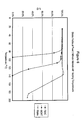
- Figure 6 is a graph which compares the degree of shrinkage against temperature for ionomer tubing, polyolefin tubing and polyamide tubing.
- FIG. 1 illustrates a crimp connector 10 according to a first preferred embodiment of the present invention.
- Connector 10 is of the type commonly referred to as a "butt" connector since it is used to form an electrically conductive butt joint between the ends of two electrical conductors.
- the butt connector 10 shown in Figure 1 comprises a tubular metallic crimp barrel 12, and a heat-shrinkable polymeric sleeve 14.
- the heat-shrinkable sleeve 14 is also of a generally cylindrical shape, having an outer surface 26, an inner surface 28 and first and second open ends 30 and 32.
- the inner surface 28 defines a hollow interior 34 of the sleeve 14 extending between its open ends 30 and 32.
- the heat-shrinkable insulating sleeve according to the invention preferably has an adhesive layer 42 formed on the inner surface 28 thereof, with the adhesive layer preferably being formed inside sleeve 14 by melt co-extrusion.
- the adhesive resin composition is preferably a conventional hot-melt adhesive composition which melts and flows at temperatures required for heat shrinking of the sleeve.
- hot-melt adhesives which can be employed in the connector of the present invention include thermoplastic polyamide resins, thermoplastic saturated copolyester resins, and resin compositions comprising such hot-melt adhesives as copolymers of ethylene, ethyl acrylate, and carbon monoxide.
- the most preferred hot-melt adhesives are resin compositions based on copolymers of ethylene and vinyl acetate, or those based on polyamide polyers.
- the connector 10 is formed by first inserting the crimp barrel 12 into sleeve 14, it being understood that sleeve 14 is of constant cross-sectional radial diameter prior to assembly.
- the crimp barrel 12 is positioned inside sleeve 14 so that it is located centrally relative to the two open ends 30 and 32.
- the central portion 40 of sleeve 14 is then heated, causing recovery in central portion 40, i.e. shrinkage of sleeve 14 into contact with the outer surface 16 of the crimp barrel 12.
- a suitable process for forming the connector, and heat shrinking the central portion 40 is described in U.S. Patent No.
- the heat-shrinkable sleeve may be comprised of a plurality of co-axially arranged polymeric layers and is formed, for example, by co-extrusion of two or more different polymers.
- the sleeve 14 comprises a plurality of layers, at least one of the layers will be primarily comprised of an ionic polymer as described above.
- lonomers suitable for use in the present invention are derived from the polymerization of at least one ⁇ -olefin and at least one ethylenically unsaturated carboxylic acid, a proportion of whose acid groups have been reacted to create ionic carboxylates of metal ions.
- Preferred ionomers for use in the heat-shrinkable sleeves of electrical connectors according to the invention include those defined in the above-mentioned Rees patent, which is incorporated herein by reference in its entirety.
- R is a radical selected from the group comprising hydrogen and alkyl radicals having from 1 to 8 carbon atoms.
- Preferred ⁇ -olefins for use in the ionomers according to the invention include ethylene, propylene, 1-butene, 1-pentene, 1-hexene, 1-heptene, 3-methyl-1-butene and 4-methyl -pentene.
- the ⁇ -olefin content of the ionomer is greater than or equal to 50 mol percent based on the ionomer, and is more preferably greater than or equal to about 80 mol percent.
- the base copolymer employed in forming the ionomers of the present invention may be prepared in several ways, including copolymerization of a mixture of the olefin and the acid monomers, and grafting the acid monomer to a base polymer of the olefin.
- direct copolymerization of the olefin and the acid component is preferred as it ensures that the carboxylic acid groups are randomly distributed over all the molecules comprising the ionic copolymer.
- the base copolymer used in forming the ionomers according to the invention comprise the above-described olefin and acid monomers
- the base copolymer may also contain additional components.
- additional copolymerizable monoethylenically unsaturated monomers can be employed in combination with the olefin and the acid monomer described above.
- the ionomers of the present invention are obtained by reacting (also referred to herein as "neutralizing") a proportion of the acid groups of the base copolymer with an ionizable metal compound.
- the metal ions which are useful in the ionomers of the present invention include mono-, di- and trivalent ions of metals in Groups I, II, III, IV-A and VIII of the Periodic Table of Elements.
- Preferred examples of monovalent metal ions include Na + , K + , Li + , Cs + , Ag + , Hg + and Cu + .
- Preferred divalent metal ions include Be 2+ , Mg 2+ , Ca 2+ , Sr 2+ , Ba 2+ , Cu 2+ , Cd 2+ , Hg 2+ , Sn 2+ , Pb 2+ , Fe 2+ , Co 2+ , Ni 2+ and Zn 2+ .
- Preferred trivalent metal ions include Al 3+ , Sc 3+ , Fe 3+ and Y 3+ .
- the most preferred monovalent metal ions are alkali metals, more preferably selected from the group comprising Na + , K + and Li + .
- the most preferred divalent metal ion is Zn 2+ . It is not essential that only one metal ion be employed in the ionomers of the invention, and more than one metal ion may be preferred in certain applications.
- the degree of neutralization is preferably such that the metal ion neutralizes at least 10% of the carboxylic acid groups of the base copolymer. More preferably, it is desirable to neutralize from about 50% to about 90% of the acid groups.
- the ionomer resin composition is shaped into a tube using a melt extruder or the like.
- the tube is then preferably covalently crosslinked by any conventional method, for example irradiation with an ionizing radiation such electron beams, gamma-rays and X-rays, or by heating.
- the method for producing the heat-shrinkable insulating sleeve according to the present is not particularly limited.
- the ionomer resin composition may preferably be shaped into a tube using a melt extruder or the like.
- the tube is then crosslinked as described above, and the diameter of the crosslinked tube is expanded under high temperature conditions by, for example, introducing compressed air into the tube.
- the tube is then fixed in its expanded shape by cooling.
- Surlyn® Particularly preferred ionomer resins for use in the connectors of the present invention are sold by DuPont under the trademark Surlyn®.
- Surlyn® ionomer resins are commercially available. All are based on ethylene/methacrylic acid copolymers, with Surlyn® 7930 and 7940 containing lithium ions; Surlyn® 8020, 8120, 8140, 8150, 8320, 8527, 8660, 8670, 8920, 8940, 8945, PC350 and PC100 containing sodium ions; and Surlyn® 9020, 9120, 9150, 9320W, 9520, 9650, 9720, 9721, 9730, 9910, 9945, 9950 and 9970 containing zinc ions.
- Surlyn® ionomer resins generally have a melt flow index of from about 0.7 to 20, a density of about 0.94 to about 0.97, and a melting point of from about 70°C to about 100°C.
- Preferred for use in the connectors of the present invention are those Surlyn® ionomer resins which have a melting point above about 80°C and which have high impact toughness.
- Surlyn® ionomer resins is Surlyn® 8940, commonly used as a ski laminating film, which has a Notched Izod impact strength of 1025 Jm and a melting point of 94°C as determined by differential scanning calorimetry (DSC).
- Ionomer resins also tend to have better transparency than polyamide resins, more readily accept colourants which do not deteriorate transparency, are considerably less expensive, are less sensitive to alcohols and moisture than polyamides, are easier to crosslink, and can be made to have varying degrees of stiffness which is not possible with resins containing a large proportion of nylon.
- the bared end portions 50 of conductors 44 have been received in the open ends 20 and 22 of the crimp barrel 12 so that the end of the insulating layer directly abuts the ends 20 and 22 of crimp barrel 12, and so that a portion of the insulating layer is received inside the end portions 36 and 38 of sleeve 14.
- the bared end portions 50 extend inwardly into the crimp barrel 12 by a distance which is slightly less than half the length of the crimp barrel 12.
- the length of bared end portions 50 may vary to some extent.
- the bared end portions 50 may be somewhat shortened so long as they extend into the crimp barrel 12 to a sufficient extent that they can be crimped.
- Figure 5 illustrates an electrical connector according to a second preferred embodiment of the present invention, which comprises a terminal connector 56 having an exposed terminal fastener 58 for forming an electrical connection with a screw terminal or the like.
- the exposed terminal fastener 58 is shown as having a U-shape, it may instead have another suitable shape for use with such terminals, such as an annular shape.
- terminal connection 56 is similar to that described above in connection with the butt connector 10 according to the first preferred embodiment of the invention, and is now briefly described below.
- the terminal fastener 58 is formed at one end of a conductive member 60, the other end of which comprises a crimpable, tubular metallic crimp barrel 62 with an open end for receiving the bared end portion of an electrical conductor (not shown).
- the metal from which the conductive member 60 is formed is preferably the same as that described above for crimp barrel 12.
- Terminal fastener 56 also includes a heat-shrinkable polymeric sleeve 64 which is longer than the crimp barrel 62, sleeve 64 having a first end 66 and a second end 68.
- the crimp barrel 62 is received inside the first end 66 of sleeve 64 in a sufficiently close-fitting relationship so as to retain the position of the crimp barrel 62 within the sleeve 64 during normal use.
- the second end 68 of sleeve 64 extends past the open end of the crimp barrel 62 and is sized to receive an insulated portion of the electrical conductor.
- the connectors were each crimped by a standard crimping tool. It was observed that the sleeves of all the polyolefin connectors fractured upon crimping. In contrast, the ionomer and polyamide connectors performed equivalently as no fracture of the sleeves was observed.
- Figure 6 is a plot of percent recovery vs. temperature for each type of heat-shrinkable sleeve of Example 1. The data shown in Figure 6 was obtained by measuring the inside diameter of the tubing at two minute intervals while the tubing was heated at a constant rate.
- the clarity of the tubing used in the connectors of Example 1 was observed.
- the NiAC product was observed to have better clarity and surface finish than either the MDKT or Nylon tubing.
Landscapes
- Cable Accessories (AREA)
- Connections Effected By Soldering, Adhesion, Or Permanent Deformation (AREA)
- Connector Housings Or Holding Contact Members (AREA)
- Compositions Of Macromolecular Compounds (AREA)
- Insulated Conductors (AREA)
- Organic Insulating Materials (AREA)
- Inorganic Insulating Materials (AREA)
Applications Claiming Priority (4)
| Application Number | Priority Date | Filing Date | Title |
|---|---|---|---|
| CA002355972A CA2355972C (en) | 2001-08-24 | 2001-08-24 | Ionomer-insulated electrical connectors |
| CA2355972 | 2001-08-24 | ||
| US966679 | 2001-09-28 | ||
| US09/966,679 US6454598B1 (en) | 2001-08-24 | 2001-09-28 | Ionomer-insulated electrical connectors |
Publications (3)
| Publication Number | Publication Date |
|---|---|
| EP1289064A2 true EP1289064A2 (de) | 2003-03-05 |
| EP1289064A3 EP1289064A3 (de) | 2004-04-07 |
| EP1289064B1 EP1289064B1 (de) | 2006-01-25 |
Family
ID=25682698
Family Applications (1)
| Application Number | Title | Priority Date | Filing Date |
|---|---|---|---|
| EP02018514A Expired - Lifetime EP1289064B1 (de) | 2001-08-24 | 2002-08-16 | Elektrischer Vebinder mit ionomerem Isolationsmaterial |
Country Status (4)
| Country | Link |
|---|---|
| EP (1) | EP1289064B1 (de) |
| AT (1) | ATE316698T1 (de) |
| DE (1) | DE60208845T2 (de) |
| MX (1) | MXPA02008092A (de) |
Cited By (6)
| Publication number | Priority date | Publication date | Assignee | Title |
|---|---|---|---|---|
| EP1571887A3 (de) * | 2004-03-03 | 2005-10-26 | Tutco, Inc. | Spleissverbindung mit einer wärmeschrumpfbaren Umhüllung, derselben verwendendes Heizkabel mit einer Metallumhüllung, und Herstellungsverfahren |
| EP1598902A1 (de) * | 2004-05-17 | 2005-11-23 | D. Swarovski & Co. | Elektrischer Verteiler |
| US7442904B2 (en) | 2005-02-25 | 2008-10-28 | Tutco, Inc. | Metal sheathed heater and thermostat assembly and method of use |
| US8297995B2 (en) | 2008-03-21 | 2012-10-30 | Centre National D'etudes Spatiales | Device for preventing the establishment of an electric arc between two conductive elements |
| CN113068322A (zh) * | 2021-02-11 | 2021-07-02 | 赵行 | 一种柔性电路板新型接线方法 |
| CN121406044A (zh) * | 2025-12-29 | 2026-01-27 | 山东科力美实业有限公司 | 高压电缆的绝缘材料组合物及其制备方法和应用 |
Families Citing this family (1)
| Publication number | Priority date | Publication date | Assignee | Title |
|---|---|---|---|---|
| US9184517B1 (en) | 2010-12-13 | 2015-11-10 | John E. Endacott | Crimpable insulated electrical connector |
Family Cites Families (7)
| Publication number | Priority date | Publication date | Assignee | Title |
|---|---|---|---|---|
| US3816335A (en) * | 1969-03-24 | 1974-06-11 | Raychem Corp | Reversibly thermochromic ionically and radiation cross-linked polymers containing cobaltous ions |
| US4383131A (en) * | 1978-09-14 | 1983-05-10 | Raychem Limited | Shielded electrical cable joints and terminations and sleeve and method for forming same |
| ATE107090T1 (de) * | 1989-02-23 | 1994-06-15 | Raychem Ltd | Vorrichtung zur entlastung von axialen beanspruchungen. |
| GB9002629D0 (en) * | 1990-02-06 | 1990-04-04 | Raychem Pontoise Sa | Electrical connection |
| GB9118841D0 (en) * | 1991-09-03 | 1991-10-16 | Raychem Sa Nv | Electrical connector |
| JP3591848B2 (ja) * | 1992-08-05 | 2004-11-24 | 住友電気工業株式会社 | チュ−ブ |
| CA2290317A1 (en) * | 1999-11-24 | 2001-05-24 | Peter Jackson | Tracking resistant electrical insulating material suitable for high voltage applications |
-
2002
- 2002-08-16 AT AT02018514T patent/ATE316698T1/de not_active IP Right Cessation
- 2002-08-16 EP EP02018514A patent/EP1289064B1/de not_active Expired - Lifetime
- 2002-08-16 DE DE60208845T patent/DE60208845T2/de not_active Expired - Lifetime
- 2002-08-20 MX MXPA02008092A patent/MXPA02008092A/es active IP Right Grant
Cited By (7)
| Publication number | Priority date | Publication date | Assignee | Title |
|---|---|---|---|---|
| EP1571887A3 (de) * | 2004-03-03 | 2005-10-26 | Tutco, Inc. | Spleissverbindung mit einer wärmeschrumpfbaren Umhüllung, derselben verwendendes Heizkabel mit einer Metallumhüllung, und Herstellungsverfahren |
| US7230214B2 (en) | 2004-03-03 | 2007-06-12 | Tutco, Inc. | Metal sheathed heater using splice connection assembly with heat shrinkable tubing, and method of use |
| EP1598902A1 (de) * | 2004-05-17 | 2005-11-23 | D. Swarovski & Co. | Elektrischer Verteiler |
| US7442904B2 (en) | 2005-02-25 | 2008-10-28 | Tutco, Inc. | Metal sheathed heater and thermostat assembly and method of use |
| US8297995B2 (en) | 2008-03-21 | 2012-10-30 | Centre National D'etudes Spatiales | Device for preventing the establishment of an electric arc between two conductive elements |
| CN113068322A (zh) * | 2021-02-11 | 2021-07-02 | 赵行 | 一种柔性电路板新型接线方法 |
| CN121406044A (zh) * | 2025-12-29 | 2026-01-27 | 山东科力美实业有限公司 | 高压电缆的绝缘材料组合物及其制备方法和应用 |
Also Published As
| Publication number | Publication date |
|---|---|
| MXPA02008092A (es) | 2005-10-04 |
| DE60208845T2 (de) | 2006-10-26 |
| DE60208845D1 (de) | 2006-04-13 |
| EP1289064A3 (de) | 2004-04-07 |
| ATE316698T1 (de) | 2006-02-15 |
| EP1289064B1 (de) | 2006-01-25 |
Similar Documents
| Publication | Publication Date | Title |
|---|---|---|
| US6454598B1 (en) | Ionomer-insulated electrical connectors | |
| CA1311815C (en) | Electrical terminal | |
| EP0602088B1 (de) | Elektrischer verbinder | |
| JP5095709B2 (ja) | 端子付き被覆電線およびワイヤーハーネス | |
| US5422438A (en) | Electrical crimp connector | |
| CN102666928B (zh) | 防腐蚀剂、具有端子的包覆电线和线束 | |
| US5514836A (en) | Electrical connector | |
| EP1289064B1 (de) | Elektrischer Vebinder mit ionomerem Isolationsmaterial | |
| EP0570449B1 (de) | Elektrischer crimp verbinder | |
| JP4532076B2 (ja) | 難燃性ケーブルおよびその成形加工方法 | |
| JP2000327858A (ja) | 難燃性樹脂組成物及び電線・ケーブル | |
| JP4851013B2 (ja) | ケーブル | |
| JP3663275B2 (ja) | ケーブル | |
| JP2011113670A (ja) | 端子付き被覆電線の防食方法および端子付き被覆電線の製造方法 | |
| JP7789626B2 (ja) | 端子付電線 | |
| JP2015009510A (ja) | 多層熱回復物品、ワイヤスプライス及びワイヤハーネス | |
| WO2013089169A1 (ja) | 端子付き電線 | |
| JPH08185909A (ja) | 水密性絶縁接続子 | |
| JP2010284895A (ja) | 積層体、チューブ、絶縁電線、及びこれらの製造方法 | |
| JPS5968210A (ja) | 熱回復性物品 | |
| JPS60264229A (ja) | 熱回復性物品 | |
| JPH1135642A (ja) | イソシアネート変性ポリオレフィン樹脂及びイソシアネート変性ポリオレフィン樹脂組成物並びに電線・ケーブル | |
| JPH06344441A (ja) | 熱回復性物品 |
Legal Events
| Date | Code | Title | Description |
|---|---|---|---|
| PUAI | Public reference made under article 153(3) epc to a published international application that has entered the european phase |
Free format text: ORIGINAL CODE: 0009012 |
|
| AK | Designated contracting states |
Kind code of ref document: A2 Designated state(s): AT BE BG CH CY CZ DE DK EE ES FI FR GB GR IE IT LI LU MC NL PT SE SK TR Designated state(s): AT BE BG CH CY CZ DE DK EE ES FI FR GB GR IE IT LI LU MC NL PT SE SK TR |
|
| AX | Request for extension of the european patent |
Extension state: AL LT LV MK RO SI |
|
| PUAL | Search report despatched |
Free format text: ORIGINAL CODE: 0009013 |
|
| AK | Designated contracting states |
Kind code of ref document: A3 Designated state(s): AT BE BG CH CY CZ DE DK EE ES FI FR GB GR IE IT LI LU MC NL PT SE SK TR |
|
| AX | Request for extension of the european patent |
Extension state: AL LT LV MK RO SI |
|
| RIC1 | Information provided on ipc code assigned before grant |
Ipc: 7H 01R 4/20 A Ipc: 7H 01R 4/72 B |
|
| 17P | Request for examination filed |
Effective date: 20041005 |
|
| AKX | Designation fees paid |
Designated state(s): AT BE BG CH CY CZ DE DK EE ES FI FR GB GR IE IT LI LU MC NL PT SE SK TR |
|
| 17Q | First examination report despatched |
Effective date: 20041203 |
|
| GRAP | Despatch of communication of intention to grant a patent |
Free format text: ORIGINAL CODE: EPIDOSNIGR1 |
|
| GRAS | Grant fee paid |
Free format text: ORIGINAL CODE: EPIDOSNIGR3 |
|
| GRAA | (expected) grant |
Free format text: ORIGINAL CODE: 0009210 |
|
| AK | Designated contracting states |
Kind code of ref document: B1 Designated state(s): AT BE BG CH CY CZ DE DK EE ES FI FR GB GR IE IT LI LU MC NL PT SE SK TR |
|
| PG25 | Lapsed in a contracting state [announced via postgrant information from national office to epo] |
Ref country code: CH Free format text: LAPSE BECAUSE OF FAILURE TO SUBMIT A TRANSLATION OF THE DESCRIPTION OR TO PAY THE FEE WITHIN THE PRESCRIBED TIME-LIMIT Effective date: 20060125 Ref country code: NL Free format text: LAPSE BECAUSE OF FAILURE TO SUBMIT A TRANSLATION OF THE DESCRIPTION OR TO PAY THE FEE WITHIN THE PRESCRIBED TIME-LIMIT Effective date: 20060125 Ref country code: AT Free format text: LAPSE BECAUSE OF FAILURE TO SUBMIT A TRANSLATION OF THE DESCRIPTION OR TO PAY THE FEE WITHIN THE PRESCRIBED TIME-LIMIT Effective date: 20060125 Ref country code: SK Free format text: LAPSE BECAUSE OF FAILURE TO SUBMIT A TRANSLATION OF THE DESCRIPTION OR TO PAY THE FEE WITHIN THE PRESCRIBED TIME-LIMIT Effective date: 20060125 Ref country code: FI Free format text: LAPSE BECAUSE OF FAILURE TO SUBMIT A TRANSLATION OF THE DESCRIPTION OR TO PAY THE FEE WITHIN THE PRESCRIBED TIME-LIMIT Effective date: 20060125 Ref country code: LI Free format text: LAPSE BECAUSE OF FAILURE TO SUBMIT A TRANSLATION OF THE DESCRIPTION OR TO PAY THE FEE WITHIN THE PRESCRIBED TIME-LIMIT Effective date: 20060125 |
|
| REG | Reference to a national code |
Ref country code: GB Ref legal event code: FG4D |
|
| REG | Reference to a national code |
Ref country code: CH Ref legal event code: EP |
|
| REG | Reference to a national code |
Ref country code: IE Ref legal event code: FG4D |
|
| REF | Corresponds to: |
Ref document number: 60208845 Country of ref document: DE Date of ref document: 20060413 Kind code of ref document: P |
|
| PG25 | Lapsed in a contracting state [announced via postgrant information from national office to epo] |
Ref country code: BG Free format text: LAPSE BECAUSE OF FAILURE TO SUBMIT A TRANSLATION OF THE DESCRIPTION OR TO PAY THE FEE WITHIN THE PRESCRIBED TIME-LIMIT Effective date: 20060425 Ref country code: DK Free format text: LAPSE BECAUSE OF FAILURE TO SUBMIT A TRANSLATION OF THE DESCRIPTION OR TO PAY THE FEE WITHIN THE PRESCRIBED TIME-LIMIT Effective date: 20060425 |
|
| PG25 | Lapsed in a contracting state [announced via postgrant information from national office to epo] |
Ref country code: ES Free format text: LAPSE BECAUSE OF FAILURE TO SUBMIT A TRANSLATION OF THE DESCRIPTION OR TO PAY THE FEE WITHIN THE PRESCRIBED TIME-LIMIT Effective date: 20060506 |
|
| REG | Reference to a national code |
Ref country code: SE Ref legal event code: TRGR |
|
| PG25 | Lapsed in a contracting state [announced via postgrant information from national office to epo] |
Ref country code: PT Free format text: LAPSE BECAUSE OF FAILURE TO SUBMIT A TRANSLATION OF THE DESCRIPTION OR TO PAY THE FEE WITHIN THE PRESCRIBED TIME-LIMIT Effective date: 20060626 |
|
| NLV1 | Nl: lapsed or annulled due to failure to fulfill the requirements of art. 29p and 29m of the patents act | ||
| REG | Reference to a national code |
Ref country code: CH Ref legal event code: PL |
|
| PG25 | Lapsed in a contracting state [announced via postgrant information from national office to epo] |
Ref country code: IE Free format text: LAPSE BECAUSE OF NON-PAYMENT OF DUE FEES Effective date: 20060816 |
|
| PG25 | Lapsed in a contracting state [announced via postgrant information from national office to epo] |
Ref country code: MC Free format text: LAPSE BECAUSE OF NON-PAYMENT OF DUE FEES Effective date: 20060831 |
|
| ET | Fr: translation filed | ||
| PLBE | No opposition filed within time limit |
Free format text: ORIGINAL CODE: 0009261 |
|
| STAA | Information on the status of an ep patent application or granted ep patent |
Free format text: STATUS: NO OPPOSITION FILED WITHIN TIME LIMIT |
|
| 26N | No opposition filed |
Effective date: 20061026 |
|
| PG25 | Lapsed in a contracting state [announced via postgrant information from national office to epo] |
Ref country code: CZ Free format text: LAPSE BECAUSE OF FAILURE TO SUBMIT A TRANSLATION OF THE DESCRIPTION OR TO PAY THE FEE WITHIN THE PRESCRIBED TIME-LIMIT Effective date: 20060125 Ref country code: GR Free format text: LAPSE BECAUSE OF FAILURE TO SUBMIT A TRANSLATION OF THE DESCRIPTION OR TO PAY THE FEE WITHIN THE PRESCRIBED TIME-LIMIT Effective date: 20060426 |
|
| PG25 | Lapsed in a contracting state [announced via postgrant information from national office to epo] |
Ref country code: EE Free format text: LAPSE BECAUSE OF FAILURE TO SUBMIT A TRANSLATION OF THE DESCRIPTION OR TO PAY THE FEE WITHIN THE PRESCRIBED TIME-LIMIT Effective date: 20060125 |
|
| PG25 | Lapsed in a contracting state [announced via postgrant information from national office to epo] |
Ref country code: TR Free format text: LAPSE BECAUSE OF FAILURE TO SUBMIT A TRANSLATION OF THE DESCRIPTION OR TO PAY THE FEE WITHIN THE PRESCRIBED TIME-LIMIT Effective date: 20060125 Ref country code: LU Free format text: LAPSE BECAUSE OF NON-PAYMENT OF DUE FEES Effective date: 20060816 |
|
| PG25 | Lapsed in a contracting state [announced via postgrant information from national office to epo] |
Ref country code: CY Free format text: LAPSE BECAUSE OF FAILURE TO SUBMIT A TRANSLATION OF THE DESCRIPTION OR TO PAY THE FEE WITHIN THE PRESCRIBED TIME-LIMIT Effective date: 20060125 |
|
| PG25 | Lapsed in a contracting state [announced via postgrant information from national office to epo] |
Ref country code: IT Free format text: LAPSE BECAUSE OF NON-PAYMENT OF DUE FEES Effective date: 20070816 |
|
| PGRI | Patent reinstated in contracting state [announced from national office to epo] |
Ref country code: IT Effective date: 20110616 |
|
| REG | Reference to a national code |
Ref country code: FR Ref legal event code: PLFP Year of fee payment: 15 |
|
| REG | Reference to a national code |
Ref country code: FR Ref legal event code: PLFP Year of fee payment: 16 |
|
| REG | Reference to a national code |
Ref country code: FR Ref legal event code: PLFP Year of fee payment: 17 |
|
| PGFP | Annual fee paid to national office [announced via postgrant information from national office to epo] |
Ref country code: IT Payment date: 20210820 Year of fee payment: 20 Ref country code: FR Payment date: 20210826 Year of fee payment: 20 |
|
| PGFP | Annual fee paid to national office [announced via postgrant information from national office to epo] |
Ref country code: SE Payment date: 20210823 Year of fee payment: 20 Ref country code: BE Payment date: 20210826 Year of fee payment: 20 Ref country code: GB Payment date: 20210826 Year of fee payment: 20 |
|
| PGFP | Annual fee paid to national office [announced via postgrant information from national office to epo] |
Ref country code: DE Payment date: 20211027 Year of fee payment: 20 |
|
| REG | Reference to a national code |
Ref country code: DE Ref legal event code: R071 Ref document number: 60208845 Country of ref document: DE |
|
| REG | Reference to a national code |
Ref country code: GB Ref legal event code: PE20 Expiry date: 20220815 |
|
| REG | Reference to a national code |
Ref country code: BE Ref legal event code: MK Effective date: 20220816 |
|
| REG | Reference to a national code |
Ref country code: SE Ref legal event code: EUG |
|
| PG25 | Lapsed in a contracting state [announced via postgrant information from national office to epo] |
Ref country code: GB Free format text: LAPSE BECAUSE OF EXPIRATION OF PROTECTION Effective date: 20220815 |