EP1289089A2 - Support d'appareil encastré - Google Patents
Support d'appareil encastré Download PDFInfo
- Publication number
- EP1289089A2 EP1289089A2 EP02000319A EP02000319A EP1289089A2 EP 1289089 A2 EP1289089 A2 EP 1289089A2 EP 02000319 A EP02000319 A EP 02000319A EP 02000319 A EP02000319 A EP 02000319A EP 1289089 A2 EP1289089 A2 EP 1289089A2
- Authority
- EP
- European Patent Office
- Prior art keywords
- base plate
- device insert
- edge
- insert according
- cover
- Prior art date
- Legal status (The legal status is an assumption and is not a legal conclusion. Google has not performed a legal analysis and makes no representation as to the accuracy of the status listed.)
- Granted
Links
Images


Classifications
-
- H—ELECTRICITY
- H02—GENERATION; CONVERSION OR DISTRIBUTION OF ELECTRIC POWER
- H02G—INSTALLATION OF ELECTRIC CABLES OR LINES, OR OF COMBINED OPTICAL AND ELECTRIC CABLES OR LINES
- H02G3/00—Installations of electric cables or lines or protective tubing therefor in or on buildings, equivalent structures or vehicles
- H02G3/02—Details
- H02G3/08—Distribution boxes; Connection or junction boxes
- H02G3/18—Distribution boxes; Connection or junction boxes providing line outlets
- H02G3/185—Floor outlets and access cups
-
- E—FIXED CONSTRUCTIONS
- E04—BUILDING
- E04F—FINISHING WORK ON BUILDINGS, e.g. STAIRS, FLOORS
- E04F19/00—Other details of constructional parts for finishing work on buildings
- E04F19/08—Built-in cupboards; Masks of niches; Covers of holes enabling access to installations
Definitions
- the invention relates to a device insert with a cassette frame to accommodate installation devices and one on the cassette frame attachable lid, the cassette frame and / or the Cover a base plate and a substantially perpendicular to Base plate arranged and connected to this edge.
- Known device inserts generally have one piece Base body, which is made of plastic injection molding and one Base plate with detent ladders for receiving Has device cups or installation devices. On the base plate is a peripheral edge is formed, which in turn at its upper end is provided with a circumferential projection. The lead serves the device insert into a suitable opening in a floor or to mount an installation unit of an installation duct. To the Hooking and fastening to different floors are each different fastening devices required.
- Known device inserts have a hinged lid with a hinged Cord outlet on. Both the lid and the base body require expensive injection molding tools to manufacture them.
- the invention is intended to be a stable and inexpensive to manufacture Device use can be created.
- a device insert with a cassette frame is used for this purpose to accommodate installation devices and one on the cassette frame attachable lid provided
- the cassette frame and / or the cover is a base plate and essentially one arranged perpendicular to the base plate and connected to it
- Have edge in which the edge has a strip of material and the base plate and the material strip by means of matching Projections and / or recesses with one another in a form-fitting manner are connected.
- edge and base plate can be reached without soldering, welding or Adhesive connection between the edge and base plate would be required. You can also use time-consuming and costly screw or rivet connections to be dispensed with.
- the edge and the base plate can thereby be rationally manufactured as a bent sheet metal part. Because base plate and edge are separate components, the edge can be in a different material than the basic body are executed. This is advantageous if the after applying a floor covering, the edge is visually visible Flooring should fit.
- the edge also serves as the investment edge for Laying the floor covering. Because the edge of a simple strip of material can exist, this is easy and inexpensive to manufacture. Nevertheless, the form-fitting connection of Base plate and strips of material created a stable bond.
- the material strip is on its narrow side with at least one ledge and on its other narrow side provided with at least one matching recess, the Projection when the material strip is mounted on the base plate engages in an undercut of the recess.
- the material strip is mounted in the Condition preloaded on the base plate corresponding position.
- the material strip moves in automatically during assembly its assembled end position.
- the strip of material can be made of two millimeters thick Stainless steel sheet, there is a good hold in the assembled End position, and there are no further safeguards more required for attaching the edge to the base plate.
- the base plate is essentially circular and has on its circumference extending radially outwards and in the plane of the base plate rectangular projections engage positively in recesses in the material strip.
- the base plate By the projections on the base plate extending radially outwards, can the base plate by means of a laser made of plate material can be cut out or manufactured as a stamped part. In particular is no need to bend the protrusions.
- the cassette frame has a base part designed as a one-piece bent sheet metal part, which has the base plate and bent locking conductors extending from it.
- the locking conductors are intended for the arrangement of installation devices or device cups for installation devices.
- the production as a bent sheet metal part is inexpensive.
- this has as a one-piece bent sheet metal part trained base part means for supporting the cassette frame a surface that has at least one starting from the base plate have bent material strips, the first, perpendicular to the base plate extending support section, one on the adjoining first support section, substantially parallel to Base plate extending holding section and a second support section has, which is based on the holding portion of the in Direction extends to the base plate and its end in immediate Is arranged near the base plate.
- the second support section is in one Angles smaller than 180 °, in particular 90 °, to the first support section arranged. This ensures a stable arrangement.
- the holding section is with a threaded bush provided and in the axial extension of the threaded bush is in a recess is arranged in the base plate.
- the cover is hinged Provide cord outlet.
- the base plate of the cover is advantageous formed as a bent sheet metal part and has a perpendicular to the plane on the base plate bent sheet metal strips, which in turn three Has sections, the three interconnected sides of one rectangular frame for holding a cord outlet flap form.
- each of the two narrow sides of the Material strip forming the edge of the lid each with a narrow side of the sheet metal strip bent from the base plate.
- the base plate only needs the two narrow sides of the edge each connected to the rectangular frame on the base plate to form a circumferential boundary on the lid and to create a stable lid unit.
- the perimeter on the cover for example, a floor covering can be provided take.
- the compounds can be, for example, as Rivet connections with additional positive locking between projections and recesses can be formed.
- the contact area of the adjusting bolts can be enlarged, for a secure support, if necessary attachable, on the floor surface to reach.
- the adjustment bolts can be used as standard parts be designed with a conventional screw head.
- the foot element can be designed as a stamped sheet metal part and is by means of the projections clamped to the adjusting bolts. Because the device use on a floor surface of a ceiling is supported for different Floors to which the device insert is arranged flush no different fastening devices are required.
- the cord outlet flap by means of two, from Interior of the cord outlet flap in a wall of the lid insertable pivot pin pivotally mounted on the lid.
- the bearing journals are advantageously designed as cylinder screws.
- the cord outlet flap can be a sleeve with a spring-loaded locking element in at least one Position can be locked.
- a sleeve with a spring-loaded locking element enables it that simple in the lid or the cord outlet flap Bores or recesses to define the locking positions can be provided.
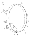
- the device insert 10 is intended to be level with the floor to be installed, for example in a cavity floor or in an installation unit of an installation duct.
- the use of equipment 10 has a cassette frame 12 and a cover 14.
- the Cassette frame 12 can stand with feet 16 on a ceiling surface support, and an upper edge of an edge 18 of the cassette frame 12 can be flush with a floor surface.
- the edge 18 defines a circular recess in which the lid 14 can be used.
- the cover 14 has a base plate 20 and a circular edge 22, the lid edge 22 and the base plate 20 define a recess which is to receive a Flooring is provided.
- cord outlet flap 24 integrated, which in a closed position, which is shown in FIG. 1 is shown, and can be locked in an open position can.
- the opened cord outlet flap 24 can be used in the device 10 arranged installation devices with end devices in one Building.
- the device insert 10 In the installed state of the device insert 10 are therefore only those Top edge of the edge 18 of the cassette frame, the top edge of the Edge 22 of the lid 14 and the cord outlet flap 24 are visible.
- the device insert 10 consists entirely of stainless steel sheet with a thickness of 2mm, the visible ones when installed Edges of edges 18 and 22 as well as the surface of the cord outlet flap 24 can be brushed.
- the cassette frame 12 is the cassette frame 12 of FIG. 1 shown with the cover removed.
- the cassette frame 12 consists of the edge 18 and a base part 26. Both the edge 18 and the base part 26 are as a one-piece bent sheet metal part educated.
- the base part 26 has a base plate 28 which is parallel is arranged to the upper edge of the edge 18. When installed of the cassette frame 12, the base plate 28 is thus parallel to a floor surface.
- the base plate 28 is provided with a central rectangular recess provided in the installation devices or device cups be arranged for the arrangement of installation devices can. To do this, go on opposite sides of the central one Recess from the base plate 28 locking conductors 30, between the Device cups or installation devices can be hung.
- each side of the central recess 32 there is a support in the middle of each side of the central recess 32 provided, each one starting from the base plate 28 and opposite this first support section bent at right angles 34, a holding section 36 and a second support section 38.
- the holding section 36 is opposite the first support section 34 bent at right angles and thus runs parallel to the base plate 28.
- the second extends Support section 38 vertically upwards and is therefore perpendicular to Base plate 28 arranged.
- To the first support section 34 is the second Support section 38 arranged at right angles.
- the first support section 34 is at two on opposite sides of the central recess horizontal supports 32 provided with the locking conductors 30.
- the second support section 38 lies with its narrow side on the underside of the base plate 28 on.
- a threaded bushing 40 is arranged in each holding section 36, into which an adjusting threaded bolt 42 is screwed.
- a foot 44 may be provided at his the Base plate 28 facing away from the end of the threaded stud 42.
- Each foot 44 has an elongated hole 46, to connect the foot 44 to a ceiling surface by means of screws.
- A can be between the foot 44 and the holding portion 36
- Lock nut 48 may be provided on the threaded adjustment bolt 42.
- the threaded adjustment bolt 48 has on its, the base plate 28 facing away End a conventional screw head in and of itself which is held in the base 44 by means of three projections 50 becomes.
- the projections 50 can come from the foot 44 on three sides punched out and bent out of the plane of the foot 44.
- the thread adjustment bolts 42 can thereby from the top of the base plate 28 by means of a screwdriver be adjusted.
- FIG. 3 shows the cassette frame 12 in an exploded view.
- the circular base plate 28 on its outer circumference Has projections 56 equally spaced apart.
- the Projections 56 have seen one in the plane of the base plate 28 rectangular cross section and run parallel to the base plate 28.
- the base plate 28 can therefore with the projections 28 made of plate material be cut out, for example by means of a laser.
- the locking conductors 30, the first support sections 34, the holding sections 36 and the second support portions 38 can be together with the base plate 28 cut out of plate material and then into the in Fig. 3 position shown are bent.
- the edge 18 consists of a curved material strip and has, in the region of its long side, which in the assembled state rests against the circumference of the base plate 28, has evenly spaced rectangular recesses 58.
- the recesses 58 are intended to receive the projections 56 on the base plate 28 and thereby produce a positive connection between the base plate 28 and the edge 18. Since the edge 18 is designed as a material strip, it can also be cut out of plate material by means of a laser. This also applies to the recesses 58.
- the material strip from which the edge 18 is formed is provided with a projection 60 or a suitable recess 62. In the state shown in FIG.
- the projection 60 engages in an undercut in the recess 62, so that the material strip is closed to form a ring and can transmit tensile and compressive forces over its entire circumference in the plane of the material strip.
- the material strip forming the edge 18 is bent round after being cut out of plate material in such a way that it is prestressed into the position shown in FIG. 3, which corresponds to the position mounted on the base plate 28.
- the edge 18 is bent open by the projection 60 being led out of the recess 62.
- the ring bent up in this way can now be attached to the base plate 28 such that a projection 56 engages in a recess 58 at the edge 18.
- the projection 60 is pressed back into the recess 62, this being supported by the pretensioning of the edge 18. Thereafter, the edge 18 forms a stable connection with the base plate 28 of the base part 26, without soldering, welding or adhesive connections between the base plate 28 and the edge 18 being necessary.
- the cassette frame 12 is variable in height with respect to a floor surface to be ordered.
- the holding sections 36 with the threaded bushes 40 are around the intended maximum height adjustment range lowered relative to the base plate 28.
- the distance between the holding sections 36 and the base plate 28 is fifty millimeters.
- the cassette frame is in the position shown in FIG. 2 12 thus approximately in the lowest possible position, i.e. so as close as possible to a floor surface on which feet 44 stand. Even in this, lowest position, the heads of the thread adjustment bolts are 42 not or only insignificantly above the level of Surface of the base plate 28 also.
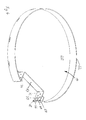
- the cover 14 is shown in perspective, however without the cord outlet flap 24. It can be clearly seen that the Cover 14, the cover base plate 20 and the associated edge 22 has. In contrast to the edge of the cassette frame, it runs Edge 22 of the cover 14 does not have a 360 ° angle, but leaves a peripheral area free for the arrangement of the cord outlet flap.
- the cord outlet flap is open on three sides Frame by means of an angled perpendicular to the base plate 20
- the material strip 64 forms three sides of a rectangular frame in the radial direction of the Base plate 20 is open to the outside.
- the radially outside Narrow sides of the material strip 64 forming the open frame are each provided with two projections 66, one between them Define recess.
- the upper protrusion 66 is beyond spaced from the top edge of the material strip 64.
- the Narrow sides of the material strip forming the edge 22 of the cover 14 are each with short on the top or bottom edge Projections 68 and with a centrally arranged projection 70 Mistake. In a recess between a projection 68 and the central projection 70, a projection 66 is received in each case.
- the projections 66, 68 and 70 there is a positive connection achieved between the material strip 64 and the edge 22. to Securing this positive connection becomes the central advantage 70 bent substantially at right angles so that it is parallel to a section 72 or 74 of the material strip 64.
- the projection 70 is then attached, for example by Insert a blind rivet. Form the base plate 20 and the edge 22 thereby a very stable unit, into which even heavy floor coverings, for example, stone slabs can be inserted.
- the edge 22 is mounted on the base plate 20 in a manner similar to that described in connection with FIG. 3.
- the edge 22 is cut out of plate-shaped material by means of a laser and is then bent round so that it fits into the Base plate 20 is biased assembled position.
- the central protrusions 70 on the narrow sides of the strip of material forming the edge 22 are angled towards the material strip itself and each have a bore 76 for receiving a blind rivet.
- edge 22 In the area of a long side of the material strip forming the edge 22 rectangular recesses 78 are provided which fit over shaped rectangular projections 80 on the circumference of the base plate 20 are performed. After engaging all the protrusions 80 in the recesses 78 and the engagement of the projections 66, 68 and 70 in the corresponding recesses are the base plate 20 and the edge 22 is positively connected and form a stable unit. The connection of the edge 22 to the base plate 20 is done by setting a blind rivet into the bore 76 of the projection 70 and the bore 82 secured in the material strip 64.
- the cord outlet flap 24 After connecting the base plate 20 to the edge 22, the Cord outlet flap 24 in the three-sided frame through the strip of material 64 is formed, are used.
- the cord outlet flap 24 has a flap part 84, which on its, in the installed state visible surface is provided with a decorative sheet 86.
- the decorative sheet 86 is punctured onto the flap part 84, for example.
- the flap part 84 can be pivoted by means of two cylinder screws 88 mounted on the material strip 64 of the base plate 20. This is the flap part 84 with two threaded bores lying on a pivot axis 90 provided, into each of which a screw 88 is screwed becomes.
- the cap screws 88 are only so far screwed in that its end is still within the threaded hole 90 is located and is not laterally beyond the flap part 84.
- the flap part 84 in the three-sided open frame the is formed by the material strip 64, inserted and the cheese head screws 88 are further screwed into the threaded bores 90, until their ends in the bores 92 on the end faces of the three-sided Frame come to rest.
- the flap part 84 is pivotable arranged on the lid 14. Since the cap screws 88 of the inside of the flap part 84 into the bores 92 on the material strip 64 can be screwed in, the cord outlet flap can also can then be easily replaced when the lid 14 already is provided with a floor covering. This allows the cord outlet flap 24 can be easily replaced if damaged.
- the flap part 84 has two further, opposite one another Bores 94, which are provided for the arrangement of sleeves 100, in which a spring-loaded ball is slidably housed.
- the Spring-loaded ball arranged in the sleeve 100 can, depending on the position the cord outlet flap 84, into the position bores 96 or 98 the material strip 64 into place.
- the holes 96 are one closed position of the cord outlet flap 24 and the holes 98 assigned to an open position of the cord outlet flap 24. Only one of the sleeves 100 to be arranged in the bores 94 with spring-loaded ball is indicated schematically in Fig. 5.
Landscapes
- Engineering & Computer Science (AREA)
- Architecture (AREA)
- Civil Engineering (AREA)
- Structural Engineering (AREA)
- Installation Of Indoor Wiring (AREA)
- Connection Of Plates (AREA)
- Connector Housings Or Holding Contact Members (AREA)
- Fittings On The Vehicle Exterior For Carrying Loads, And Devices For Holding Or Mounting Articles (AREA)
- Holding Or Fastening Of Disk On Rotational Shaft (AREA)
- Inspection Of Paper Currency And Valuable Securities (AREA)
- Electrical Discharge Machining, Electrochemical Machining, And Combined Machining (AREA)
- Adornments (AREA)
Applications Claiming Priority (2)
| Application Number | Priority Date | Filing Date | Title |
|---|---|---|---|
| DE20117522U DE20117522U1 (de) | 2001-09-03 | 2001-09-03 | Geräteeinsatz |
| DE20022577U | 2001-09-03 |
Publications (3)
| Publication Number | Publication Date |
|---|---|
| EP1289089A2 true EP1289089A2 (fr) | 2003-03-05 |
| EP1289089A3 EP1289089A3 (fr) | 2004-03-31 |
| EP1289089B1 EP1289089B1 (fr) | 2007-05-09 |
Family
ID=7963291
Family Applications (1)
| Application Number | Title | Priority Date | Filing Date |
|---|---|---|---|
| EP02000319A Expired - Lifetime EP1289089B1 (fr) | 2001-09-03 | 2002-01-04 | Support d'appareil encastré |
Country Status (4)
| Country | Link |
|---|---|
| EP (1) | EP1289089B1 (fr) |
| AT (1) | ATE362212T1 (fr) |
| DE (1) | DE20117522U1 (fr) |
| ES (1) | ES2286165T3 (fr) |
Cited By (1)
| Publication number | Priority date | Publication date | Assignee | Title |
|---|---|---|---|---|
| EP1583195A1 (fr) * | 2004-03-30 | 2005-10-05 | Novar GmbH | Boíte souterraine |
Families Citing this family (1)
| Publication number | Priority date | Publication date | Assignee | Title |
|---|---|---|---|---|
| DE20319362U1 (de) | 2003-12-11 | 2004-03-04 | Novar Gmbh | Kassettendeckel |
Family Cites Families (5)
| Publication number | Priority date | Publication date | Assignee | Title |
|---|---|---|---|---|
| DE6906706U (de) * | 1969-02-20 | 1969-06-19 | Siemens Ag | Bodendose fuer elektrische unterflur-installationen |
| US3603048A (en) | 1970-04-02 | 1971-09-07 | Textron Inc | Carpet-underfloor adapter |
| DE7342678U (de) | 1973-11-30 | 1974-04-18 | Traupe H | Hilfsmittel zur herstellung eines schachtes fuer unterflur- und unterputzinstallationen |
| DE9410742U1 (de) | 1994-07-08 | 1994-10-27 | Fa. Bader, 89250 Senden | Einbaukasten |
| DE29613888U1 (de) * | 1996-08-10 | 1996-10-10 | Albert Ackermann GmbH & Co. KG, 51643 Gummersbach | Vorrichtung zum Verschließen von gebohrten Kabelauslaßöffnungen |
-
2001
- 2001-09-03 DE DE20117522U patent/DE20117522U1/de not_active Expired - Lifetime
-
2002
- 2002-01-04 AT AT02000319T patent/ATE362212T1/de active
- 2002-01-04 EP EP02000319A patent/EP1289089B1/fr not_active Expired - Lifetime
- 2002-01-04 ES ES02000319T patent/ES2286165T3/es not_active Expired - Lifetime
Cited By (1)
| Publication number | Priority date | Publication date | Assignee | Title |
|---|---|---|---|---|
| EP1583195A1 (fr) * | 2004-03-30 | 2005-10-05 | Novar GmbH | Boíte souterraine |
Also Published As
| Publication number | Publication date |
|---|---|
| ES2286165T3 (es) | 2007-12-01 |
| ATE362212T1 (de) | 2007-06-15 |
| EP1289089A3 (fr) | 2004-03-31 |
| EP1289089B1 (fr) | 2007-05-09 |
| DE20117522U1 (de) | 2002-01-17 |
Similar Documents
| Publication | Publication Date | Title |
|---|---|---|
| AT522656B1 (de) | Möbelantrieb | |
| EP3346074B1 (fr) | Dispositif d'assemblage destiné à insérer des éléments de châssis dans des ouvertures des parois | |
| EP3818224A1 (fr) | Ferrure pour meuble | |
| DE2642167A1 (de) | Einstellbare querbalkenbaugruppe | |
| WO2018033221A1 (fr) | Charnière de meuble | |
| EP4278927A2 (fr) | Tiroir avec dispositif de maintien d'un panneau décoratif pouvant être placé sur la paroi latérale de tiroir | |
| EP1677012B1 (fr) | Pièce en plastique | |
| EP3612703B1 (fr) | Truelle de montage pour la pose de banquettes de fenêtre et procédé de montage d'une banquette de fenêtre avec cette truelle de montage | |
| DE1977564U (de) | Verbindungsteil. | |
| AT500268A1 (de) | Schneidemaschine für lebensmittel | |
| DE3871807T2 (de) | Scharnier. | |
| EP1289089B1 (fr) | Support d'appareil encastré | |
| EP2233039B1 (fr) | Guidage pour tiroirs | |
| EP2320022B1 (fr) | Charnière pour une grille de protection contre les insectes et/ou le pollen | |
| EP3913156B1 (fr) | Utilisation d'un cadre de fixation pour un dispositif d'actionnement ou pour une imitation d'un dispositif d'actionnement destiné au fonctionnement d'une installation sanitaire | |
| DE29612358U1 (de) | Möbelscharnier | |
| DE19605991A1 (de) | Eckverbindungsmaschine zur Herstellung von Fenster- und/oder Türrahmen | |
| DE29621665U1 (de) | Beschlag für die Halterung eines Endes einer Latte eines Lattenrahmens | |
| AT413583B (de) | Stabilisierungsvorrichtung für möbelteile | |
| DE202011000300U1 (de) | Frontblende für Möbel | |
| EP3296486B1 (fr) | Revetement de batiment avec une ferrure d'assemblage pour l'assemblage d'éléments allongés de recouvrement | |
| DE19514867C2 (de) | Scharnier für Fenster, Türen od. dgl., insbesondere für Dreh-Kippbeschläge mit einer Ausstellvorrichtung | |
| DE20120238U1 (de) | Montageplatte zur verstellbaren Halterung von Möbelscharnieren am Korpus von Möbelstücken | |
| EP2540942B1 (fr) | Agencement de ferrure réglable | |
| EP0933597A1 (fr) | Griffe pour support de radiateurs |
Legal Events
| Date | Code | Title | Description |
|---|---|---|---|
| PUAI | Public reference made under article 153(3) epc to a published international application that has entered the european phase |
Free format text: ORIGINAL CODE: 0009012 |
|
| AK | Designated contracting states |
Kind code of ref document: A2 Designated state(s): AT BE CH CY DE DK ES FI FR GB GR IE IT LI LU MC NL PT SE TR Designated state(s): AT BE CH CY DE DK ES FI FR GB GR IE IT LI LU MC NL PT SE TR |
|
| AX | Request for extension of the european patent |
Extension state: AL LT LV MK RO SI |
|
| PUAL | Search report despatched |
Free format text: ORIGINAL CODE: 0009013 |
|
| AK | Designated contracting states |
Kind code of ref document: A3 Designated state(s): AT BE CH CY DE DK ES FI FR GB GR IE IT LI LU MC NL PT SE TR |
|
| AX | Request for extension of the european patent |
Extension state: AL LT LV MK RO SI |
|
| 17P | Request for examination filed |
Effective date: 20040422 |
|
| AKX | Designation fees paid |
Designated state(s): AT BE CH CY DE DK ES FI FR GB GR IE IT LI LU MC NL PT SE TR |
|
| RAP1 | Party data changed (applicant data changed or rights of an application transferred) |
Owner name: OBO BETTERMANN GMBH & CO. KG |
|
| GRAP | Despatch of communication of intention to grant a patent |
Free format text: ORIGINAL CODE: EPIDOSNIGR1 |
|
| GRAS | Grant fee paid |
Free format text: ORIGINAL CODE: EPIDOSNIGR3 |
|
| GRAA | (expected) grant |
Free format text: ORIGINAL CODE: 0009210 |
|
| AK | Designated contracting states |
Kind code of ref document: B1 Designated state(s): AT BE CH CY DE DK ES FI FR GB GR IE IT LI LU MC NL PT SE TR |
|
| REG | Reference to a national code |
Ref country code: GB Ref legal event code: FG4D Free format text: NOT ENGLISH |
|
| REG | Reference to a national code |
Ref country code: CH Ref legal event code: EP |
|
| REG | Reference to a national code |
Ref country code: IE Ref legal event code: FG4D Free format text: LANGUAGE OF EP DOCUMENT: GERMAN |
|
| REF | Corresponds to: |
Ref document number: 50210107 Country of ref document: DE Date of ref document: 20070621 Kind code of ref document: P |
|
| PG25 | Lapsed in a contracting state [announced via postgrant information from national office to epo] |
Ref country code: SE Free format text: LAPSE BECAUSE OF FAILURE TO SUBMIT A TRANSLATION OF THE DESCRIPTION OR TO PAY THE FEE WITHIN THE PRESCRIBED TIME-LIMIT Effective date: 20070809 |
|
| REG | Reference to a national code |
Ref country code: CH Ref legal event code: NV Representative=s name: ZIMMERLI, WAGNER & PARTNER AG |
|
| GBT | Gb: translation of ep patent filed (gb section 77(6)(a)/1977) |
Effective date: 20070821 |
|
| ET | Fr: translation filed | ||
| REG | Reference to a national code |
Ref country code: ES Ref legal event code: FG2A Ref document number: 2286165 Country of ref document: ES Kind code of ref document: T3 |
|
| REG | Reference to a national code |
Ref country code: IE Ref legal event code: FD4D |
|
| PG25 | Lapsed in a contracting state [announced via postgrant information from national office to epo] |
Ref country code: IE Free format text: LAPSE BECAUSE OF FAILURE TO SUBMIT A TRANSLATION OF THE DESCRIPTION OR TO PAY THE FEE WITHIN THE PRESCRIBED TIME-LIMIT Effective date: 20070509 Ref country code: PT Free format text: LAPSE BECAUSE OF FAILURE TO SUBMIT A TRANSLATION OF THE DESCRIPTION OR TO PAY THE FEE WITHIN THE PRESCRIBED TIME-LIMIT Effective date: 20071009 Ref country code: DK Free format text: LAPSE BECAUSE OF FAILURE TO SUBMIT A TRANSLATION OF THE DESCRIPTION OR TO PAY THE FEE WITHIN THE PRESCRIBED TIME-LIMIT Effective date: 20070509 |
|
| PLBE | No opposition filed within time limit |
Free format text: ORIGINAL CODE: 0009261 |
|
| STAA | Information on the status of an ep patent application or granted ep patent |
Free format text: STATUS: NO OPPOSITION FILED WITHIN TIME LIMIT |
|
| 26N | No opposition filed |
Effective date: 20080212 |
|
| PG25 | Lapsed in a contracting state [announced via postgrant information from national office to epo] |
Ref country code: GR Free format text: LAPSE BECAUSE OF FAILURE TO SUBMIT A TRANSLATION OF THE DESCRIPTION OR TO PAY THE FEE WITHIN THE PRESCRIBED TIME-LIMIT Effective date: 20070810 |
|
| PGFP | Annual fee paid to national office [announced via postgrant information from national office to epo] |
Ref country code: CH Payment date: 20080124 Year of fee payment: 7 |
|
| PGFP | Annual fee paid to national office [announced via postgrant information from national office to epo] |
Ref country code: FI Payment date: 20080122 Year of fee payment: 7 |
|
| BERE | Be: lapsed |
Owner name: OBO BETTERMANN G.M.B.H. & CO. KG Effective date: 20080131 |
|
| PG25 | Lapsed in a contracting state [announced via postgrant information from national office to epo] |
Ref country code: MC Free format text: LAPSE BECAUSE OF NON-PAYMENT OF DUE FEES Effective date: 20080131 |
|
| PG25 | Lapsed in a contracting state [announced via postgrant information from national office to epo] |
Ref country code: BE Free format text: LAPSE BECAUSE OF NON-PAYMENT OF DUE FEES Effective date: 20080131 |
|
| PG25 | Lapsed in a contracting state [announced via postgrant information from national office to epo] |
Ref country code: CY Free format text: LAPSE BECAUSE OF FAILURE TO SUBMIT A TRANSLATION OF THE DESCRIPTION OR TO PAY THE FEE WITHIN THE PRESCRIBED TIME-LIMIT Effective date: 20070509 |
|
| REG | Reference to a national code |
Ref country code: CH Ref legal event code: PL |
|
| PG25 | Lapsed in a contracting state [announced via postgrant information from national office to epo] |
Ref country code: CH Free format text: LAPSE BECAUSE OF NON-PAYMENT OF DUE FEES Effective date: 20090131 Ref country code: FI Free format text: LAPSE BECAUSE OF NON-PAYMENT OF DUE FEES Effective date: 20090104 Ref country code: LI Free format text: LAPSE BECAUSE OF NON-PAYMENT OF DUE FEES Effective date: 20090131 |
|
| PG25 | Lapsed in a contracting state [announced via postgrant information from national office to epo] |
Ref country code: LU Free format text: LAPSE BECAUSE OF NON-PAYMENT OF DUE FEES Effective date: 20080104 |
|
| PG25 | Lapsed in a contracting state [announced via postgrant information from national office to epo] |
Ref country code: TR Free format text: LAPSE BECAUSE OF FAILURE TO SUBMIT A TRANSLATION OF THE DESCRIPTION OR TO PAY THE FEE WITHIN THE PRESCRIBED TIME-LIMIT Effective date: 20070509 |
|
| REG | Reference to a national code |
Ref country code: FR Ref legal event code: PLFP Year of fee payment: 15 |
|
| REG | Reference to a national code |
Ref country code: FR Ref legal event code: PLFP Year of fee payment: 16 |
|
| REG | Reference to a national code |
Ref country code: FR Ref legal event code: PLFP Year of fee payment: 17 |
|
| PGFP | Annual fee paid to national office [announced via postgrant information from national office to epo] |
Ref country code: FR Payment date: 20210120 Year of fee payment: 20 Ref country code: NL Payment date: 20210120 Year of fee payment: 20 |
|
| PGFP | Annual fee paid to national office [announced via postgrant information from national office to epo] |
Ref country code: AT Payment date: 20210119 Year of fee payment: 20 Ref country code: DE Payment date: 20210121 Year of fee payment: 20 Ref country code: GB Payment date: 20210122 Year of fee payment: 20 Ref country code: ES Payment date: 20210217 Year of fee payment: 20 |
|
| PGFP | Annual fee paid to national office [announced via postgrant information from national office to epo] |
Ref country code: IT Payment date: 20210129 Year of fee payment: 20 |
|
| REG | Reference to a national code |
Ref country code: DE Ref legal event code: R071 Ref document number: 50210107 Country of ref document: DE |
|
| REG | Reference to a national code |
Ref country code: NL Ref legal event code: MK Effective date: 20220103 |
|
| REG | Reference to a national code |
Ref country code: GB Ref legal event code: PE20 Expiry date: 20220103 |
|
| PG25 | Lapsed in a contracting state [announced via postgrant information from national office to epo] |
Ref country code: GB Free format text: LAPSE BECAUSE OF EXPIRATION OF PROTECTION Effective date: 20220103 |
|
| REG | Reference to a national code |
Ref country code: AT Ref legal event code: MK07 Ref document number: 362212 Country of ref document: AT Kind code of ref document: T Effective date: 20220104 |
|
| REG | Reference to a national code |
Ref country code: ES Ref legal event code: FD2A Effective date: 20220418 |
|
| PG25 | Lapsed in a contracting state [announced via postgrant information from national office to epo] |
Ref country code: ES Free format text: LAPSE BECAUSE OF EXPIRATION OF PROTECTION Effective date: 20220105 |