EP4278927A2 - Tiroir avec dispositif de maintien d'un panneau décoratif pouvant être placé sur la paroi latérale de tiroir - Google Patents
Tiroir avec dispositif de maintien d'un panneau décoratif pouvant être placé sur la paroi latérale de tiroir Download PDFInfo
- Publication number
- EP4278927A2 EP4278927A2 EP23201844.0A EP23201844A EP4278927A2 EP 4278927 A2 EP4278927 A2 EP 4278927A2 EP 23201844 A EP23201844 A EP 23201844A EP 4278927 A2 EP4278927 A2 EP 4278927A2
- Authority
- EP
- European Patent Office
- Prior art keywords
- holding
- legs
- decorative plate
- decorative
- drawer
- Prior art date
- Legal status (The legal status is an assumption and is not a legal conclusion. Google has not performed a legal analysis and makes no representation as to the accuracy of the status listed.)
- Granted
Links
Images


Classifications
-
- A—HUMAN NECESSITIES
- A47—FURNITURE; DOMESTIC ARTICLES OR APPLIANCES; COFFEE MILLS; SPICE MILLS; SUCTION CLEANERS IN GENERAL
- A47B—TABLES; DESKS; OFFICE FURNITURE; CABINETS; DRAWERS; GENERAL DETAILS OF FURNITURE
- A47B88/00—Drawers for tables, cabinets or like furniture; Guides for drawers
- A47B88/90—Constructional details of drawers
- A47B88/919—Accessories or additional elements for drawers, e.g. drawer lighting
- A47B88/925—Additional side walls mountable on existing side walls
-
- A—HUMAN NECESSITIES
- A47—FURNITURE; DOMESTIC ARTICLES OR APPLIANCES; COFFEE MILLS; SPICE MILLS; SUCTION CLEANERS IN GENERAL
- A47B—TABLES; DESKS; OFFICE FURNITURE; CABINETS; DRAWERS; GENERAL DETAILS OF FURNITURE
- A47B88/00—Drawers for tables, cabinets or like furniture; Guides for drawers
- A47B88/90—Constructional details of drawers
- A47B2088/902—Corner connectors for drawers
-
- A—HUMAN NECESSITIES
- A47—FURNITURE; DOMESTIC ARTICLES OR APPLIANCES; COFFEE MILLS; SPICE MILLS; SUCTION CLEANERS IN GENERAL
- A47B—TABLES; DESKS; OFFICE FURNITURE; CABINETS; DRAWERS; GENERAL DETAILS OF FURNITURE
- A47B88/00—Drawers for tables, cabinets or like furniture; Guides for drawers
- A47B88/90—Constructional details of drawers
- A47B88/944—Drawers characterised by the front panel
- A47B88/95—Drawers characterised by the front panel characterised by connection means for the front panel
- A47B2088/952—Drawers characterised by the front panel characterised by connection means for the front panel having two parts and using a screw
Definitions
- the invention further relates to an attachment device for a drawer side wall, wherein a surface of the drawer side wall can be enlarged by the attachment device in a direction transverse to a longitudinal direction of the drawer side wall and wherein the attachment device has at least one, preferably two, holding device (s) of the type to be described.
- the invention relates to a method for mounting a decorative panel on at least one holding device of the type to be described.
- a generic holding device for holding a decorative panel for drawers is, for example, in WHERE 2015/192154 A1 shown.
- the decorative plate is used to increase the storage volume of a drawer and can be made as a decorative insert made of glass, wood, stone, plastic or ceramic.
- a hole is arranged in the front and rear end region of the decorative plate, with a pin of a metal reinforcement on a first side of the decorative plate and a sleeve of an additional holder engaging in the hole in the decorative plate on an opposite second side of the decorative plate.
- the disadvantage of this is that producing a hole in the decorative panel involves considerable additional effort.
- the production of the hole in the decorative panel also involves the risk that the decorative panel will crack during the drilling process and can therefore no longer be used.
- Drawers with a holding device for attaching a plate-shaped wall element are in the EP 2 637 524 A1 , WO 2016/131579 A1 , EP 2 398 350 A1 and in the EP 3 009 040 A1 shown.
- These holding devices each comprise a substantially U-shaped component with two side legs, between which the plate-shaped wall element can be arranged.
- the disadvantage of this is that the U-shaped component must be precisely matched to the dimensions of the wall element for a play-free attachment of the plate-shaped wall element. Otherwise there is a risk that the wall element will wobble when assembled and will make annoying noises when the drawer moves (particularly when it reaches the two end positions).
- the object of the present invention is to provide a holding device of the type mentioned at the outset while avoiding the disadvantages discussed above.
- the clamping device comprises at least one adjusting device, through which the clamping force that can be exerted on the decorative panel between the at least two holding legs can be adjusted.
- the decorative panel in a mounted state, is held in position by clamping on the holding device by the at least two holding legs.
- the decorative panel can therefore be designed to be completely free of openings or depressions.
- the provision of such an adjustment device has the advantage that the clamping force of the holding legs exerted on the decorative panel can be variably adjusted by a user and can be optimally (ie, without play) adapted to the respective dimensions of the decorative panel.
- the adjusting device also offers, for example, the possibility of adjusting the clamping force of the holding legs at a to increase the decorative panel that has become loose, so that the decorative panel can be fixed again by clamping.
- the adjusting device can, for example, comprise at least one clamping screw that is connected or connectable to the at least two holding legs.
- the adjusting device can also have a rotatably mounted adjusting wheel or a movably mounted clamping element for non-positively fixing the decorative panel.
- the at least two holding legs of the holding device can be made, for example, from a metallic material.
- the surface of the holding legs intended for contact with the decorative panel can be provided with a surface coating, which increases the static friction and enables the holding legs to rest softly on the decorative panel.
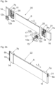
- Fig. 1a shows a drawer 1 in an exploded view.
- the drawer 1 has two drawer side walls 2a, 2b, a front panel 3, a drawer rear wall 4 and a drawer bottom 5.
- decorative panels 6 are provided, which can be placed on the side walls 2a, 2b and can be made, for example, from glass, stone, wood, ceramic, plastic, plastic or a composite material (in particular a composite glass).
- the cuboid decorative panels 6 can be detachably connected via holding devices 7a, 7b on the one hand to the front panel 3 and on the other hand to the drawer rear wall 4.
- the holding devices 7a, 7b each have a fastening device 8a, 8b, the front fastening device 8a being designed for fastening to the front panel 3 and the rear fastening device 8b to be fastened to the drawer rear wall 4.
- the front fastening device 8a is connected to a front panel 3 fastening, preferably pin-shaped, fitting element 9 can be detachably connected, preferably lockable.
- the rear fastening device 8b can be releasably connectable, preferably lockable, to openings 10 arranged on the drawer rear wall 4.
- Fig. 1b shows the in Fig. 1a Drawer 1 shown in an assembled state.
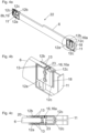
- Fig. 2a shows an exploded view of an attachment device 22 for the drawer side wall 2a, 2b, with the attachment device 22 allowing an area of the drawer side wall 2a, 2b to be enlarged in a direction transverse to a longitudinal direction (L) of the drawer side wall 2a, 2b.
- the holding devices 7a, 7b each have a base body 11, which has a receiving chamber 20 for receiving an end section of the decorative panel 6.
- a storage device 18 for storing two holding legs 12a, 12b is also arranged on the base body 11.
- the decorative plate 6 can be picked up in sections between the two holding legs 12a, 12b, the at least two holding legs 12a, 12b being part of a clamping device 15, through which a clamping force is applied in a direction transverse to a longitudinal direction (L) of the decorative plate 6 between the at least two holding legs 12a, 12b accommodated decorative plate 6 can be exercised.
- the decorative panel 12a, 12b is held in a clamping manner in its assembled state by the two holding legs 12a, 12b.
- they are: at least two holding legs 12a, 12b are connected to one another or can be connected to one another via at least one cross leg 12c.
- the clamping device 15 comprises at least one adjusting device 16, through which a clamping force that can be exerted on the decorative panel 6 between the at least two holding legs 12a, 12b can be adjusted.
- the adjusting device 16 can comprise at least one clamping screw 16a that is connected or connectable to the at least two holding legs 12a, 12b.
- At least one covering device 14 can be provided, through which at least the two holding legs 12a, 12b of the holding device 7a, 7b can be covered. According to one exemplary embodiment, it can be provided that the at least two holding legs 12a, 12b can be clamped to the decorative panel 6 by placing the at least one cover device 14 over the at least two holding legs 12a, 12b.
- the fastening device 8a, 8b for fastening the holding device 7a, 7b to the front panel 3 or to the drawer rear wall 4 can, for example, have a hole 21, preferably a keyhole, for inserting the fitting element 9 to be attached to the front panel 3 and / or at least one locking projection 19 for Attach the drawer back wall 4.
- the at least one locking projection 19 is designed such that it fits into a corresponding opening 10 ( Fig. 1a ) the drawer rear wall 4 can be snapped into place.
- the base body 11 can have at least one spring element (not shown here), through which play occurring in the longitudinal direction (L) of the decorative panel 6 can be at least partially compensated.
- the spring element can be formed, for example, by an elastically flexible piece of material or by a shaped spring.
- Fig. 3a shows the decorative plate 6, with the two holding legs 12a, 12b of the holding device 7a, 7b clamping around the decorative plate 6.
- the clamping force that can be exerted on the decorative panel 6 between the holding legs 12a, 12b can be adjusted by the adjusting device 16.
- the clamping force can be variably adjusted by rotating the two clamping screws 16a using a tool.
- Fig. 3b shows the in Fig. 3a circled area in an enlarged view.
- Fig. 3c shows an embodiment not according to the invention, wherein the two holding legs 12a, 12b hold the decorative panel 6 grasp in a clamping manner. Unlike the one in the Fig. 3a, 3b In the exemplary embodiment shown, the adjusting device 16 is omitted here. The two holding legs 12a, 12b therefore rest against the decorative plate 6 with a preload. This can be solved, for example, in that the two holding legs 12a, 12b can be spread apart relative to one another by receiving the decorative plate 6.
- the holding device 7a, 7b comprises at least one base body 11 and the at least two holding legs 12a, 12b each have a first end, at which the holding legs 12a, 12b can be connected to the base body 11, and a second end, which can be placed on the decorative plate 6.
- a distance between the at least two holding legs 12a, 12b decreases in a direction transverse to a longitudinal direction (L) of the decorative panel 6 starting from the first ends in the direction of the second ends and the second ends of the at least two holding legs 12a , 12b can be spread apart relative to one another by receiving the decorative plate 6.
- Figs. 4a-4c show the attachment device 22 in three different cross-sectional views, the height of the drawer side wall 2a, 2b and thus the storage volume of the drawer 1 being able to be increased by the attachment device 22.
- Fig. 4a shows a perspective section of the attachment device 22, the two end regions of the decorative plate 6 each being supported by the two holding legs 12a, 12b be grasped in a clamping manner.
- the two holding legs 12a, 12b are connected to one another via at least one cross leg 12c, so that the holding legs 12a, 12b together with the at least one cross leg 12c form a U-shaped clamp.
- the adjusting device 16 which has, for example, at least one clamping screw 16a, the effective clamping force of the holding legs 12a, 12b on the two outer sides of the decorative panel 6 can be adjusted.
- Fig. 4b shows the in Fig. 4a circled area in an enlarged view.
- the decorative panel 6 is fixed without play in its assembled state within the two retaining legs 12a, 12b in a direction transverse to the longitudinal direction (L) of the decorative panel 6.
- At least one limiting element 23 is arranged between the at least two holding legs 12a, 12b, through which the clamping force that can be exerted on the decorative plate 6 can be limited.
- the limiting element 23 forms a stop for the two holding legs 12a, 12b, so that excessive actuation of the adjusting device 16 is prevented.
- Fig. 4c shows the in Fig. 4b shown section of the attachment device 22 in a horizontal section.
- Figs. 5a-5c show the assembly of the holding devices 7a, 7b on the decorative panel 6.
- the base bodies 11 of the holding devices 7a, 7b each have a receiving chamber 20, which can be essentially rectangular in cross section.
- Fig. 5b show the holding devices 7a, 7b pushed onto the end sections of the decorative panel 6.
- the adjusting device 16 for adjusting the clamping force acting on the decorative panel 6 has not yet been actuated.
- Fig. 5c shows the decorative plate 6 with the holding devices 7a, 7b, which is non-positively fixed within the receiving chamber 20 by actuating the adjusting device 16, preferably the clamping screws 16a.
- the construction shown corresponds to the attachment device 22, through which the area of the drawer side wall 2a, 2b can be enlarged in a direction transverse to a longitudinal direction (L) of the drawer side wall 2a, 2b, the attachment device 22 having at least one, preferably two, holding device (s) 7a, 7b has.
- Figs. 6a-6e show the assembly of the attachment device 22 on the drawer 1.
- the front holding device 7a is pushed onto the fitting element 9 pre-assembled on the back of the front panel 3 ( Fig. 1b ).
- the rear end section of the decorative panel 6 is pivoted in the direction of the drawer side wall 2b until the rear holding device 7b can be locked to the drawer rear wall 4 ( Fig. 6c ).
- the two covering devices 14 are provided ( Fig. 6d ).
- the two covering devices 14 are pushed onto the holding devices 7a, 7b from above ( Fig. 6e ).
- the at least two holding legs 12a, 12b can be clamped to the decorative panel 6 by placing the at least one covering device 14 over the at least two holding legs 12a, 12b.
Landscapes
- Drawers Of Furniture (AREA)
- Supports Or Holders For Household Use (AREA)
Applications Claiming Priority (3)
| Application Number | Priority Date | Filing Date | Title |
|---|---|---|---|
| ATA50577/2020A AT523987B1 (de) | 2020-07-06 | 2020-07-06 | Haltevorrichtung zur Halterung einer auf eine Schubladenseitenwand aufsetzbaren Dekorplatte |
| PCT/AT2021/060217 WO2022006604A1 (fr) | 2020-07-06 | 2021-06-22 | Dispositif de maintien d'un panneau décoratif pouvant être placé sur une paroi latérale de tiroir |
| EP21739531.8A EP4175512B1 (fr) | 2020-07-06 | 2021-06-22 | Tiroir avec dispositif de maintien d'un panneau décoratif pouvant être placé sur la paroi latérale de tiroir |
Related Parent Applications (1)
| Application Number | Title | Priority Date | Filing Date |
|---|---|---|---|
| EP21739531.8A Division EP4175512B1 (fr) | 2020-07-06 | 2021-06-22 | Tiroir avec dispositif de maintien d'un panneau décoratif pouvant être placé sur la paroi latérale de tiroir |
Publications (3)
| Publication Number | Publication Date |
|---|---|
| EP4278927A2 true EP4278927A2 (fr) | 2023-11-22 |
| EP4278927A3 EP4278927A3 (fr) | 2024-02-28 |
| EP4278927B1 EP4278927B1 (fr) | 2025-08-06 |
Family
ID=76844939
Family Applications (2)
| Application Number | Title | Priority Date | Filing Date |
|---|---|---|---|
| EP23201844.0A Active EP4278927B1 (fr) | 2020-07-06 | 2021-06-22 | Tiroir avec dispositif de maintien d'un panneau décoratif pouvant être placé sur la paroi latérale de tiroir |
| EP21739531.8A Active EP4175512B1 (fr) | 2020-07-06 | 2021-06-22 | Tiroir avec dispositif de maintien d'un panneau décoratif pouvant être placé sur la paroi latérale de tiroir |
Family Applications After (1)
| Application Number | Title | Priority Date | Filing Date |
|---|---|---|---|
| EP21739531.8A Active EP4175512B1 (fr) | 2020-07-06 | 2021-06-22 | Tiroir avec dispositif de maintien d'un panneau décoratif pouvant être placé sur la paroi latérale de tiroir |
Country Status (8)
| Country | Link |
|---|---|
| US (1) | US11766120B2 (fr) |
| EP (2) | EP4278927B1 (fr) |
| JP (1) | JP7479559B2 (fr) |
| CN (1) | CN115701921B (fr) |
| AT (1) | AT523987B1 (fr) |
| ES (2) | ES3052609T3 (fr) |
| TW (1) | TWI789812B (fr) |
| WO (1) | WO2022006604A1 (fr) |
Families Citing this family (4)
| Publication number | Priority date | Publication date | Assignee | Title |
|---|---|---|---|---|
| TWI806690B (zh) * | 2022-07-04 | 2023-06-21 | 川湖科技股份有限公司 | 傢俱及其傢俱組件 |
| TWI806691B (zh) * | 2022-07-04 | 2023-06-21 | 川湖科技股份有限公司 | 傢俱及其傢俱組件 |
| TWI806689B (zh) | 2022-07-04 | 2023-06-21 | 川湖科技股份有限公司 | 傢俱及其傢俱組件 |
| TWI843467B (zh) * | 2023-03-06 | 2024-05-21 | 川湖科技股份有限公司 | 傢俱及其傢俱組件 |
Citations (5)
| Publication number | Priority date | Publication date | Assignee | Title |
|---|---|---|---|---|
| EP2398350A1 (fr) | 2009-02-17 | 2011-12-28 | Paul Hettich GmbH & Co. KG | Assemblage d'angle |
| EP2637524A1 (fr) | 2010-11-12 | 2013-09-18 | Paul Hettich GmbH & Co. KG | Tiroir |
| WO2015192154A1 (fr) | 2014-06-18 | 2015-12-23 | Julius Blum Gmbh | Tiroir |
| EP3009040A1 (fr) | 2014-10-16 | 2016-04-20 | Grass GmbH | Paroi pour tiroir |
| WO2016131579A1 (fr) | 2015-02-18 | 2016-08-25 | Grass Gmbh | Élément de recouvrement pour organe de fixation module i |
Family Cites Families (17)
| Publication number | Priority date | Publication date | Assignee | Title |
|---|---|---|---|---|
| AT391253B (de) | 1986-05-14 | 1990-09-10 | Blum Gmbh Julius | Beschlagbausatz fuer eine aus mehreren teilen zusammensetzbare schublade |
| AT387316B (de) * | 1987-02-16 | 1989-01-10 | Blum Gmbh Julius | Aus mehreren teilen zusammensetzbare schublade |
| DE3713254A1 (de) * | 1986-05-14 | 1987-11-19 | Blum Gmbh Julius | Schublade |
| AT395811B (de) * | 1986-05-14 | 1993-03-25 | Blum Gmbh Julius | Beschlagbausatz fuer eine schublade |
| ITPN20020070A1 (it) * | 2002-09-16 | 2004-03-17 | Livenza Ferramenta Srl | Dispositivo di supporto per mensole. |
| AT506440B1 (de) * | 2008-03-10 | 2012-10-15 | Blum Gmbh Julius | Schublade mit einer befestigungseinrichtung für wandelemente |
| DE102013106092B4 (de) * | 2013-06-12 | 2025-07-10 | Paul Hettich Gmbh & Co. Kg | Schubkasten mit Seitenzargen und einer justierbaren Frontblende |
| DE202015100770U1 (de) * | 2015-02-18 | 2016-05-19 | Grass Gmbh | Abdeckkappe oben offen Modul i |
| DE202015100773U1 (de) * | 2015-02-18 | 2016-05-19 | Grass Gmbh | Zarge für eine Schublade mit einem Zargenkörper, Schublade und Möbel |
| US20170258229A1 (en) * | 2016-03-14 | 2017-09-14 | Thermo Fisher Scientific (Asheville) Llc | Devices and methods for leveling shelves in a laboratory climatic cabinet |
| AT17134U1 (de) * | 2017-02-03 | 2021-06-15 | Blum Gmbh Julius | Schublade |
| DE102017105798A1 (de) * | 2017-03-17 | 2018-09-20 | Paul Hettich Gmbh & Co. Kg | Zarge für einen Schubkasten |
| DE102017105794A1 (de) * | 2017-03-17 | 2018-09-20 | Paul Hettich Gmbh & Co. Kg | Zarge für einen Schubkasten |
| JP6449420B1 (ja) | 2017-11-15 | 2019-01-09 | 榎本金属株式会社 | キッチン用オイルガード及びそれを備えたキッチン |
| EP3556249A1 (fr) * | 2018-04-19 | 2019-10-23 | Yaron Levi | Système de tiroir |
| DE102019122855A1 (de) * | 2019-08-26 | 2021-03-04 | Paul Hettich Gmbh & Co. Kg | Seitenzarge für einen Schubkasten |
| DE102020107663A1 (de) * | 2020-03-19 | 2021-09-23 | Paul Hettich Gmbh & Co. Kg | Möbel und Schubelement für ein Möbel |
-
2020
- 2020-07-06 AT ATA50577/2020A patent/AT523987B1/de active
-
2021
- 2021-06-22 ES ES23201844T patent/ES3052609T3/es active Active
- 2021-06-22 EP EP23201844.0A patent/EP4278927B1/fr active Active
- 2021-06-22 JP JP2023500280A patent/JP7479559B2/ja active Active
- 2021-06-22 WO PCT/AT2021/060217 patent/WO2022006604A1/fr not_active Ceased
- 2021-06-22 CN CN202180043197.5A patent/CN115701921B/zh active Active
- 2021-06-22 EP EP21739531.8A patent/EP4175512B1/fr active Active
- 2021-06-22 ES ES21739531T patent/ES2968631T3/es active Active
- 2021-07-05 TW TW110124585A patent/TWI789812B/zh active
-
2022
- 2022-12-06 US US18/075,724 patent/US11766120B2/en active Active
Patent Citations (5)
| Publication number | Priority date | Publication date | Assignee | Title |
|---|---|---|---|---|
| EP2398350A1 (fr) | 2009-02-17 | 2011-12-28 | Paul Hettich GmbH & Co. KG | Assemblage d'angle |
| EP2637524A1 (fr) | 2010-11-12 | 2013-09-18 | Paul Hettich GmbH & Co. KG | Tiroir |
| WO2015192154A1 (fr) | 2014-06-18 | 2015-12-23 | Julius Blum Gmbh | Tiroir |
| EP3009040A1 (fr) | 2014-10-16 | 2016-04-20 | Grass GmbH | Paroi pour tiroir |
| WO2016131579A1 (fr) | 2015-02-18 | 2016-08-25 | Grass Gmbh | Élément de recouvrement pour organe de fixation module i |
Also Published As
| Publication number | Publication date |
|---|---|
| TWI789812B (zh) | 2023-01-11 |
| US20230097170A1 (en) | 2023-03-30 |
| CN115701921B (zh) | 2025-12-26 |
| ES2968631T3 (es) | 2024-05-13 |
| EP4278927A3 (fr) | 2024-02-28 |
| TW202203814A (zh) | 2022-02-01 |
| JP2023532580A (ja) | 2023-07-28 |
| CN115701921A (zh) | 2023-02-14 |
| EP4175512A1 (fr) | 2023-05-10 |
| EP4278927B1 (fr) | 2025-08-06 |
| AT523987B1 (de) | 2022-04-15 |
| ES3052609T3 (en) | 2026-01-12 |
| JP7479559B2 (ja) | 2024-05-08 |
| EP4175512B1 (fr) | 2023-10-18 |
| US11766120B2 (en) | 2023-09-26 |
| AT523987A1 (de) | 2022-01-15 |
| WO2022006604A1 (fr) | 2022-01-13 |
Similar Documents
| Publication | Publication Date | Title |
|---|---|---|
| EP4175512B1 (fr) | Tiroir avec dispositif de maintien d'un panneau décoratif pouvant être placé sur la paroi latérale de tiroir | |
| EP3868255B1 (fr) | Agencement de tiroirs | |
| EP3957211B1 (fr) | Panneau avant pour un tiroir | |
| EP2729037B1 (fr) | Tiroir | |
| EP3727092B1 (fr) | Lisse de rambarde pour un tiroir | |
| EP2704604B1 (fr) | Tiroir | |
| AT515997B1 (de) | Anordnung mit Schubladenseitenwand und Halteteil | |
| EP2944224B1 (fr) | Étagère | |
| EP3238569B1 (fr) | Dispositif de pose d'une paroi arrière sur un élément de meuble mobile | |
| EP1677012A1 (fr) | Pièce en plastique | |
| EP3612703B1 (fr) | Truelle de montage pour la pose de banquettes de fenêtre et procédé de montage d'une banquette de fenêtre avec cette truelle de montage | |
| DE202009013488U1 (de) | Vorrichtung zum Fixieren eines Baukörpers in einer Gebäudeöffnung | |
| DE19821255A1 (de) | Befestigungsvorrichtung | |
| AT413583B (de) | Stabilisierungsvorrichtung für möbelteile | |
| WO2024016032A1 (fr) | Paroi latérale de tiroir | |
| DE29612358U1 (de) | Möbelscharnier | |
| EP3231327B1 (fr) | Dispositif de fixation d'un élément de réception sur un corps de meuble | |
| AT527376B1 (de) | Schubladenseitenwand für eine Schublade | |
| AT527377B1 (de) | Schubladenseitenwand für eine Schublade | |
| DE202023003058U1 (de) | Stabilisator zum Stabilisieren einer Scheibe | |
| EP4558010A1 (fr) | Paroi latérale de tiroir | |
| WO2025093301A1 (fr) | Tiroir et procédé permettant d'installer un élément décoratif | |
| EP2530336A1 (fr) | Dispositif de soutien de composants | |
| EP1289089A2 (fr) | Support d'appareil encastré | |
| DE20212290U1 (de) | Halterung zur Befestigung von Montagegestellen |
Legal Events
| Date | Code | Title | Description |
|---|---|---|---|
| PUAI | Public reference made under article 153(3) epc to a published international application that has entered the european phase |
Free format text: ORIGINAL CODE: 0009012 |
|
| STAA | Information on the status of an ep patent application or granted ep patent |
Free format text: STATUS: THE APPLICATION HAS BEEN PUBLISHED |
|
| AC | Divisional application: reference to earlier application |
Ref document number: 4175512 Country of ref document: EP Kind code of ref document: P |
|
| AK | Designated contracting states |
Kind code of ref document: A2 Designated state(s): AL AT BE BG CH CY CZ DE DK EE ES FI FR GB GR HR HU IE IS IT LI LT LU LV MC MK MT NL NO PL PT RO RS SE SI SK SM TR |
|
| P01 | Opt-out of the competence of the unified patent court (upc) registered |
Effective date: 20231207 |
|
| PUAL | Search report despatched |
Free format text: ORIGINAL CODE: 0009013 |
|
| AK | Designated contracting states |
Kind code of ref document: A3 Designated state(s): AL AT BE BG CH CY CZ DE DK EE ES FI FR GB GR HR HU IE IS IT LI LT LU LV MC MK MT NL NO PL PT RO RS SE SI SK SM TR |
|
| RIC1 | Information provided on ipc code assigned before grant |
Ipc: A47B 88/925 20170101AFI20240124BHEP |
|
| STAA | Information on the status of an ep patent application or granted ep patent |
Free format text: STATUS: REQUEST FOR EXAMINATION WAS MADE |
|
| 17P | Request for examination filed |
Effective date: 20240812 |
|
| RBV | Designated contracting states (corrected) |
Designated state(s): AL AT BE BG CH CY CZ DE DK EE ES FI FR GB GR HR HU IE IS IT LI LT LU LV MC MK MT NL NO PL PT RO RS SE SI SK SM TR |
|
| GRAP | Despatch of communication of intention to grant a patent |
Free format text: ORIGINAL CODE: EPIDOSNIGR1 |
|
| STAA | Information on the status of an ep patent application or granted ep patent |
Free format text: STATUS: GRANT OF PATENT IS INTENDED |
|
| INTG | Intention to grant announced |
Effective date: 20250303 |
|
| GRAS | Grant fee paid |
Free format text: ORIGINAL CODE: EPIDOSNIGR3 |
|
| GRAA | (expected) grant |
Free format text: ORIGINAL CODE: 0009210 |
|
| STAA | Information on the status of an ep patent application or granted ep patent |
Free format text: STATUS: THE PATENT HAS BEEN GRANTED |
|
| AC | Divisional application: reference to earlier application |
Ref document number: 4175512 Country of ref document: EP Kind code of ref document: P |
|
| AK | Designated contracting states |
Kind code of ref document: B1 Designated state(s): AL AT BE BG CH CY CZ DE DK EE ES FI FR GB GR HR HU IE IS IT LI LT LU LV MC MK MT NL NO PL PT RO RS SE SI SK SM TR |
|
| REG | Reference to a national code |
Ref country code: GB Ref legal event code: FG4D Free format text: NOT ENGLISH |
|
| REG | Reference to a national code |
Ref country code: CH Ref legal event code: EP |
|
| REG | Reference to a national code |
Ref country code: IE Ref legal event code: FG4D Free format text: LANGUAGE OF EP DOCUMENT: GERMAN |
|
| REG | Reference to a national code |
Ref country code: DE Ref legal event code: R096 Ref document number: 502021008275 Country of ref document: DE |
|
| REG | Reference to a national code |
Ref country code: NL Ref legal event code: MP Effective date: 20250806 |
|
| PG25 | Lapsed in a contracting state [announced via postgrant information from national office to epo] |
Ref country code: IS Free format text: LAPSE BECAUSE OF FAILURE TO SUBMIT A TRANSLATION OF THE DESCRIPTION OR TO PAY THE FEE WITHIN THE PRESCRIBED TIME-LIMIT Effective date: 20251206 |
|
| PG25 | Lapsed in a contracting state [announced via postgrant information from national office to epo] |
Ref country code: NO Free format text: LAPSE BECAUSE OF FAILURE TO SUBMIT A TRANSLATION OF THE DESCRIPTION OR TO PAY THE FEE WITHIN THE PRESCRIBED TIME-LIMIT Effective date: 20251106 |
|
| REG | Reference to a national code |
Ref country code: ES Ref legal event code: FG2A Ref document number: 3052609 Country of ref document: ES Kind code of ref document: T3 Effective date: 20260112 Ref country code: LT Ref legal event code: MG9D |
|
| PG25 | Lapsed in a contracting state [announced via postgrant information from national office to epo] |
Ref country code: PT Free format text: LAPSE BECAUSE OF FAILURE TO SUBMIT A TRANSLATION OF THE DESCRIPTION OR TO PAY THE FEE WITHIN THE PRESCRIBED TIME-LIMIT Effective date: 20251209 |
|
| PG25 | Lapsed in a contracting state [announced via postgrant information from national office to epo] |
Ref country code: FI Free format text: LAPSE BECAUSE OF FAILURE TO SUBMIT A TRANSLATION OF THE DESCRIPTION OR TO PAY THE FEE WITHIN THE PRESCRIBED TIME-LIMIT Effective date: 20250806 |
|
| PG25 | Lapsed in a contracting state [announced via postgrant information from national office to epo] |
Ref country code: HR Free format text: LAPSE BECAUSE OF FAILURE TO SUBMIT A TRANSLATION OF THE DESCRIPTION OR TO PAY THE FEE WITHIN THE PRESCRIBED TIME-LIMIT Effective date: 20250806 Ref country code: NL Free format text: LAPSE BECAUSE OF FAILURE TO SUBMIT A TRANSLATION OF THE DESCRIPTION OR TO PAY THE FEE WITHIN THE PRESCRIBED TIME-LIMIT Effective date: 20250806 |
|
| PG25 | Lapsed in a contracting state [announced via postgrant information from national office to epo] |
Ref country code: GR Free format text: LAPSE BECAUSE OF FAILURE TO SUBMIT A TRANSLATION OF THE DESCRIPTION OR TO PAY THE FEE WITHIN THE PRESCRIBED TIME-LIMIT Effective date: 20251107 |
|
| PG25 | Lapsed in a contracting state [announced via postgrant information from national office to epo] |
Ref country code: SE Free format text: LAPSE BECAUSE OF FAILURE TO SUBMIT A TRANSLATION OF THE DESCRIPTION OR TO PAY THE FEE WITHIN THE PRESCRIBED TIME-LIMIT Effective date: 20250806 |
|
| PG25 | Lapsed in a contracting state [announced via postgrant information from national office to epo] |
Ref country code: LV Free format text: LAPSE BECAUSE OF FAILURE TO SUBMIT A TRANSLATION OF THE DESCRIPTION OR TO PAY THE FEE WITHIN THE PRESCRIBED TIME-LIMIT Effective date: 20250806 |
|
| PG25 | Lapsed in a contracting state [announced via postgrant information from national office to epo] |
Ref country code: PL Free format text: LAPSE BECAUSE OF FAILURE TO SUBMIT A TRANSLATION OF THE DESCRIPTION OR TO PAY THE FEE WITHIN THE PRESCRIBED TIME-LIMIT Effective date: 20250806 Ref country code: BG Free format text: LAPSE BECAUSE OF FAILURE TO SUBMIT A TRANSLATION OF THE DESCRIPTION OR TO PAY THE FEE WITHIN THE PRESCRIBED TIME-LIMIT Effective date: 20250806 |
|
| PG25 | Lapsed in a contracting state [announced via postgrant information from national office to epo] |
Ref country code: RS Free format text: LAPSE BECAUSE OF FAILURE TO SUBMIT A TRANSLATION OF THE DESCRIPTION OR TO PAY THE FEE WITHIN THE PRESCRIBED TIME-LIMIT Effective date: 20251106 |
|
| PG25 | Lapsed in a contracting state [announced via postgrant information from national office to epo] |
Ref country code: SM Free format text: LAPSE BECAUSE OF FAILURE TO SUBMIT A TRANSLATION OF THE DESCRIPTION OR TO PAY THE FEE WITHIN THE PRESCRIBED TIME-LIMIT Effective date: 20250806 |
|
| PG25 | Lapsed in a contracting state [announced via postgrant information from national office to epo] |
Ref country code: DK Free format text: LAPSE BECAUSE OF FAILURE TO SUBMIT A TRANSLATION OF THE DESCRIPTION OR TO PAY THE FEE WITHIN THE PRESCRIBED TIME-LIMIT Effective date: 20250806 |
|
| PG25 | Lapsed in a contracting state [announced via postgrant information from national office to epo] |
Ref country code: CZ Free format text: LAPSE BECAUSE OF FAILURE TO SUBMIT A TRANSLATION OF THE DESCRIPTION OR TO PAY THE FEE WITHIN THE PRESCRIBED TIME-LIMIT Effective date: 20250806 |
|
| PG25 | Lapsed in a contracting state [announced via postgrant information from national office to epo] |
Ref country code: EE Free format text: LAPSE BECAUSE OF FAILURE TO SUBMIT A TRANSLATION OF THE DESCRIPTION OR TO PAY THE FEE WITHIN THE PRESCRIBED TIME-LIMIT Effective date: 20250806 Ref country code: SK Free format text: LAPSE BECAUSE OF FAILURE TO SUBMIT A TRANSLATION OF THE DESCRIPTION OR TO PAY THE FEE WITHIN THE PRESCRIBED TIME-LIMIT Effective date: 20250806 |