EP1290302B1 - Schliesser-riegel für dreh- und kippbare fenster und/oder türen - Google Patents
Schliesser-riegel für dreh- und kippbare fenster und/oder türen Download PDFInfo
- Publication number
- EP1290302B1 EP1290302B1 EP01915391A EP01915391A EP1290302B1 EP 1290302 B1 EP1290302 B1 EP 1290302B1 EP 01915391 A EP01915391 A EP 01915391A EP 01915391 A EP01915391 A EP 01915391A EP 1290302 B1 EP1290302 B1 EP 1290302B1
- Authority
- EP
- European Patent Office
- Prior art keywords
- locking bar
- locking
- tilt
- fitting
- turn
- Prior art date
- Legal status (The legal status is an assumption and is not a legal conclusion. Google has not performed a legal analysis and makes no representation as to the accuracy of the status listed.)
- Expired - Lifetime
Links
Images

Classifications
-
- E—FIXED CONSTRUCTIONS
- E05—LOCKS; KEYS; WINDOW OR DOOR FITTINGS; SAFES
- E05D—HINGES OR SUSPENSION DEVICES FOR DOORS, WINDOWS OR WINGS
- E05D15/00—Suspension arrangements for wings
- E05D15/48—Suspension arrangements for wings allowing alternative movements
- E05D15/52—Suspension arrangements for wings allowing alternative movements for opening about a vertical as well as a horizontal axis
- E05D15/5205—Suspension arrangements for wings allowing alternative movements for opening about a vertical as well as a horizontal axis with horizontally-extending checks
-
- E—FIXED CONSTRUCTIONS
- E05—LOCKS; KEYS; WINDOW OR DOOR FITTINGS; SAFES
- E05C—BOLTS OR FASTENING DEVICES FOR WINGS, SPECIALLY FOR DOORS OR WINDOWS
- E05C9/00—Arrangements of simultaneously actuated bolts or other securing devices at well-separated positions on the same wing
- E05C9/18—Details of fastening means or of fixed retaining means for the ends of bars
- E05C9/1808—Keepers
-
- E—FIXED CONSTRUCTIONS
- E05—LOCKS; KEYS; WINDOW OR DOOR FITTINGS; SAFES
- E05D—HINGES OR SUSPENSION DEVICES FOR DOORS, WINDOWS OR WINGS
- E05D15/00—Suspension arrangements for wings
- E05D15/48—Suspension arrangements for wings allowing alternative movements
- E05D15/52—Suspension arrangements for wings allowing alternative movements for opening about a vertical as well as a horizontal axis
-
- E—FIXED CONSTRUCTIONS
- E05—LOCKS; KEYS; WINDOW OR DOOR FITTINGS; SAFES
- E05Y—INDEXING SCHEME ASSOCIATED WITH SUBCLASSES E05D AND E05F, RELATING TO CONSTRUCTION ELEMENTS, ELECTRIC CONTROL, POWER SUPPLY, POWER SIGNAL OR TRANSMISSION, USER INTERFACES, MOUNTING OR COUPLING, DETAILS, ACCESSORIES, AUXILIARY OPERATIONS NOT OTHERWISE PROVIDED FOR, APPLICATION THEREOF
- E05Y2800/00—Details, accessories and auxiliary operations not otherwise provided for
-
- E—FIXED CONSTRUCTIONS
- E05—LOCKS; KEYS; WINDOW OR DOOR FITTINGS; SAFES
- E05Y—INDEXING SCHEME ASSOCIATED WITH SUBCLASSES E05D AND E05F, RELATING TO CONSTRUCTION ELEMENTS, ELECTRIC CONTROL, POWER SUPPLY, POWER SIGNAL OR TRANSMISSION, USER INTERFACES, MOUNTING OR COUPLING, DETAILS, ACCESSORIES, AUXILIARY OPERATIONS NOT OTHERWISE PROVIDED FOR, APPLICATION THEREOF
- E05Y2900/00—Application of doors, windows, wings or fittings thereof
- E05Y2900/10—Application of doors, windows, wings or fittings thereof for buildings or parts thereof
- E05Y2900/13—Type of wing
- E05Y2900/132—Doors
-
- E—FIXED CONSTRUCTIONS
- E05—LOCKS; KEYS; WINDOW OR DOOR FITTINGS; SAFES
- E05Y—INDEXING SCHEME ASSOCIATED WITH SUBCLASSES E05D AND E05F, RELATING TO CONSTRUCTION ELEMENTS, ELECTRIC CONTROL, POWER SUPPLY, POWER SIGNAL OR TRANSMISSION, USER INTERFACES, MOUNTING OR COUPLING, DETAILS, ACCESSORIES, AUXILIARY OPERATIONS NOT OTHERWISE PROVIDED FOR, APPLICATION THEREOF
- E05Y2900/00—Application of doors, windows, wings or fittings thereof
- E05Y2900/10—Application of doors, windows, wings or fittings thereof for buildings or parts thereof
- E05Y2900/13—Type of wing
- E05Y2900/148—Windows
Definitions
- the invention relates to a closer-latch for rotatable and tiltable window and / or doors, where the desired switching sequence of a operable switching element (lever) effected by means of at least one fitting is. (e.g., from document GB-A-2 169 636)
- Such closer bars are used to determine the switching sequence either Closing - Turning - Tilting, known under the term “Turn-tilt sequence” or in accordance with other design of the switching sequence Closing - tilting - turning, the so-called “tilt before tum” or short TBT switching sequence.
- these closer bars are on the Ausstellvorraumen provided and will be in accordance with the desired Sequence of prefabricated Ausstellarm modules together with appropriate Installation instructions produced, kept and according to the order delivered.
- the present invention is therefore the object of the Achievement of the switching sequence function required structure too simplify that sustainable cost reduction can be achieved without would have to be dispensed with the usual burglary and functional safety or restrictions in the assembly would have to be accepted.
- closing bolt both the closing pattern of the turn-tilt (DK) and the switching sequence Tilt-turn (TBT), wherein the closing pattern is arranged such that the closer-latch in one installation position on the fitting the tilt-turn sequence (DK) and in the other, convertible by 180 ° Installation position causes the turn-tilt sequence (TBT).
- the closer bar acts with a tilting arm defining the tilting together, the Determines switching position.
- the closer latch according to the invention also as spare part universally also with already installed units be used.
- the closer latch according to a further feature of Invention seen to the vertical axis an asymmetric shape and preferably at the ends of the long side connecting elements for a Connection on, with which the NO bolt by 180 ° reversible to the fitting preferably by means of positive locking is connectable.
- the burglary protection in the installed state is reliable guaranteed.
- the advantage here is the connection of fitting and closer bar designed as plugged or verhakbare connection.
- the connecting element is on Sides of the closer latch formed on each side as an opening in the at least one integrally formed on the fitting hump engages positively.
- the connection element on sides of the fitting at least an opening into which at least one integrally formed on the closer latch Bump positively engages.
- the closing pattern of the closer latch is embodied by longitudinally arranged limiting cheeks which form a guide, wherein the delimiting cheeks have openings through which the switching positions closing (V) and turning (D) securing locking pin can emerge when the closer-latch in the switching position tilting (K) is transferred and these viewed opposite to the longitudinal side asymmetrically arranged breakthroughs represent the part of the closing pattern, which is effective when switching over 180 ° for the purpose of selective shift sequence determination: Closing - Turning - Tilt (DK) or Close - Tilt - Turn (TBT).
- run-on slopes are provided on the boundary walls, at least in the area of the apertures, which promote the engagement of the lock pin in the installed state when the lock pin re-enters the guide and a further position of the shooter lock is effected via the fitting by displacement.
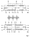
- Fig. 1 an elongated extended normally-latch 10 is shown, which with a Closing pattern 20 is provided, seen to the narrow axis 11, a has asymmetrical shape.
- connection elements 13 for a connection 25 provided with those of the closer-latch 10 by 180 ° umtschbar a fitting shown later 30 by positive engagement by hacking or plugging is connectable.
- a lock pin 31 which at one, with the fitting 30th pivotally connected extension arm 32 is attached. It is the Functional situation each marked with letters, namely: closing V, tilt K, rotate D, with the top row of letters the first Installation position (DK) and the lower row refer to the second installation position (TBT).
- the closing pattern 20 of the closer bolt 10 is as such by each opposite longitudinally arranged boundary cheeks 14 embodied, which form a guide 15.
- the boundary cheeks 14 are penetrated by openings 16, which are provided with chamfers 17.
- the locking positions V and turn D locking Locking pin 31 can through the apertures 16 from the guide 15th emerge when the closer latch 10 the according to his chosen Installation position given position tilting K occupies, i. in the shown Embodiment is, as indicated in Fig. 1 by the arrows, the Normally open latch 10 is moved by fitting 30, wherein the locking pin 31 when entering or exiting in or out of the guide 15 by the Breakthrough 16 during the tilting of the wing one - accordingly the interpretation of the extension arm 32 - describes approximately straight path. Due to the storage of Ausstellarmes 32 to a not shown Frame fixes this fixed the position of the wing.
- the closer latch 10 is in the second Installation position for the tilt-turn sequence (TBT) turned by 180 ° shown arranged.
- TBT tilt-turn sequence
- the Locking pin 31 of the limiting cheeks 14 within the left part the guide 15 held positively. If the closer-bar 10 after shifted left, the locking pin 31 immediately enters the area of Breakthroughs 16 and the wing can be tilted into the tilting position, as the locking pin 31 no longer from the Begrenzungswangen 14 in the Guide 15 is held. To turn the wing, this is from the Tilted tipping back, whereby the locking pin 31 through the Breakthroughs 16 again enters the guide 15.
- the closer latch 10 is pushed further to the left by means of the fitting 30, wherein the Chamfers 17 a safe opening of the lock pin 31 in the Leadership 15 effect.
- the locking pin 31 enters the - based on the closing pattern 20 seen - right-lying portion of the guide 15, in which the locking pin 31 positively between the Limiting cheeks 14 is held in the position turning D and thus the Wing can be safely turned.
- a bump 27th is arranged, which together with the opening 26 of the closer latch 10th form a positive connection connection 25.
- the NO bolt 10 during assembly according to the desired Function sequence Turn-tilt (DK) according to Fig. 2 or tilt-turn (TBT) According to Fig. 3 via the connection connection 25 can be coupled.
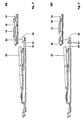
- FIGS. 6 and 7 show the positions of a switching element in the form of a Levers 40, with the fitting 30 in these sliding Active connection stands and the function sequences according to the two Installation positions of the closer bolt 10 sets, where V for closing, D for turning and K for tilting the sash stands.
- Fig. 6 shows the sequence of the first Installation position of the NO bolt 10 - Locked, turn, then tilt (DK) - and
- Fig. 7 shows the second installation position - locked, tilting then turning (TBT).
- the closed position V embodies a downward in both cases directed lever 40.
- the closer-latch 10 is depending on the sash weight as a die-cast molding or as a precision forging molding rationally manufactured and used.
Landscapes
- Engineering & Computer Science (AREA)
- Mechanical Engineering (AREA)
- Lock And Its Accessories (AREA)
- Closing And Opening Devices For Wings, And Checks For Wings (AREA)
- Pallets (AREA)
- Holders For Apparel And Elements Relating To Apparel (AREA)
- Toilet Supplies (AREA)
Description
Vorzugsweise sind an den Begrenzungswandungen wenigstens im Bereich der Durchbrüche Anlaufschrägen vorgesehen, welche das Eingreifen des Schließzapfens im Einbauzustand begünstigen, wenn der Schließzapfen wieder in die Führung eintritt und eine weitere Stellung des Schießer-Riegels über den Beschlag durch Verschieben bewirkt wird.
- Fig. 1
- eine vergrößerte Ansicht von oben auf einen Schließer-Riegel gemäß der Erfindung in einer ersten Einbaulage (DK) und einer zweiten Einbaulage (TBT),
- Fig. 2
- eine isometrische Ansicht des erfindungsgemäßen Schließer-Riegels gemäß Fig. 1 in der ersten Einbaulage (DK) vor dem Ankoppeln an einen Beschlag,
- Fig. 3
- eine isometrische Ansicht des erfindungsgemäßen Schließer-Riegels gemäß Fig. 1 in der zweiten Einbaulage (TBT) vor dem Ankoppeln an den Beschlag,
- Fig. 4
- die erste Einbaulage (DK) des Schließer-Riegels gemäß Fig. 1 mit angekoppeltem Beschlag,
- Fig. 5
- die zweite Einbaulage (TBT) des Schließer-Riegels gemäß Fig. 1 mit angekoppeltem Beschlag,
- Fig. 6
- eine Darstellung der Hebelstellungen für den Schließer-Riegel in der ersten Einbaulage (DK) und
- Fig. 7
- eine Darstellung der Hebelstellungen für den Schließer-Riegel in der zweiten Einbaulage (TBT).
- 10
- Schließer-Riegel
- 11
- Vertikalachse
- 12
- Enden der Langseite
- 13
- Anschlußelemente
- 14
- Begrenzungswangen
- 15
- Führung
- 16
- Durchbrüche
- 17
- Anlaufschrägen
- 20
- Schließmuster
- 25
- Anschlußverbindung
- 26
- Öffnung
- 27
- Höcker
- 30
- Beschlag
- 31
- Schließzapfen
- 32
- Ausstellarm
- 35
- Lager
- 40
- Schaltglied (Hebel)
- DK
- Drehen vor Kippen
- TBT
- Tilt before turn (Kippen vor Drehen)
- V
- Verschließen
- D
- Drehen
- K
- Kippen
Claims (10)
- Schließer-Riegel für dreh- und kippbare Fenster und/oder Türen, bei denen die gewünschte Schaltfolge von einem betätigbaren Schaltglied (Hebel) mittels wenigstens einem Beschlag bewirkbar ist,
dadurch gekennzeichnet, daß der Schließer-Riegel (10) sowohl das Schließmuster (20) der Dreh-Kipp- (DK) als auch das der Kipp-Dreh- Schaltfolge (TBT) aufweist, wobei das Schließmuster (20) derart angeordnet ist, daß der Schließer-Riegel (10) in der einen Einbaulage an dem Beschlag (30) die Dreh-Kipp-Schaltfolge (DK) und in der anderen, um 180° umschlagbaren Einbaulage die Kipp-Dreh-Schaltfolge (TBT) bewirkt. - Schließer-Riegel nach Anspruch 1,
dadurch gekennzeichnet, daß der Schließer-Riegel (10) mit einem, die Kipplage des Flügels festlegenden Ausstellarm (32) zusammenwirkt, der die Schaltstellung (V, D, K; V, K, D) festlegt. - Schließer-Riegel nach Anspruch 1 oder 2,
dadurch gekennzeichnet, daß das Schließmuster (20) auf dem Schließer-Riegel (10) zur Vertikalachse (11) gesehen asymmetrische Form aufweist und vorzugsweise jeweils an den Enden der Langseite Anschlußelemente (13) für eine Anschlußverbindung (25) aufweist, mit denen der Schließer-Riegel (10) um 180° umschlagbar an den Beschlag (30) vorzugsweise mittels Formschluss anschließbar ist. - Schließer-Riegel nach Anspruch 3,
dadurch gekennzeichnet, daß die Anschlußverbindung (25) von dem Beschlag (30) und dem Schließer-Riegel (10) als steck- oder verhakbare Verbindung ausgebildet ist. - Schließer-Riegel nach Anspruch 3 oder 4,
dadurch gekennzeichnet, daß das Anschlußelement (13) auf Seiten des Schließer-Riegels (10) auf jeder Seite als Öffnung (26) ausgebildet ist, in die wenigstens ein an dem Beschlag (30) angeformter Höcker (27) formschlüssig eingreift. - Schließer-Riegel nach Anspruch 3 oder 4,
dadurch gekennzeichnet, daß das Anschlußelement (13) auf Seiten des Beschlages (30) wenigstens eine Öffnung (26) aufweist, in das wenigstens ein an dem Schließer-Riegel (10) angeformter Höcker (27) formschlüssig eingreift. - Schließer-Regler nach Anspruch 1 bis 6,
dadurch gekennzeichnet, daß das Schließmuster (20) des Schließer-Riegels (10) durch längsseitig angeordnete Begrenzungswangen (14) verkörpert ist, die eine Führung (15) formen, wobei die Begrenzungswangen (14) Durchbrüche (16) aufweisen, durch die ein, die Schaltstellung Verschließen (V) und Drehen (D) sichernder Schließzapfen (31) austreten kann, wenn der Schließer-Riegel (10) in die Schaltstellung Kippen (K) überführt ist und diese gegenüberliegend zur Längsseite gesehen asymmetrisch angeordnete Durchbrüche (16) den Teil des Schließmuster (20) darstellen, der beim Umschlagen des Schließer-Riegels (10) um 180° an dem Beschlag (30) zwecks wahlweiser Schaltfolgen-Festlegung wirksam wird: Verschließen - Drehen - Kippen (DK) oder Verschließen - Kippen - Drehen (TBT). - Schließer-Regler nach Anspruch 7
dadurch gekennzeichnet, daß an den Begrerizungswangen (14) wenigstens im Bereich der Durchbrüche (16) Anlaufschrägen (17) vorgesehen sind zwecks Sicherung der Einlaufsicherheit des Schließerzapfens (31) in die Führung (15). - Schließer-Riegel nach einem der Ansprüche 1 bis 8,
dadurch gekennzeichnet, daß der Schließer-Riegel (10) als Druckguß-Formteil herstellbar ist. - Schließer-Riegel nach einem der Ansprüche 1 bis 8,
dadurch gekennzeichnet, daß der Schließer-Riegel (10) als Präzisions-Schmiede-Formteil herstellbar ist.
Applications Claiming Priority (3)
| Application Number | Priority Date | Filing Date | Title |
|---|---|---|---|
| DE10028196A DE10028196A1 (de) | 2000-06-09 | 2000-06-09 | Schließer-Riegel für dreh-und kippbare Fenster und/oder Türen |
| DE10028196 | 2000-06-09 | ||
| PCT/EP2001/003217 WO2001094729A1 (de) | 2000-06-09 | 2001-03-21 | Schliesser-riegel für dreh- und kippbare fenster und/oder türen |
Publications (2)
| Publication Number | Publication Date |
|---|---|
| EP1290302A1 EP1290302A1 (de) | 2003-03-12 |
| EP1290302B1 true EP1290302B1 (de) | 2005-07-27 |
Family
ID=7644999
Family Applications (1)
| Application Number | Title | Priority Date | Filing Date |
|---|---|---|---|
| EP01915391A Expired - Lifetime EP1290302B1 (de) | 2000-06-09 | 2001-03-21 | Schliesser-riegel für dreh- und kippbare fenster und/oder türen |
Country Status (6)
| Country | Link |
|---|---|
| EP (1) | EP1290302B1 (de) |
| AT (1) | ATE300648T1 (de) |
| AU (1) | AU2001242494A1 (de) |
| DE (2) | DE10028196A1 (de) |
| ES (1) | ES2245353T3 (de) |
| WO (1) | WO2001094729A1 (de) |
Families Citing this family (2)
| Publication number | Priority date | Publication date | Assignee | Title |
|---|---|---|---|---|
| BE1017949A5 (nl) * | 2008-01-17 | 2010-01-12 | Parys Remi E Van | Beslag van een raam en onderdelen daarvoor. |
| EP4644649A1 (de) * | 2024-05-03 | 2025-11-05 | Masterlab S.R.L. | Zubehör für drehkipptüren oder -fenster |
Family Cites Families (4)
| Publication number | Priority date | Publication date | Assignee | Title |
|---|---|---|---|---|
| DE8500746U1 (de) * | 1985-01-15 | 1985-06-05 | August Bilstein GmbH & Co KG, 5828 Ennepetal | Treibstangenbeschlag für Dreh-Kipp-Fenster od. dgl. mit Schaltsperre |
| GB2175631B (en) * | 1985-05-24 | 1988-07-13 | Hardware & Systems Patents Ltd | Window |
| DE3617216A1 (de) * | 1986-05-22 | 1987-11-26 | Siegenia Frank Kg | Ausstellvorrichtung fuer kippfluegel, insbesondere drehkipp- oder auch schiebekippfluegel, von fenstern, tueren od. dgl. |
| DE9002735U1 (de) * | 1990-03-08 | 1991-07-04 | Siegenia-Frank Kg, 5900 Siegen | Beschlag für Fenster, Türen. od.dgl. |
-
2000
- 2000-06-09 DE DE10028196A patent/DE10028196A1/de not_active Withdrawn
-
2001
- 2001-03-21 DE DE50106907T patent/DE50106907D1/de not_active Expired - Lifetime
- 2001-03-21 WO PCT/EP2001/003217 patent/WO2001094729A1/de not_active Ceased
- 2001-03-21 ES ES01915391T patent/ES2245353T3/es not_active Expired - Lifetime
- 2001-03-21 AT AT01915391T patent/ATE300648T1/de not_active IP Right Cessation
- 2001-03-21 EP EP01915391A patent/EP1290302B1/de not_active Expired - Lifetime
- 2001-03-21 AU AU2001242494A patent/AU2001242494A1/en not_active Abandoned
Also Published As
| Publication number | Publication date |
|---|---|
| EP1290302A1 (de) | 2003-03-12 |
| DE10028196A1 (de) | 2002-01-31 |
| AU2001242494A1 (en) | 2001-12-17 |
| DE50106907D1 (de) | 2005-09-01 |
| WO2001094729A1 (de) | 2001-12-13 |
| ATE300648T1 (de) | 2005-08-15 |
| ES2245353T3 (es) | 2006-01-01 |
Similar Documents
| Publication | Publication Date | Title |
|---|---|---|
| EP1959080B1 (de) | Beschlag für einen Schiebeflügel von Fenster oder Tür | |
| DE2920581C3 (de) | Zusatzverriegelung, insbesondere Mittelverriegelung, für Fenster, Türen od.dgl. | |
| EP3363976B1 (de) | Drehöffnungsbegrenzungsanordnung für ein fenster oder eine tür zur begrenzung der drehöffnungsbewegung eines flügels eines fensters oder einer tür | |
| EP2058461B1 (de) | Treibstangengetriebe | |
| DE10134249A1 (de) | Verriegelungsbeschlag mit drehbarer Riegelleiste | |
| DE19511929C1 (de) | Dreh- und/oder Kipp-Beschlag für Fenster, Türen od. dgl. mit einem zwischen dem Flügel und dem Rahmen angeordneten Flügelheber | |
| DE3022163C2 (de) | Dreh-Kipp-Beschlag für Fenster, Türen o.dgl. mit Spaltlüftung | |
| DE10147782A1 (de) | Betätigungsgetriebe, insbesondere Schloss für einen Treibstangenbeschlag sowie Treibstangenbeschlag mit einem solchen Betätigungsgetriebe | |
| DE2658626B2 (de) | Schaltsperre für Treibstangenbeschläge | |
| DE3221110C2 (de) | ||
| EP1008713A1 (de) | Verriegelungsvorrichtung | |
| EP1290302A1 (de) | Schliesser-riegel für dreh- und kippbare fenster und/oder türen | |
| EP1614844A2 (de) | Drehlagervorrichtung | |
| EP2453086B1 (de) | Treibstangenbeschlag für Standflügel von zweiflügeligen Fenstern oder Türen ohne Mittelpfosten | |
| EP1405973B1 (de) | Beschlagmechanik für ein Drehkippfenster oder eine Drehkipptüre | |
| EP1309767B1 (de) | Dreh-kipp-beschlag für fenster, türen od. dgl. | |
| EP0367842B1 (de) | Handhebelgetriebe zum Aufschrauben auf den Flügelrahmen von Fenstern, Türen oder dergleichen | |
| EP0356772B1 (de) | Treibstangenschloss | |
| DE102014226794A1 (de) | Beschlag zum Einbau zwischen einem Flügel und einem festen Rahmen eines Fensters, einer Tür oder dergleichen sowie Fenster, Tür oder dergleichen mit einem derartigen Beschlag | |
| EP4174264B1 (de) | Flügelanordnung | |
| EP2103770B1 (de) | Beschlaganordnung | |
| AT375724B (de) | Vorrichtung zur selbsttaetigen fehlbedienungssicherung von kipp-schwenk-fluegeln an fenstern, tueren od.dgl. | |
| EP1421245B1 (de) | Fehlbedienungssicherung für treibstangenbeschläge | |
| DE102007035123A1 (de) | Kippsicherung | |
| EP0732475A1 (de) | Beschlag für Fenster, Türen oder dergleichen |
Legal Events
| Date | Code | Title | Description |
|---|---|---|---|
| PUAI | Public reference made under article 153(3) epc to a published international application that has entered the european phase |
Free format text: ORIGINAL CODE: 0009012 |
|
| 17P | Request for examination filed |
Effective date: 20020704 |
|
| AK | Designated contracting states |
Designated state(s): AT BE CH CY DE DK ES FI FR GB GR IE IT LI LU MC NL PT SE TR Kind code of ref document: A1 Designated state(s): AT BE CH CY DE DK ES FI FR GB GR IE IT LI LU MC NL PT SE TR |
|
| AX | Request for extension of the european patent |
Extension state: AL LT LV MK RO SI |
|
| RAP1 | Party data changed (applicant data changed or rights of an application transferred) |
Owner name: SIEGENIA-AUBI KG |
|
| RAP1 | Party data changed (applicant data changed or rights of an application transferred) |
Owner name: SIEGENIA-AUBI KG |
|
| RAP1 | Party data changed (applicant data changed or rights of an application transferred) |
Owner name: SIEGENIA-AUBI KG |
|
| GRAP | Despatch of communication of intention to grant a patent |
Free format text: ORIGINAL CODE: EPIDOSNIGR1 |
|
| GRAS | Grant fee paid |
Free format text: ORIGINAL CODE: EPIDOSNIGR3 |
|
| GRAA | (expected) grant |
Free format text: ORIGINAL CODE: 0009210 |
|
| AK | Designated contracting states |
Kind code of ref document: B1 Designated state(s): AT BE CH CY DE DK ES FI FR GB GR IE IT LI LU MC NL PT SE TR |
|
| PG25 | Lapsed in a contracting state [announced via postgrant information from national office to epo] |
Ref country code: TR Free format text: LAPSE BECAUSE OF FAILURE TO SUBMIT A TRANSLATION OF THE DESCRIPTION OR TO PAY THE FEE WITHIN THE PRESCRIBED TIME-LIMIT Effective date: 20050727 Ref country code: FI Free format text: LAPSE BECAUSE OF FAILURE TO SUBMIT A TRANSLATION OF THE DESCRIPTION OR TO PAY THE FEE WITHIN THE PRESCRIBED TIME-LIMIT Effective date: 20050727 Ref country code: IE Free format text: LAPSE BECAUSE OF FAILURE TO SUBMIT A TRANSLATION OF THE DESCRIPTION OR TO PAY THE FEE WITHIN THE PRESCRIBED TIME-LIMIT Effective date: 20050727 Ref country code: NL Free format text: LAPSE BECAUSE OF FAILURE TO SUBMIT A TRANSLATION OF THE DESCRIPTION OR TO PAY THE FEE WITHIN THE PRESCRIBED TIME-LIMIT Effective date: 20050727 |
|
| REG | Reference to a national code |
Ref country code: GB Ref legal event code: FG4D Free format text: NOT ENGLISH |
|
| REG | Reference to a national code |
Ref country code: CH Ref legal event code: EP |
|
| GBT | Gb: translation of ep patent filed (gb section 77(6)(a)/1977) |
Effective date: 20050727 |
|
| REG | Reference to a national code |
Ref country code: IE Ref legal event code: FG4D Free format text: LANGUAGE OF EP DOCUMENT: GERMAN |
|
| REF | Corresponds to: |
Ref document number: 50106907 Country of ref document: DE Date of ref document: 20050901 Kind code of ref document: P |
|
| PG25 | Lapsed in a contracting state [announced via postgrant information from national office to epo] |
Ref country code: SE Free format text: LAPSE BECAUSE OF FAILURE TO SUBMIT A TRANSLATION OF THE DESCRIPTION OR TO PAY THE FEE WITHIN THE PRESCRIBED TIME-LIMIT Effective date: 20051027 Ref country code: GR Free format text: LAPSE BECAUSE OF FAILURE TO SUBMIT A TRANSLATION OF THE DESCRIPTION OR TO PAY THE FEE WITHIN THE PRESCRIBED TIME-LIMIT Effective date: 20051027 Ref country code: DK Free format text: LAPSE BECAUSE OF FAILURE TO SUBMIT A TRANSLATION OF THE DESCRIPTION OR TO PAY THE FEE WITHIN THE PRESCRIBED TIME-LIMIT Effective date: 20051027 |
|
| PG25 | Lapsed in a contracting state [announced via postgrant information from national office to epo] |
Ref country code: PT Free format text: LAPSE BECAUSE OF FAILURE TO SUBMIT A TRANSLATION OF THE DESCRIPTION OR TO PAY THE FEE WITHIN THE PRESCRIBED TIME-LIMIT Effective date: 20051227 |
|
| REG | Reference to a national code |
Ref country code: ES Ref legal event code: FG2A Ref document number: 2245353 Country of ref document: ES Kind code of ref document: T3 |
|
| NLV1 | Nl: lapsed or annulled due to failure to fulfill the requirements of art. 29p and 29m of the patents act | ||
| REG | Reference to a national code |
Ref country code: IE Ref legal event code: FD4D |
|
| PG25 | Lapsed in a contracting state [announced via postgrant information from national office to epo] |
Ref country code: AT Free format text: LAPSE BECAUSE OF NON-PAYMENT OF DUE FEES Effective date: 20060321 |
|
| ET | Fr: translation filed | ||
| PG25 | Lapsed in a contracting state [announced via postgrant information from national office to epo] |
Ref country code: LI Free format text: LAPSE BECAUSE OF NON-PAYMENT OF DUE FEES Effective date: 20060331 Ref country code: LU Free format text: LAPSE BECAUSE OF NON-PAYMENT OF DUE FEES Effective date: 20060331 Ref country code: MC Free format text: LAPSE BECAUSE OF NON-PAYMENT OF DUE FEES Effective date: 20060331 Ref country code: CH Free format text: LAPSE BECAUSE OF NON-PAYMENT OF DUE FEES Effective date: 20060331 |
|
| PLBE | No opposition filed within time limit |
Free format text: ORIGINAL CODE: 0009261 |
|
| STAA | Information on the status of an ep patent application or granted ep patent |
Free format text: STATUS: NO OPPOSITION FILED WITHIN TIME LIMIT |
|
| 26N | No opposition filed |
Effective date: 20060428 |
|
| REG | Reference to a national code |
Ref country code: CH Ref legal event code: PL |
|
| PG25 | Lapsed in a contracting state [announced via postgrant information from national office to epo] |
Ref country code: CY Free format text: LAPSE BECAUSE OF FAILURE TO SUBMIT A TRANSLATION OF THE DESCRIPTION OR TO PAY THE FEE WITHIN THE PRESCRIBED TIME-LIMIT Effective date: 20050727 |
|
| PGFP | Annual fee paid to national office [announced via postgrant information from national office to epo] |
Ref country code: GB Payment date: 20090324 Year of fee payment: 9 |
|
| GBPC | Gb: european patent ceased through non-payment of renewal fee |
Effective date: 20100321 |
|
| PG25 | Lapsed in a contracting state [announced via postgrant information from national office to epo] |
Ref country code: GB Free format text: LAPSE BECAUSE OF NON-PAYMENT OF DUE FEES Effective date: 20100321 |
|
| PGFP | Annual fee paid to national office [announced via postgrant information from national office to epo] |
Ref country code: FR Payment date: 20110401 Year of fee payment: 11 |
|
| PGFP | Annual fee paid to national office [announced via postgrant information from national office to epo] |
Ref country code: ES Payment date: 20110323 Year of fee payment: 11 |
|
| REG | Reference to a national code |
Ref country code: FR Ref legal event code: ST Effective date: 20121130 |
|
| PG25 | Lapsed in a contracting state [announced via postgrant information from national office to epo] |
Ref country code: FR Free format text: LAPSE BECAUSE OF NON-PAYMENT OF DUE FEES Effective date: 20120402 |
|
| REG | Reference to a national code |
Ref country code: ES Ref legal event code: FD2A Effective date: 20130710 |
|
| PG25 | Lapsed in a contracting state [announced via postgrant information from national office to epo] |
Ref country code: ES Free format text: LAPSE BECAUSE OF NON-PAYMENT OF DUE FEES Effective date: 20120322 |
|
| PGFP | Annual fee paid to national office [announced via postgrant information from national office to epo] |
Ref country code: BE Payment date: 20170220 Year of fee payment: 17 |
|
| PGFP | Annual fee paid to national office [announced via postgrant information from national office to epo] |
Ref country code: IT Payment date: 20170331 Year of fee payment: 17 |
|
| PGFP | Annual fee paid to national office [announced via postgrant information from national office to epo] |
Ref country code: DE Payment date: 20170331 Year of fee payment: 17 |
|
| REG | Reference to a national code |
Ref country code: DE Ref legal event code: R119 Ref document number: 50106907 Country of ref document: DE |
|
| REG | Reference to a national code |
Ref country code: BE Ref legal event code: MM Effective date: 20180331 |
|
| PG25 | Lapsed in a contracting state [announced via postgrant information from national office to epo] |
Ref country code: DE Free format text: LAPSE BECAUSE OF NON-PAYMENT OF DUE FEES Effective date: 20181002 |
|
| PG25 | Lapsed in a contracting state [announced via postgrant information from national office to epo] |
Ref country code: BE Free format text: LAPSE BECAUSE OF NON-PAYMENT OF DUE FEES Effective date: 20180331 Ref country code: IT Free format text: LAPSE BECAUSE OF NON-PAYMENT OF DUE FEES Effective date: 20180321 |