EP1290767B1 - Vorrichtung zur umhüllung eines elements einer drahtleitung - Google Patents
Vorrichtung zur umhüllung eines elements einer drahtleitung Download PDFInfo
- Publication number
- EP1290767B1 EP1290767B1 EP20010936575 EP01936575A EP1290767B1 EP 1290767 B1 EP1290767 B1 EP 1290767B1 EP 20010936575 EP20010936575 EP 20010936575 EP 01936575 A EP01936575 A EP 01936575A EP 1290767 B1 EP1290767 B1 EP 1290767B1
- Authority
- EP
- European Patent Office
- Prior art keywords
- stuffing
- shell
- shells
- boxes
- box
- Prior art date
- Legal status (The legal status is an assumption and is not a legal conclusion. Google has not performed a legal analysis and makes no representation as to the accuracy of the status listed.)
- Expired - Lifetime
Links
- 238000012856 packing Methods 0.000 claims abstract description 8
- 230000008878 coupling Effects 0.000 claims description 4
- 238000010168 coupling process Methods 0.000 claims description 4
- 238000005859 coupling reaction Methods 0.000 claims description 4
- 238000000605 extraction Methods 0.000 claims description 3
- 239000012780 transparent material Substances 0.000 claims 1
- 238000007789 sealing Methods 0.000 abstract description 6
- 235000005921 Cynara humilis Nutrition 0.000 description 5
- 240000002228 Cynara humilis Species 0.000 description 5
- 238000010586 diagram Methods 0.000 description 4
- 239000000835 fiber Substances 0.000 description 2
- 206010001488 Aggression Diseases 0.000 description 1
- 239000002253 acid Substances 0.000 description 1
- 230000004913 activation Effects 0.000 description 1
- 230000016571 aggressive behavior Effects 0.000 description 1
- 230000006835 compression Effects 0.000 description 1
- 238000007906 compression Methods 0.000 description 1
- 210000005069 ears Anatomy 0.000 description 1
- 230000005611 electricity Effects 0.000 description 1
- 230000001815 facial effect Effects 0.000 description 1
- 238000009413 insulation Methods 0.000 description 1
- 239000000463 material Substances 0.000 description 1
- 244000045947 parasite Species 0.000 description 1
- 238000005192 partition Methods 0.000 description 1
- 230000000149 penetrating effect Effects 0.000 description 1
- 230000002093 peripheral effect Effects 0.000 description 1
- 229920003023 plastic Polymers 0.000 description 1
- 239000004576 sand Substances 0.000 description 1
- XLYOFNOQVPJJNP-UHFFFAOYSA-N water Substances O XLYOFNOQVPJJNP-UHFFFAOYSA-N 0.000 description 1
Images


Classifications
-
- H—ELECTRICITY
- H02—GENERATION; CONVERSION OR DISTRIBUTION OF ELECTRIC POWER
- H02G—INSTALLATION OF ELECTRIC CABLES OR LINES, OR OF COMBINED OPTICAL AND ELECTRIC CABLES OR LINES
- H02G15/00—Cable fittings
- H02G15/08—Cable junctions
- H02G15/10—Cable junctions protected by boxes, e.g. by distribution, connection or junction boxes
- H02G15/115—Boxes split perpendicularly to main cable direction
-
- H—ELECTRICITY
- H02—GENERATION; CONVERSION OR DISTRIBUTION OF ELECTRIC POWER
- H02G—INSTALLATION OF ELECTRIC CABLES OR LINES, OR OF COMBINED OPTICAL AND ELECTRIC CABLES OR LINES
- H02G15/00—Cable fittings
- H02G15/007—Devices for relieving mechanical stress
Definitions
- the present invention relates to a device wrapping for wire line element. She finds a particularly interesting application but not exclusively in the field of electricity for which one wishes to protect, as an element, a connection between two electric wires or cables constituting a typical example for said wire line. But this can also consist of a connection telephone, fiber optic, TV antenna, information network etc.
- the document WO 98/00888 describes a device for cable connection protection in the form of a straight transparent tube which can be opened according to the longitudinal to insert a cable connection.
- An object of the invention is to provide protection waterproof and / or insulating and / or mechanical of the element line, for example a connection.
- Another object of the invention is to provide a device simple and quick to handle.
- Another object of the invention is to provide a effective device adaptable to many genres line elements to protect and / or secure.
- a partial shell carries a seal seal intended to come into contact with each other partial shell during axial tightening.
- This joint seal may be an O-ring disposed near the no screw of a partial shell.
- the stuffing boxes can be made of bell-shaped, each substantially covering the face interior of one of the partial hulls. So the stuffing boxes are very rigid and transmit effectively their force of mutual support to the linings respectively.
- the tightening is done by mutual axial rotation of the two partial shells.
- the device comprises means for coupling to immobilize the two stuffing boxes in rotation relative to each other.
- the coupling means can advantageously comprise teeth provided on the stuffing boxes at their ends turned towards each other.
- the teeth of each stuffing box are intended to be engaged with those of the other stuffing box.
- the teeth are preferably in the shape of a sawtooth to facilitate interpenetration in any position relative angular departure.
- a first of the stuffing boxes can be immobilized in axial rotation with respect to a first, corresponding, of the two partial shells. If both stuffing boxes are, at least at the end of tightening, integral in rotation with one another, they form a everything with the first partial hull, the wires and the element, and for tightening only the other shell partial will rotate with respect to this whole.
- the aforementioned immobilization in rotation of the first stuffing box can be obtained by means of minus an eccentric projecting element integral with the shell partial corresponding and engaging in at least one recess of the first stuffing box. This element protruding can be shaped as a hook limiting the extraction movement of the first stuffing box by compared to the corresponding partial hull.
- the device includes means restraint limiting the axial extraction movement of each stuffing box relative to the partial shell corresponding by retaining the captive trim substantially in its service position around the orifice. And these restraints can be snap-in means.
- the retaining means include hooks integral with the partial shells and engaging behind shoulders formed on the stuffing boxes.
- the device according to the invention achieves, preferably continuous insulation from wire to wire around the element for the medium conveyed by the line, vis-à-vis the surrounding environment around the hull.
- each stuffing box in the corresponding partial shell. This avoids, by example, that the teeth arranged on the ends of each stuffing box overlap instead of being in facial contact.
- the stuffing box correspondent are shaped so as to collect two wire lines through two separate holes.
- the corresponding stuffing box includes a spreader to distribute the compression forces applied to each seal fitted around each hole.
- the fittings sealing arranged in the partial shell having two orifices may have a hardness lower than that of the seal fitted in the other shell partial showing only one orifice. We equalize thus the deformations undergone by all of the linings the device.
- the device according to the invention can be made of transparent plastic to make visible the electrical assembly located inside the device.
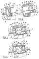
- the device 1 comprises a shell composed of two partial shells 5 and 6 in the form of bell and intended to engage with each other by screwing by means of the threads 11 and 12 provided on along their respective open edges.
- Figures 1 and 4 show the device 1 in open configuration, the shells parts 5 and 6 are detached and arranged respectively on wires 2 and 3 facing each other to each other.
- the domino 4 is placed between the shells wires 5 and 6 while wires 2 and 3 go to through orifices 21 and 22 produced substantially at center of the bottoms of the two partial shells.
- the device further comprises in each partial shell 5 or 6 a respective stuffing box 7 or 8 arranged at the interior of the corresponding partial hull and having for the role of applying a pressure force on a respective annular seal 9 or 10 placed around hole 21 or 22.
- the stuffing boxes 7 and 8 are also bell-shaped, the bottom is crossed by a central orifice for the wire passage.
- the seals 9 and 10 are rings of elastically deformable material which bear radially against wire 2 or 3 when the stuffing box 7 or 8 sinks into the partial shell respectively.
- the orifice of each stuffing box is equipped with a bore 41 flared towards the bottom corresponding bell.
- This depression of the stuffing boxes 7 and 8 is due to mutual support of the two stuffing boxes by their open edge 24, 25 when screw the partial shells 5 and 6 with each other according to Figures 2, 3, 5 and 6.
- the linings 9 and 10 do not exercise significant pressing force on wires 2 and 3 before mutual tightening of the partial shells.
- the ends open 24, 25 of packing seals 7 and 8 are in sawtooth shape 24 and 25. So during the step illustrated in Figure 5, when performing the screwing the partial shells 5 and 6, these sawtooth keep the two stuffing boxes stationary in rotation relative to each other.
- two stuffing boxes are made stationary in rotation relative to the partial hull 6 by means of three eccentric projecting elements 17 integral with the bottom of the partial shell 6 and penetrating into recesses made through the bottom of stuffing box 8 corresponding.
- the screwing is obtained by rotation of the partial hull 5 relative to the assembly including stuffing boxes 7, 8, partial shell 6, the two wires 2 and 3 and the domino.
- circular flanges 13, 14 and 15 are arranged on the outer sides of the stuffing boxes 7 and 8 for centering against the face inner peripheral of the partial shells.
- the projecting elements 17 each have a hook 18 capable of pressing against the face inside, forming a shoulder, from the bottom of the stuffing box 8, in order to keep the stuffing box 8 in the partial shell 6 when the partial shells are separated ( Figures 1 and 4).
- the stuffing box 7 is held in the partial shell 5 by means of a hook 19 shaped on a projecting element 16 integral with the partial shell 5. This projecting element 16 is placed at the outside of the stuffing box 7 and does not immobilize in rotation of the stuffing box 7.
- the hooks 18, 19 have ramps engagement 26 for mounting each stuffing box 7 or 8 by simply snapping into the hull partial corresponding.
- the hooks are arranged on the elements projections 16, 17 so that the stuffing boxes have an axial translation movement margin on these salient elements with respect to the shells partial 5, 6 to release the linings 9, 10 all holding them in place around the holes when the partial shells are separated, and compress the fittings when the partial shells are tight.
- the assembly formed by the stuffing boxes 7 and 8 shifts towards the wire of smaller diameter when the partial shells 5 and 6 are fixed one to the other. Packings 7 and 8 therefore have the ability to self-balance in order to exert a force of almost identical pressure on the two linings sealing 9 and 10.
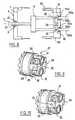
- the mode of implementation of the invention illustrated on Figure 7 will only be described for its differences by compared to that of FIGS. 4 to 6.
- the partial shell 34 corresponds to partial shell 6, except that it carries a flange 29 on which are arranged screws 30, 31 and 32 intended to fix this partial shell 34 on a wall that the line must cross.
- the wall can be a building partition, a boat deck.
- a joint can be placed under the flange 29 for contact with the wall.
- a partial shell 35 forms a device identical to the partial shell 5 described with reference to Figures 1 to 6, except shape 28 of the outer contour, intended to facilitate handling for the locking of this shell 35 on the partial shell fixed 34.
- the dimensions of the partial shells 34 and 35 are such that they may contain a plug electric, large compared to the domino 4, connecting wires 2 and 3.
- the present invention therefore makes it possible to protect from tightly and rigidify by a rigid shell a connection between two cables or more generally one element on a wire line.
- the handling is simple and the size of the device according to the invention can be adapted to the type of connection made.
- Figure 8 is a diagram illustrating a variant of the invention in which one wishes to connect two lines wired 103a and 103b to wired line 2 using the domino 4. In particular, we will describe the differences of this figure 8 compared to figure 1.
- the shell partial 106 includes two orifices 122a and 122b around which are arranged two seals 110a and 110b.
- the stuffing box 33 is equipped with a lifter provided with two support rings 31 and 32 each suitable for compress the respective one of the seals 110a and 110b.
- spreader 27 swivels slightly around the axis 29 by pushing the ring further of support through which the wired line passes more small diameter.
- Means preventing rotation of stuffing boxes between them and / or in relation to one of the hulls are not essential, especially if the partial shells are tightened on a fraction of turn.
- the means preventing rotation can operate by friction instead of locking.
Landscapes
- Installation Of Indoor Wiring (AREA)
- Control Of Vending Devices And Auxiliary Devices For Vending Devices (AREA)
- Internal Circuitry In Semiconductor Integrated Circuit Devices (AREA)
- Insulation, Fastening Of Motor, Generator Windings (AREA)
- Road Signs Or Road Markings (AREA)
- Microwave Amplifiers (AREA)
- Ropes Or Cables (AREA)
- Prostheses (AREA)
- Electrical Discharge Machining, Electrochemical Machining, And Combined Machining (AREA)
Claims (15)
- Umhüllungsvorrichtung für ein Element (4) einer Drahtleitung (2, 3), umfassend:dadurch gekennzeichnet, daß die Stopfbuchsen (7, 8) mit Mitteln (24, 25) zur mindestens indirekten gegenseitigen Anlage versehen sind, so daß das axiale Anziehen der Teilschalen (5, 6) nach gegenseitiger Anlage der Stopfbuchsen ein radiales Anpressen der Dichtungen (9, 10) an die Drahtleitung und gleichzeitig ein axiales Anpressen der Dichtungen (9, 10) an die Böden der Teilschalen (5, 6) bewirkt, so daß die Öffnungen (21, 22) abgedichtet werden; und daß die Kammer dadurch abgedichtet wird, daß eine der Teilschalen (5) einen Dichtring (20) trägt, der dazu bestimmt ist, bei dem axialen Anziehen mit der anderen Teilschale (6) in Kontakt zu kommen.eine Schale, die in ihrem Inneren eine Kammer zur Aufnahme des Elements begrenzt und mindestens teilweise aus zwei Teilschalen (5, 6) besteht, die durch axiales Anziehen aneinander befestigt werden können und jeweils eine Öffnung (21, 22) zum Durchgang des Drahts besitzen;eine Dichtung (9, 10) um jede Öffnung herum;zwei im Inneren der Schale axial bewegliche Stopfbuchsen (7, 8), die jeweils einer der Öffnungen zugeordnet sind,
- Vorrichtung nach Anspruch 1, gekennzeichnet durch Kopplungsmittel (24, 25), um die beiden Stopfbuchsen (7, 8) gegeneinander bezüglich Drehung zu blockieren.
- Vorrichtung nach Anspruch 2, dadurch gekennzeichnet, daß die Kopplungsmittel (24, 25) Zähne umfassen, die auf den Stopfbuchsen (7, 8) an ihren einander zugewandten Enden vorgesehen sind.
- Vorrichtung nach einem der Ansprüche 1 bis 3, dadurch gekennzeichnet, daß die Stopfbuchsen (7, 8) in Form einer Glocke ausgeführt sind, deren jede im wesentlichen die Innenseite einer der Teilschalen (5, 6) bedeckt.
- Vorrichtung nach einem der vorhergehenden Ansprüche, dadurch gekennzeichnet, daß sie ein Mittel zum Blockieren einer ersten (8) der Stopfbuchsen in axialer Drehung bezüglich einer entsprechenden ersten (6) der beiden Teilschalen aufweist.
- Vorrichtung nach Anspruch 5, dadurch gekennzeichnet, daß die Blockierung mit Hilfe mindestens eines exzentrischen vorstehenden Elements (17) erhalten wird, das mit der entsprechenden Teilschale (6) fest verbunden ist und in mindestens eine Aussparung der ersten Stopfbuchse eintritt.
- Vorrichtung nach Anspruch 6, dadurch gekennzeichnet, daß das vorstehende Element (17) als Haken (18) ausgebildet ist, der die Auszugsbewegung der ersten Stopfbuchse (8) bezüglich der entsprechenden Teilschale (6) begrenzt.
- Vorrichtung nach einem der Ansprüche 1 bis 6, gekennzeichnet durch Rückhaltemittel (18, 19), die die axiale Auszugsbewegung jeder Stopfbuchse (7, 8) bezüglich der entsprechenden Teilschale (5, 6) begrenzen.
- Vorrichtung nach Anspruch 8, dadurch gekennzeichnet, daß die Rückhaltemittel (18, 19) Einklinkmittel sind.
- Vorrichtung nach Anspruch 8 oder 9, dadurch gekennzeichnet, daß die Rückhaltemittel Haken (18, 19) umfassen, die mit den Schalen (5, 6) fest verbunden sind und hinter Schultern greifen, die auf den Stopfbuchsen (7, 8) gebildet sind.
- Vorrichtung nach einem der vorhergehenden Ansprüche, gekennzeichnet durch Mittel (13, 14, 15) zum Zentrieren jeder Stopfbuchse (7, 8) in der entsprechenden Teilschale (5, 6).
- Vorrichtung nach einem der vorhergehenden Ansprüche, dadurch gekennzeichnet, daß mindestens eine Teilschale (106) und die entsprechende Stopfbuchse (33) so ausgebildet sind, daß zwei Drahtleitungen (103a; 103b) durch zwei verschiedene Öffnungen (122a; 122b) aufgenommen werden, und daß diese Stopfbuchse Mittel (27) zum Verteilen der Kompressionskräfte aufweist, die auf jede um jede Öffnung herum angeordnete Dichtung (110a; 110b) ausgeübt werden.
- Vorrichtung nach Anspruch 12, dadurch gekennzeichnet, daß die Verteilungsmittel ein Ausgleichsstück (27) umfassen.
- Vorrichtung nach einem der Ansprüche 12 oder 13, dadurch gekennzeichnet, daß die Dichtungen (110a; 110b), die in der zwei Öffnungen (122a; 122b) aufweisenden Teilschale (106) angeordnet sind, eine geringere Härte als die Dichtung (9) besitzen, die in der anderen, nur eine Öffnung (21) aufweisenden Teilschale (5) angeordnet ist.
- Vorrichtung nach einem der vorhergehenden Ansprüche, dadurch gekennzeichnet, daß sie mit Hilfe von transparenten Werkstoffen hergestellt ist, die das Element (4) der Drahtleitung sichtbar lassen, wenn die Schale geschlossen ist.
Applications Claiming Priority (3)
| Application Number | Priority Date | Filing Date | Title |
|---|---|---|---|
| FR0006339A FR2805589B1 (fr) | 2000-05-18 | 2000-05-18 | Dispositif d'enveloppement pour element de ligne filaire |
| FR0006339 | 2000-05-18 | ||
| PCT/FR2001/001527 WO2001089051A1 (fr) | 2000-05-18 | 2001-05-18 | Dispositif d'enveloppement pour element de ligne filaire |
Publications (3)
| Publication Number | Publication Date |
|---|---|
| EP1290767A1 EP1290767A1 (de) | 2003-03-12 |
| EP1290767B1 true EP1290767B1 (de) | 2004-10-27 |
| EP1290767B8 EP1290767B8 (de) | 2005-03-16 |
Family
ID=8850354
Family Applications (1)
| Application Number | Title | Priority Date | Filing Date |
|---|---|---|---|
| EP01936575A Expired - Lifetime EP1290767B8 (de) | 2000-05-18 | 2001-05-18 | Vorrichtung zur umhüllung eines elements einer drahtleitung |
Country Status (6)
| Country | Link |
|---|---|
| EP (1) | EP1290767B8 (de) |
| AT (1) | ATE281017T1 (de) |
| AU (1) | AU2001262456A1 (de) |
| DE (1) | DE60106756D1 (de) |
| FR (1) | FR2805589B1 (de) |
| WO (1) | WO2001089051A1 (de) |
Family Cites Families (3)
| Publication number | Priority date | Publication date | Assignee | Title |
|---|---|---|---|---|
| US5760332A (en) * | 1993-07-30 | 1998-06-02 | Etcon Corporation | Cable splice protector |
| DE69407682T2 (de) * | 1993-07-30 | 1998-08-06 | Etcon Corp | Schutzvorrichtung für Kabelspleiss |
| SE507081C2 (sv) * | 1996-07-02 | 1998-03-23 | Nitto Scandinavia Ab | Skarvanordning för elektriska ledningar |
-
2000
- 2000-05-18 FR FR0006339A patent/FR2805589B1/fr not_active Expired - Fee Related
-
2001
- 2001-05-18 DE DE60106756T patent/DE60106756D1/de not_active Expired - Lifetime
- 2001-05-18 EP EP01936575A patent/EP1290767B8/de not_active Expired - Lifetime
- 2001-05-18 WO PCT/FR2001/001527 patent/WO2001089051A1/fr not_active Ceased
- 2001-05-18 AU AU2001262456A patent/AU2001262456A1/en not_active Abandoned
- 2001-05-18 AT AT01936575T patent/ATE281017T1/de not_active IP Right Cessation
Also Published As
| Publication number | Publication date |
|---|---|
| DE60106756D1 (de) | 2004-12-02 |
| AU2001262456A1 (en) | 2001-11-26 |
| ATE281017T1 (de) | 2004-11-15 |
| EP1290767A1 (de) | 2003-03-12 |
| EP1290767B8 (de) | 2005-03-16 |
| WO2001089051A1 (fr) | 2001-11-22 |
| FR2805589A1 (fr) | 2001-08-31 |
| FR2805589B1 (fr) | 2002-07-05 |
Similar Documents
| Publication | Publication Date | Title |
|---|---|---|
| EP0027406B1 (de) | Mit einem Kettenring versehene Rohrverbindung | |
| EP0642640B1 (de) | Vorrichtung zum schnellverbinden von unter druck stehenden rohren | |
| FR2463526A1 (fr) | Connecteur de cable a armure metallique sous gaine | |
| WO2006111638A1 (fr) | Raccord tubulaire a angle variable | |
| FR2763437A1 (fr) | Dispositif d'entree de cable | |
| EP1860672B1 (de) | Stangenbuchsenanordnung, die durch eine Öffnung einer Wand eines Stromwandlers eingebaut werden soll | |
| EP0346163A1 (de) | Vorrichtung zur Verbindung von Rohren, insbesondere für Gas | |
| FR3047809A1 (fr) | Raccord union pour circuit de fibres optiques, procede de connexion d'un tel circuit a un tel raccord, et element d'etancheite correspondant | |
| FR2723162A1 (fr) | Joint annulaire d'etancheite | |
| FR2856529A1 (fr) | Dispositif de traversee etanche de paroi. | |
| EP0030180B1 (de) | Röhrenverbindungsvorrichtung | |
| FR2703753A1 (fr) | Presse-étoupe à montage rapide. | |
| FR2863032A1 (fr) | Raccord a sertir pour tubes multicouches | |
| FR2758400A1 (fr) | Dispositif de raccordement de cables a fibres optiques | |
| EP1290767A1 (de) | Vorrichtung zur umhüllung eines elements einer drahtleitung | |
| EP0470918B1 (de) | Verbindung zwischen Rohrelementen | |
| EP0232671B1 (de) | Abdichtung für die Verbindung von zwei Rohrelementen mit Einsteckende und mit Muffe | |
| FR3029260A1 (fr) | Garniture de joint a verrouillage mecanique comportant deux zones d'etancheite et sa mise en oeuvre pour realiser une jonction tubulaire flexible verrouillee | |
| EP0206896A1 (de) | Modulare Stopfbüchse für die Durchführung einer zylindrischen Leitung durch eine Wand | |
| FR2965036A1 (fr) | Dispositif de traversee etanche d'une cloison par un faisceau de canalisations et procede de montage d'un tel dispositif | |
| EP1605195B1 (de) | Rohrkupplungssystem und dazu gehöriges Montageverfahren | |
| FR2490777A1 (fr) | Assemblage mixte de tuyaux | |
| FR2658583A1 (fr) | Dispositif de raccordement et d'etancheite pour deux tuyaux montes bout a bout. | |
| FR3119876A1 (fr) | Ensemble de verrouillage pret-a-monter pour jonction tubulaire flexible entre deux elements de canalisation | |
| EP2237385B1 (de) | Kabeldurchführungsgarnitur |
Legal Events
| Date | Code | Title | Description |
|---|---|---|---|
| PUAI | Public reference made under article 153(3) epc to a published international application that has entered the european phase |
Free format text: ORIGINAL CODE: 0009012 |
|
| 17P | Request for examination filed |
Effective date: 20021218 |
|
| AK | Designated contracting states |
Kind code of ref document: A1 Designated state(s): AT BE CH CY DE DK ES FI FR GB GR IE IT LI LU MC NL PT SE TR Designated state(s): AT BE CH CY DE DK ES FI FR GB GR IE IT LI LU MC NL PT SE TR |
|
| AX | Request for extension of the european patent |
Extension state: AL LT LV MK RO SI |
|
| 17Q | First examination report despatched |
Effective date: 20030507 |
|
| GRAP | Despatch of communication of intention to grant a patent |
Free format text: ORIGINAL CODE: EPIDOSNIGR1 |
|
| GRAS | Grant fee paid |
Free format text: ORIGINAL CODE: EPIDOSNIGR3 |
|
| GRAA | (expected) grant |
Free format text: ORIGINAL CODE: 0009210 |
|
| AK | Designated contracting states |
Kind code of ref document: B1 Designated state(s): AT BE CH CY DE DK ES FI FR GB GR IE IT LI LU MC NL PT SE TR |
|
| PG25 | Lapsed in a contracting state [announced via postgrant information from national office to epo] |
Ref country code: TR Free format text: LAPSE BECAUSE OF FAILURE TO SUBMIT A TRANSLATION OF THE DESCRIPTION OR TO PAY THE FEE WITHIN THE PRESCRIBED TIME-LIMIT Effective date: 20041027 Ref country code: NL Free format text: LAPSE BECAUSE OF FAILURE TO SUBMIT A TRANSLATION OF THE DESCRIPTION OR TO PAY THE FEE WITHIN THE PRESCRIBED TIME-LIMIT Effective date: 20041027 Ref country code: IT Free format text: LAPSE BECAUSE OF FAILURE TO SUBMIT A TRANSLATION OF THE DESCRIPTION OR TO PAY THE FEE WITHIN THE PRESCRIBED TIME-LIMIT;WARNING: LAPSES OF ITALIAN PATENTS WITH EFFECTIVE DATE BEFORE 2007 MAY HAVE OCCURRED AT ANY TIME BEFORE 2007. THE CORRECT EFFECTIVE DATE MAY BE DIFFERENT FROM THE ONE RECORDED. Effective date: 20041027 Ref country code: IE Free format text: LAPSE BECAUSE OF FAILURE TO SUBMIT A TRANSLATION OF THE DESCRIPTION OR TO PAY THE FEE WITHIN THE PRESCRIBED TIME-LIMIT Effective date: 20041027 Ref country code: GB Free format text: LAPSE BECAUSE OF FAILURE TO SUBMIT A TRANSLATION OF THE DESCRIPTION OR TO PAY THE FEE WITHIN THE PRESCRIBED TIME-LIMIT Effective date: 20041027 Ref country code: FI Free format text: LAPSE BECAUSE OF FAILURE TO SUBMIT A TRANSLATION OF THE DESCRIPTION OR TO PAY THE FEE WITHIN THE PRESCRIBED TIME-LIMIT Effective date: 20041027 Ref country code: AT Free format text: LAPSE BECAUSE OF FAILURE TO SUBMIT A TRANSLATION OF THE DESCRIPTION OR TO PAY THE FEE WITHIN THE PRESCRIBED TIME-LIMIT Effective date: 20041027 |
|
| REG | Reference to a national code |
Ref country code: GB Ref legal event code: FG4D Free format text: NOT ENGLISH |
|
| REG | Reference to a national code |
Ref country code: CH Ref legal event code: EP |
|
| REG | Reference to a national code |
Ref country code: IE Ref legal event code: FG4D Free format text: FRENCH |
|
| REF | Corresponds to: |
Ref document number: 60106756 Country of ref document: DE Date of ref document: 20041202 Kind code of ref document: P |
|
| PG25 | Lapsed in a contracting state [announced via postgrant information from national office to epo] |
Ref country code: SE Free format text: LAPSE BECAUSE OF FAILURE TO SUBMIT A TRANSLATION OF THE DESCRIPTION OR TO PAY THE FEE WITHIN THE PRESCRIBED TIME-LIMIT Effective date: 20050127 Ref country code: GR Free format text: LAPSE BECAUSE OF FAILURE TO SUBMIT A TRANSLATION OF THE DESCRIPTION OR TO PAY THE FEE WITHIN THE PRESCRIBED TIME-LIMIT Effective date: 20050127 Ref country code: DK Free format text: LAPSE BECAUSE OF FAILURE TO SUBMIT A TRANSLATION OF THE DESCRIPTION OR TO PAY THE FEE WITHIN THE PRESCRIBED TIME-LIMIT Effective date: 20050127 |
|
| PG25 | Lapsed in a contracting state [announced via postgrant information from national office to epo] |
Ref country code: DE Free format text: LAPSE BECAUSE OF FAILURE TO SUBMIT A TRANSLATION OF THE DESCRIPTION OR TO PAY THE FEE WITHIN THE PRESCRIBED TIME-LIMIT Effective date: 20050128 |
|
| PG25 | Lapsed in a contracting state [announced via postgrant information from national office to epo] |
Ref country code: ES Free format text: LAPSE BECAUSE OF FAILURE TO SUBMIT A TRANSLATION OF THE DESCRIPTION OR TO PAY THE FEE WITHIN THE PRESCRIBED TIME-LIMIT Effective date: 20050207 |
|
| LTIE | Lt: invalidation of european patent or patent extension |
Effective date: 20041027 |
|
| NLV1 | Nl: lapsed or annulled due to failure to fulfill the requirements of art. 29p and 29m of the patents act | ||
| PG25 | Lapsed in a contracting state [announced via postgrant information from national office to epo] |
Ref country code: LU Free format text: LAPSE BECAUSE OF NON-PAYMENT OF DUE FEES Effective date: 20050518 Ref country code: CY Free format text: LAPSE BECAUSE OF FAILURE TO SUBMIT A TRANSLATION OF THE DESCRIPTION OR TO PAY THE FEE WITHIN THE PRESCRIBED TIME-LIMIT Effective date: 20050518 |
|
| REG | Reference to a national code |
Ref country code: IE Ref legal event code: FD4D |
|
| GBV | Gb: ep patent (uk) treated as always having been void in accordance with gb section 77(7)/1977 [no translation filed] |
Effective date: 20041027 |
|
| PG25 | Lapsed in a contracting state [announced via postgrant information from national office to epo] |
Ref country code: MC Free format text: LAPSE BECAUSE OF NON-PAYMENT OF DUE FEES Effective date: 20050531 Ref country code: LI Free format text: LAPSE BECAUSE OF NON-PAYMENT OF DUE FEES Effective date: 20050531 Ref country code: CH Free format text: LAPSE BECAUSE OF NON-PAYMENT OF DUE FEES Effective date: 20050531 Ref country code: BE Free format text: LAPSE BECAUSE OF NON-PAYMENT OF DUE FEES Effective date: 20050531 |
|
| PLBE | No opposition filed within time limit |
Free format text: ORIGINAL CODE: 0009261 |
|
| STAA | Information on the status of an ep patent application or granted ep patent |
Free format text: STATUS: NO OPPOSITION FILED WITHIN TIME LIMIT |
|
| 26N | No opposition filed |
Effective date: 20050728 |
|
| BERE | Be: lapsed |
Owner name: ROUE, JEAN-CLAUDE Effective date: 20050531 |
|
| REG | Reference to a national code |
Ref country code: CH Ref legal event code: PL |
|
| BERE | Be: lapsed |
Owner name: *ROUE JEAN-CLAUDE Effective date: 20050531 |
|
| PG25 | Lapsed in a contracting state [announced via postgrant information from national office to epo] |
Ref country code: PT Free format text: LAPSE BECAUSE OF NON-PAYMENT OF DUE FEES Effective date: 20050327 |
|
| PGFP | Annual fee paid to national office [announced via postgrant information from national office to epo] |
Ref country code: FR Payment date: 20080527 Year of fee payment: 8 |
|
| REG | Reference to a national code |
Ref country code: FR Ref legal event code: ST Effective date: 20100129 |
|
| PG25 | Lapsed in a contracting state [announced via postgrant information from national office to epo] |
Ref country code: FR Free format text: LAPSE BECAUSE OF NON-PAYMENT OF DUE FEES Effective date: 20090602 |