EP1291052A2 - Train jouet en trois dimensions constitué d'éléments à assembler - Google Patents
Train jouet en trois dimensions constitué d'éléments à assembler Download PDFInfo
- Publication number
- EP1291052A2 EP1291052A2 EP01124403A EP01124403A EP1291052A2 EP 1291052 A2 EP1291052 A2 EP 1291052A2 EP 01124403 A EP01124403 A EP 01124403A EP 01124403 A EP01124403 A EP 01124403A EP 1291052 A2 EP1291052 A2 EP 1291052A2
- Authority
- EP
- European Patent Office
- Prior art keywords
- slits
- flat parts
- locomotive
- parts
- another
- Prior art date
- Legal status (The legal status is an assumption and is not a legal conclusion. Google has not performed a legal analysis and makes no representation as to the accuracy of the status listed.)
- Withdrawn
Links
Images


Classifications
-
- A—HUMAN NECESSITIES
- A63—SPORTS; GAMES; AMUSEMENTS
- A63H—TOYS, e.g. TOPS, DOLLS, HOOPS OR BUILDING BLOCKS
- A63H33/00—Other toys
- A63H33/16—Models made by folding paper
-
- A—HUMAN NECESSITIES
- A63—SPORTS; GAMES; AMUSEMENTS
- A63H—TOYS, e.g. TOPS, DOLLS, HOOPS OR BUILDING BLOCKS
- A63H19/00—Model railways
-
- A—HUMAN NECESSITIES
- A63—SPORTS; GAMES; AMUSEMENTS
- A63H—TOYS, e.g. TOPS, DOLLS, HOOPS OR BUILDING BLOCKS
- A63H33/00—Other toys
- A63H33/04—Building blocks, strips, or similar building parts
- A63H33/06—Building blocks, strips, or similar building parts to be assembled without the use of additional elements
- A63H33/08—Building blocks, strips, or similar building parts to be assembled without the use of additional elements provided with complementary holes, grooves, or protuberances, e.g. dovetails
- A63H33/084—Building blocks, strips, or similar building parts to be assembled without the use of additional elements provided with complementary holes, grooves, or protuberances, e.g. dovetails with grooves
Definitions
- the present invention relates to a three-dimensional toy train built up from a plurality of modeled flat parts, each of which being provided at predetermined positions with slits to enable connection of the modeled flat parts through engagement of the slits with one another to form locomotive and cars of the toy train. And, a player is trained to employ imagination and thinking ability in the process of assembling the flat parts into the toy train.
- a conventional modeling toy usually includes a plurality of connectable parts and a manufacturer's instruction sheet.
- a player follows the instruction sheet to sequentially assemble the connectable parts into a complete model.
- the player is trained to employ his or her thinking and enjoys the fun of building up the toy.
- Glue is usually applied on the connectable parts to facilitate firm connection of the parts to one another.
- a primary object of the present invention is to provide a three-dimensional built-up toy train that allows a player to employ imagination and thinking ability in the process of assembling the toy train, and the toy train could be disassembled for re-building at any time.
- the present invention includes a plurality of modeled flat parts directly stamped on a thin plate for assembling into a front locomotive, a back locomotive, and a plurality of two-section passenger cars.
- the modeled flat parts are provided at predetermined positions with slits having predetermined depths to enable connection of the modeled flat parts through engagement of the slits with one another.
- a player may employ his or her free imagination and thinking ability to engage the slits on different modeled flat parts in different ways, giving the completed toy train different appearances.
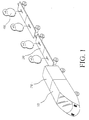
- Fig. 1 is an assembled perspective view of a three-dimensional built-up toy train according to a preferred embodiment of the present invention.
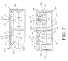
- the entire toy train of the present invention is built up from a plurality of modeled flat parts that are directly stamped on thin plates, as shown in Figs. 2, 3 and 4.
- the modeled flat parts could be assembled into a front locomotive 10, a back locomotive 20, a plurality of two-section passenger cars 30, and a plurality of toy passengers 40.
- Each front locomotive 10 includes two front locomotive walls 10, each of which is a locomotive-shaped flat part having a beveled front edge.
- Each of the two front locomotive walls 10 is provided near front and rear ends of a straight lower edge with two slits 101, at the beveled front edge with a first recess 102, and on a straight upper edge at a predetermined position with a second recess 103.
- a first front locating part 13 is provided on an upper edge near two outer ends with two slits 131 for engaging with the two front slits 101 separately on the lower edges of the two front locomotive walls 10, and on a lower edge with a central slit 131 for engaging with a supporting part 15.
- a second front locating part 14 is symmetrically provided on an upper edge near two outer ends with two pairs of slits 141 for engaging with the two rear slits 101 separately on the lower edges of the two front locomotive walls 10, and provided on a lower edge with a central slit 141 for engaging with the supporting part 15, too.
- the supporting part 15 is provided on an upper edge with two spaced slits 151 for engaging with the central slits 131 and 141, and on a lower edge with a central slit 151 for engaging with a slit 161 at an upper side of a wheel holder 16.
- the wheel holder 16 is provided at a lower side with two sideward projected round heads 162 to rotatably support two round wheels 17.
- Each back locomotive 20 includes two back locomotive walls 20, each of which is a flat part being provided on a lower edge with three spaced slits 201, and on an upper edge with a recess 202. There are also a flat part for a back roof 21 that is provided at two lateral sides with two tabs 212 adapted to engage with the two recesses 102 at the upper edges of the two back locomotive walls 20.
- a first back locating part 22 is symmetrically provided on an upper edge near two outer ends with two pairs of slits 221 for engaging with the most front slits 201 on the lower edges of the two back locomotive walls 20, and provided on a lower edge with a central slit 221 for engaging with a link part 24.
- a second back locating part 23 is provided on an upper edge near two outer ends with two slits 231 for engaging with the middle slits 201 on the lower edges of the two back locomotive walls 20, and on a lower edge with a central slit 231 for engaging with the link part 24.
- a stopper part 25 is engaged at two upward opened slits 251 with the two rear slits 201 of the two back locomotive walls 20.
- the link part 24 is provided on an upper edge near a front portion thereof with two spaced slits 241 for separately engaging with the central slits 221, 231 on the lower edges of the first and the second back locating parts 22, 23; on a lower edge of the front portion with a central slit 241 for engaging with a slit 261 on an upper side of a wheel holder 26; and on the lower edge of a rear portion of the link part 24 with a downward extended round head 242 for engaging with a ring-shaped end of a connector 29 or 34, of which another ring-shaped end is connected to one passenger car 30 as will described in more details later.
- the wheel holder 26 is provided at a lower side with two laterally extended round heads 262 to rotatably support two wheels 27 thereon.
- Two coupling parts 28 are provided on a lower edge with two spaced slits 281 for separately engaging with two upper slits 141, 221 of the second front locating part 14 and the first back locating part 22.
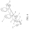
- each two-section passenger car includes two floor parts 30, each of which being provided at two lateral sides with two side slits 301 for engaging with a wheel holder 31 and at a center with an axially extended insertion hole 302 for a toy passenger 40 to insert therein. Since there are two symmetrical sets of flat parts for forming the two-section passenger car 30, only one set of the flat parts is described herein.
- the wheel holder 31 is provided on a lower side with two spaced slits 311 for separately engaging with a slit 331 provided on an upper edge at an end of a long coupling 33, on the lower side at two outer ends thereof with two laterally extended round heads 312 for rotatably supporting two wheel parts 35, on an upper side with a central slit 311 for engaging with a link part 32, and on the upper side at two outer ends thereof with two upward extensions 313 for engaging with the side slits 301 on the floor part 30.
- the link part 32 is provided on a first end portion of a lower edge with a central slit 321 for engaging with the central slits 311 on the upper side of the wheel holder 31, and at an outmost end of a second portion of the lower edge with a downward extended round head 322 for engaging with an ring-shaped end of a connector 34, another ring-shaped end of which is engaged with the downward extended round head 242 of the link part 24.
- Each long coupling 33 engaged at an end with one lower slit 311 of the wheel holder 31 is provided on the upper edge at another end with another slit 331 for engaging with a lower slit 311 of another wheel holder 31 connected to a next passenger car 30, so as to couple two adjacent passenger cars 30.
- Wheels 17 may be rotatably mounted onto the two laterally extended round heads 162 of the wheel holder 16 before the latter is connected to the supporting part 15. Thereafter, the windshield 11 and the front roof 12 are connected to the front locomotive walls 10 by engaging the tabs 111, 121 of the windshield 11 and the front roof 12 with the recesses 102, 103 of the front locomotive walls 10, respectively.
- the stopper part 25 is connected to the walls 20 by engaging the two slits 251 with the two rear slits 201 of the walls 20.
- each section of the two-section passenger car 30 by rotatably mounting the two wheel parts 35 onto the laterally extended round heads 312 of the wheel holder 31, and engage the two upward extensions 313 of the wheel holder 31 with the two side slits 301 of the floor part 30. Then, connect the link part 32 to the wheel holder 31 by engaging the lower slit 321 of the link part 32 with the upper central slit 311 between the two upward extensions 313 of the wheel holder 31. Finally, connect the two coupling parts 33 to the wheel holder 31 by engaging two upper slits 331 at an end of the coupling parts 33 with the two lower slits 311 of the wheel holder 31. At this point, one section of the two-section passenger car 30 is formed.
- the connectors 29 and 34 are used to connect the locomotive of the toy train to the first two-section passenger car 30 and a preceding two-section passenger car 30 to a following two-section passenger car 30 by separately engaging two ring-shaped ends of each connector 29, 34 with the round heads 242, 322 of two adjacent link parts 24, 32 or two round heads 322 of two adjacent link parts 32.
- the toy passengers 40 may be connected to the passenger car 30 by inserting a lower tab 41 of the toy passenger 40 into the central slit 302 of the floor part 30, as shown in Fig. 4.
- a player may employ his or her imagination and thinking ability to assemble the various flat parts in different ways into a toy train. Differently shaped toy passengers may be provided to increase the fun of the toy train. To create more fun, the toy passengers may be differently designed cartoon figures, or figures of famous performers or politicians.
- Fig. 5 shows another set of various flat parts for assembling into a second embodiment of the passenger car.
- the passenger car of this embodiment is a one-section passenger car and is built up from a flat floor part 50 having two side slits 501 and a central slit 502 for a toy passenger 55 to connect thereto; a wheel holder 51 being provided on a lower edge near two outer ends with two slits 511, on the lower edge at two outer ends with two laterally extended round heads 512, on an upper edge at two outer ends with two upward extensions 512 for engaging with the two side slits 501 of the floor part 50, and on the upper edge with a central slit 511; two wheel parts 54 rotatably mounted on the two round heads 512 of the wheel holder 51; a link part'52 being provided on a lower edge with a central slit 521 for engaging with the upper central slit 511 of the wheel holder 51 and on the lower edge at two outer ends with two downward extended round heads 522; and
Landscapes
- Toys (AREA)
Applications Claiming Priority (2)
| Application Number | Priority Date | Filing Date | Title |
|---|---|---|---|
| DE20114592U DE20114592U1 (de) | 2001-09-05 | 2001-09-05 | Dreidimensionaler zusammengesetzter Spielzeugzug |
| DE20114592U | 2001-09-05 |
Publications (2)
| Publication Number | Publication Date |
|---|---|
| EP1291052A2 true EP1291052A2 (fr) | 2003-03-12 |
| EP1291052A3 EP1291052A3 (fr) | 2003-11-05 |
Family
ID=7961300
Family Applications (1)
| Application Number | Title | Priority Date | Filing Date |
|---|---|---|---|
| EP01124403A Withdrawn EP1291052A3 (fr) | 2001-09-05 | 2001-10-11 | Train jouet en trois dimensions constitué d'éléments à assembler |
Country Status (2)
| Country | Link |
|---|---|
| EP (1) | EP1291052A3 (fr) |
| DE (1) | DE20114592U1 (fr) |
Families Citing this family (1)
| Publication number | Priority date | Publication date | Assignee | Title |
|---|---|---|---|---|
| CN115035647B (zh) * | 2022-06-16 | 2024-08-20 | 浙江树人学院 | 一种亲子高铁车厢系统及该系统使用方法 |
Family Cites Families (5)
| Publication number | Priority date | Publication date | Assignee | Title |
|---|---|---|---|---|
| US1547176A (en) * | 1924-01-28 | 1925-07-28 | Samuel L Lazaron | Combined souvenir and advertising toy and box |
| US2823844A (en) * | 1951-04-17 | 1958-02-18 | William P Frankenstein | Simulated wheeled toy carton |
| FR1047344A (fr) * | 1951-04-30 | 1953-12-14 | Caisse de carton combinée avec des éléments amovibles pour pouvoir se transformer en véhicule-jouet | |
| US2712711A (en) * | 1951-12-10 | 1955-07-12 | Theodore J Leyden | Toy vehicle formed from carton |
| JPS5618387Y2 (fr) * | 1975-11-27 | 1981-04-30 |
-
2001
- 2001-09-05 DE DE20114592U patent/DE20114592U1/de not_active Expired - Lifetime
- 2001-10-11 EP EP01124403A patent/EP1291052A3/fr not_active Withdrawn
Also Published As
| Publication number | Publication date |
|---|---|
| EP1291052A3 (fr) | 2003-11-05 |
| DE20114592U1 (de) | 2002-02-21 |
Similar Documents
| Publication | Publication Date | Title |
|---|---|---|
| JPH0428636Y2 (fr) | ||
| US6015150A (en) | Three-dimensional puzzle assembly | |
| US6475060B1 (en) | Three-dimensional built-up toy train | |
| USD974486S1 (en) | Component for launch toy | |
| US6439945B1 (en) | Octopus-shaped built-up toy | |
| US4148152A (en) | Construction toy with reversible track having sound producing means | |
| US20060135032A1 (en) | Three-dimensional coloring product | |
| EP1291052A2 (fr) | Train jouet en trois dimensions constitué d'éléments à assembler | |
| US7140944B2 (en) | Connecting toy | |
| JP3781827B2 (ja) | 玩具車 | |
| US4771943A (en) | Train track and track bed assembly | |
| US3854405A (en) | High performance model vehicle racetrack | |
| JP3182102B2 (ja) | 幼児用遊具としての組立式家屋 | |
| CN215741776U (zh) | 一种变形玩具车及设有其的机器人和玩具火车 | |
| CN101991958A (zh) | 轨道模型车辆的自动连接器 | |
| CN101264390B (zh) | 一种玩具飞车装置 | |
| CN201200809Y (zh) | 一种玩具飞车装置 | |
| US6475053B1 (en) | Crab-shaped built-up toy | |
| KR200299526Y1 (ko) | 다용도 완구 | |
| CN218501248U (zh) | 一种变形机器人 | |
| USD1074859S1 (en) | Toy train track connector | |
| KR200256680Y1 (ko) | 두뇌 계발(頭腦 啓發)에 유리한 입체 기차 조립 장난감 | |
| JP3060834U (ja) | 立体交差式多片組合せ玩具 | |
| KR200250803Y1 (ko) | 완구용 조립식 레일의 구조 | |
| JPH0615664Y2 (ja) | 走行玩具の連結構造 |
Legal Events
| Date | Code | Title | Description |
|---|---|---|---|
| PUAI | Public reference made under article 153(3) epc to a published international application that has entered the european phase |
Free format text: ORIGINAL CODE: 0009012 |
|
| AK | Designated contracting states |
Kind code of ref document: A2 Designated state(s): AT BE CH CY DE DK ES FI FR GB GR IE IT LI LU MC NL PT SE TR Designated state(s): AT BE CH CY DE DK ES FI FR GB GR IE IT LI LU MC NL PT SE TR |
|
| AX | Request for extension of the european patent |
Extension state: AL LT LV MK RO SI |
|
| PUAL | Search report despatched |
Free format text: ORIGINAL CODE: 0009013 |
|
| AK | Designated contracting states |
Kind code of ref document: A3 Designated state(s): AT BE CH CY DE DK ES FI FR GB GR IE IT LI LU MC NL PT SE TR |
|
| AX | Request for extension of the european patent |
Extension state: AL LT LV MK RO SI |
|
| AKX | Designation fees paid | ||
| REG | Reference to a national code |
Ref country code: DE Ref legal event code: 8566 |
|
| STAA | Information on the status of an ep patent application or granted ep patent |
Free format text: STATUS: THE APPLICATION IS DEEMED TO BE WITHDRAWN |
|
| 18D | Application deemed to be withdrawn |
Effective date: 20040501 |