EP1291736A2 - Luftschneide zum Wellen von Papierblättern - Google Patents
Luftschneide zum Wellen von Papierblättern Download PDFInfo
- Publication number
- EP1291736A2 EP1291736A2 EP02255906A EP02255906A EP1291736A2 EP 1291736 A2 EP1291736 A2 EP 1291736A2 EP 02255906 A EP02255906 A EP 02255906A EP 02255906 A EP02255906 A EP 02255906A EP 1291736 A2 EP1291736 A2 EP 1291736A2
- Authority
- EP
- European Patent Office
- Prior art keywords
- air
- sheet
- manifold
- roll
- image
- Prior art date
- Legal status (The legal status is an assumption and is not a legal conclusion. Google has not performed a legal analysis and makes no representation as to the accuracy of the status listed.)
- Withdrawn
Links
- 239000000758 substrate Substances 0.000 claims description 4
- 238000000151 deposition Methods 0.000 claims description 2
- 108091008695 photoreceptors Proteins 0.000 description 13
- 239000000463 material Substances 0.000 description 8
- 239000002245 particle Substances 0.000 description 8
- 239000000843 powder Substances 0.000 description 8
- 238000003384 imaging method Methods 0.000 description 6
- 238000000034 method Methods 0.000 description 5
- 238000000926 separation method Methods 0.000 description 3
- 238000004140 cleaning Methods 0.000 description 2
- 239000002131 composite material Substances 0.000 description 2
- 239000008187 granular material Substances 0.000 description 2
- 230000009191 jumping Effects 0.000 description 2
- 238000003491 array Methods 0.000 description 1
- 230000015556 catabolic process Effects 0.000 description 1
- 238000001816 cooling Methods 0.000 description 1
- 238000006731 degradation reaction Methods 0.000 description 1
- 238000007599 discharging Methods 0.000 description 1
- 150000002500 ions Chemical class 0.000 description 1
- 239000011159 matrix material Substances 0.000 description 1
- 239000007921 spray Substances 0.000 description 1
Images


Classifications
-
- B—PERFORMING OPERATIONS; TRANSPORTING
- B65—CONVEYING; PACKING; STORING; HANDLING THIN OR FILAMENTARY MATERIAL
- B65H—HANDLING THIN OR FILAMENTARY MATERIAL, e.g. SHEETS, WEBS, CABLES
- B65H29/00—Delivering or advancing articles from machines; Advancing articles to or into piles
- B65H29/54—Article strippers, e.g. for stripping from advancing elements
-
- G—PHYSICS
- G03—PHOTOGRAPHY; CINEMATOGRAPHY; ANALOGOUS TECHNIQUES USING WAVES OTHER THAN OPTICAL WAVES; ELECTROGRAPHY; HOLOGRAPHY
- G03G—ELECTROGRAPHY; ELECTROPHOTOGRAPHY; MAGNETOGRAPHY
- G03G15/00—Apparatus for electrographic processes using a charge pattern
- G03G15/20—Apparatus for electrographic processes using a charge pattern for fixing, e.g. by using heat
- G03G15/2003—Apparatus for electrographic processes using a charge pattern for fixing, e.g. by using heat using heat
- G03G15/2014—Apparatus for electrographic processes using a charge pattern for fixing, e.g. by using heat using heat using contact heat
- G03G15/2017—Structural details of the fixing unit in general, e.g. cooling means, heat shielding means
- G03G15/2028—Structural details of the fixing unit in general, e.g. cooling means, heat shielding means with means for handling the copy material in the fixing nip, e.g. introduction guides, stripping means
-
- B—PERFORMING OPERATIONS; TRANSPORTING
- B65—CONVEYING; PACKING; STORING; HANDLING THIN OR FILAMENTARY MATERIAL
- B65H—HANDLING THIN OR FILAMENTARY MATERIAL, e.g. SHEETS, WEBS, CABLES
- B65H2406/00—Means using fluid
- B65H2406/10—Means using fluid made only for exhausting gaseous medium
- B65H2406/12—Means using fluid made only for exhausting gaseous medium producing gas blast
- B65H2406/122—Nozzles
Definitions
- This invention relates generally to an air knife and more particularly, concerns a multi function corrugating air knife to remove a sheet from a fusing member in a full color electrophotographic printing machine.
- a photoconductive member is charged to a substantially uniform potential so as to sensitize the surface thereof.
- the charged portion of the photoconductive member is exposed to a light image of an original document being reproduced. Exposure of the charged photoconductive member selectively dissipates the charges thereon in the irradiated areas.
- the latent image is developed by bringing a developer material into contact therewith.
- the developer material comprises toner particles adhering triboelectrically to carrier granules.
- the toner particles are attracted from the carrier granules to the latent image forming a toner powder image on the photoconductive member.
- the toner powder image is then transferred from the photoconductive member to a copy sheet.
- the toner particles are heated to permanently affix the powder image to the copy sheet.
- the foregoing generally describes a typical black and white electrophotographic printing machine.
- an architecture which comprises a plurality of image forming stations.
- One example of the plural image forming station architecture utilizes an image-on-image (IOI) system in which the photoreceptive member is recharged, re-imaged and developed for each color separation.
- IIOI image-on-image
- This charging, imaging, developing and recharging, re-imaging and developing, all followed by transfer to paper is done in a single revolution of the photoreceptor in so-called single pass machines, while multipass architectures form each color separation with a single charge, image and develop, with separate transfer operations for each color.
- a corrugating air knife comprising a manifold connected to an air supply source, wherein said manifold defines an outlet for providing a directed stream of air from said manifold and a plurality of secondary outlets connected to said manifold which direct a localized stream of air to corrugate a sheet.
- a device for fusing a toner image to a sheet comprising a heated fusing roll, a pressure roll in circumferential contact with said heated fusing roll to form a nip therebetween, a manifold, adjacent said the nip formed by said heated fusing roll and said pressure roll, said manifold connected to an air supply source, wherein said manifold defines an outlet for providing a directed stream of air from said manifold and a plurality of secondary outlets connected to said manifold which direct a localized stream of air to corrugate a sheet.
- an electrophotographic printing machine having a fusing apparatus, comprising a print engine for forming and depositing a toner image on a substrate, a heated fusing roll, a pressure roll in circumferential contact with said heated fusing roll to form a nip therebetween, a manifold, adjacent said the nip formed by said heated fusing roll and said pressure roll, said manifold connected to an air supply source, wherein said manifold defines an outlet for providing a directed stream of air from said manifold and a plurality of secondary outlets connected to said manifold which direct a localized stream of air to corrugate a sheet.
- This invention relates to printing system which is used to produce color output in a single pass of a photoreceptor belt. It will be understood, however, it is intended to cover a multi-pass color process system, a single or multiple pass highlight color system and a black and white printing system.
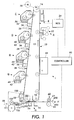
- the electrophotographic printing machine of the present invention uses a charge retentive surface in the form of an Active Matrix (AMAT) photoreceptor belt 10 supported for movement in the direction indicated by arrow 12, for advancing sequentially through the various xerographic process stations.
- the belt is entrained about a drive roller 14 and tension and steering rollers 16 and 18 respectively; roller 14 is operatively connected to a drive motor 20 for effecting movement of the belt through the xerographic stations.
- AMAT Active Matrix
- a portion of belt 10 passes through charging station A where a corona generating device, indicated generally by the reference numeral 22, charges the photoconductive surface of belt 10 to a relative high, substantially uniform, preferably negative potential.
- the charged portion of photoconductive surface is advanced through an imaging station B.
- the uniformly charged belt 10 is exposed to a laser based output scanning device 24 which causes the charge retentive surface to be discharged in accordance with the output from the scanning device.
- the scanning device is a laser Raster Output Scanner (ROS).
- ROS Raster Output Scanner
- the ROS could be replaced by other xerographic exposure devices such as LED arrays.
- the photoreceptor which is initially charged to a voltage V c , undergoes dark decay to a level V ddp equal to about -500 volts. When exposed at the exposure station B it is discharged to V image equal to about -50 volts. Thus after exposure, the photoreceptor contains a monopolar voltage profile of high and low voltages, the former corresponding to charged areas and the latter corresponding to discharged or image areas.
- developer structure indicated generally by the reference numeral 32 utilizing a hybrid jumping development (HJD) system
- the development roll better known as the donor roll
- the first field is the AC jumping field which is used for toner cloud generation.
- the second field is the DC development field which is used to control the amount of developed toner mass on the photoreceptor.
- the toner cloud causes charged toner particles 26 to be attracted to the electrostatic latent image. Appropriate developer biasing is accomplished via a power supply.
- This type of system is a non-contact type in which only toner particles (magenta, for example) are attracted to the latent image and there is no mechanical contact between the photoreceptor and a toner delivery device to disturb a previously developed, but unfixed, image.
- toner particles magenta, for example
- the developed but unfixed image is then transported past a second charging device 36 where the photoreceptor and previously developed toner image areas are recharged to a predetermined level.
- a second exposure/imaging is performed by imaging device 38 which comprises a laser based output structure and is utilized for selectively discharging the photoreceptor on toned areas and/or bare areas, pursuant to the image to be developed with the second color toner.
- the photoreceptor contains toned and untoned areas at relatively high voltage levels and toned and untoned areas at relatively low voltage levels. These low voltage areas represent image areas which are developed using discharged area development (DAD).
- DAD discharged area development
- a negatively charged, developer material 40 comprising color toner is employed.
- the toner which by way of example may be yellow, is contained in a developer housing structure 42 disposed at a second developer station D and is presented to the latent images on the photoreceptor by way of a second HSD developer system.
- a power supply (not shown) serves to electrically bias the developer structure to a level effective to develop the discharged image areas with negatively charged yellow toner particles 40.
- a negative pre-transfer dicorotron member 50 is provided to condition the toner for effective transfer to a substrate using positive corona discharge.
- a sheet of support material 52 is moved into contact with the toner images at transfer station G.
- the sheet of support material is advanced to transfer station G by a sheet feeding apparatus to the pre-transfer device which directs the advancing sheet of support material into contact with photoconductive surface of belt 10 in a timed sequence so that the toner powder image developed thereon contacts the advancing sheet of support material at transfer station G.
- Transfer station G includes a transfer dicorotron 54 which sprays positive ions onto the backside of sheet 52. This attracts the negatively charged toner powder images from the belt 10 to sheet 52.
- a detack dicorotron 56 is provided for facilitating stripping of the sheets from the belt 10.
- Fusing station H includes a fuser assembly, indicated generally by the reference numeral 60, which permanently affixes the transferred powder image to sheet 52.
- fuser assembly 60 comprises a heated fuser roller 62 and a backup or pressure roller 64.
- Sheet 52 passes between fuser roller 62 and backup roller 64 with the toner powder image contacting fuser roller 62. In this manner, the toner powder images are permanently affixed to sheet 52 after it is allowed to cool.
- the sheet is separated from the fuser roll by the corrugating air knife, described in more detail below, to a chute, not shown, which guides the advancing sheets 52 to a catch tray, not shown, for subsequent removal from the printing machine by the operator.
- the residual toner particles carried by the non-image areas on the photoconductive surface are removed therefrom. These particles are removed at cleaning station I using a cleaning brush structure contained in a housing 66.
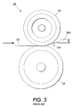
- a sheet 52 passes between the heated roll 62 and the pressure roll 64 causing the toner image thereon to be fused to the sheet.
- an air knife 300 provide a stream of air to assist in separating the fused sheet from the heated fuser roll.
- the air blast from the air knife on a light weight sheet would cause the lead edge of the sheet to fold over while the imaged area "retacked" to the fuser roll 62. This would cause the sheet to wrap around the fuser roll 62 causing a jam as opposed to exiting through the sheet guide.
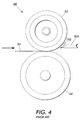
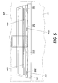
- the corrugating air knife 400 utilizes a manifold 401 which directs stream of air across the width of the sheet but further has extra ribs 402 formed which have a air passage integral to the rib 402 as shown in Fig 5.
- the localized stream of air which flows from the ribs 402 causes a lightweight sheet to corrugate due to the air stream which increases the beam strength of the sheet and prevents the lead edge of the sheet 152 from folding over and wrapping around the fuser.
- the ribs 402 also provide a gap between the sheet 52 and the main portion of the air knife 400 which helps prevent the sheet from being sucked toward the air knife and by the baffle due to Bernoulli effect.
- the localized jets from the ribs 402 also help to break the surface tension between the sheet 52 and the fuser heated roll 62 which allows the wall of air expelled by the air knife 400 to remove the sheet 52 from the roll 62.
- the control for the air stream is modified to enhance the stripping effect of the air knife.
- a short burst of air was used to separate the lead edge of the sheet from the fuser roll and the air was then discontinued.
- this single burst of air did not prevent retack and wrap jams.
- the solution is to provide an initial burst of air utilizing the localized air jets 402 and then to continue the airstream at a lesser pressure to continue to assist in the separation of the sheet from the fuser. This continued air stream has the additional benefit of cooling the lighter weight sheets to help reduce the chance of hot offset or other damage to the image due to the image not being fully cooled.
- Heavier weight sheets do not absorb as much heat nor is the beam strength such that wrap jams are a problem so the air knife can be used less or even not at all depending of the sheet weight.
- the control for the air knife can be predetermined based on the sheet weight requested for a particular job or by sensing the weight of the sheet as it is processed in the machine and automatically adjusting the air knife in response to the sheet weight.
- a corrugating air knife for stripping a sheet from a fusing member.
- the air knife includes a manifold connected to an air supply source and has an outlet which directs a flow of air across a sheet path adjacent the fuser.
- the air knife further includes ribs through which air flows to create localized air flows which when directed at the sheet cause it to corrugate as it separates from the fuser. The corrugation increases the beam strength and prevents wrap jams.
Landscapes
- Engineering & Computer Science (AREA)
- Mechanical Engineering (AREA)
- Physics & Mathematics (AREA)
- General Physics & Mathematics (AREA)
- Color Electrophotography (AREA)
- Electrostatic Charge, Transfer And Separation In Electrography (AREA)
- Paper (AREA)
Applications Claiming Priority (4)
| Application Number | Priority Date | Filing Date | Title |
|---|---|---|---|
| US31523301P | 2001-08-27 | 2001-08-27 | |
| US315233P | 2001-08-27 | ||
| US10/043,188 US20030049042A1 (en) | 2001-08-27 | 2002-01-14 | Corrugating air knife |
| US43188 | 2002-01-14 |
Publications (2)
| Publication Number | Publication Date |
|---|---|
| EP1291736A2 true EP1291736A2 (de) | 2003-03-12 |
| EP1291736A3 EP1291736A3 (de) | 2003-04-23 |
Family
ID=26720125
Family Applications (1)
| Application Number | Title | Priority Date | Filing Date |
|---|---|---|---|
| EP02255906A Withdrawn EP1291736A3 (de) | 2001-08-27 | 2002-08-23 | Luftschneide zum Wellen von Papierblättern |
Country Status (2)
| Country | Link |
|---|---|
| US (1) | US20030049042A1 (de) |
| EP (1) | EP1291736A3 (de) |
Cited By (1)
| Publication number | Priority date | Publication date | Assignee | Title |
|---|---|---|---|---|
| EP2146254A1 (de) | 2008-06-09 | 2010-01-20 | Xerox Corporation | Druckmaschine und Verfahren zum Betreiben einer Druckmaschine |
Families Citing this family (8)
| Publication number | Priority date | Publication date | Assignee | Title |
|---|---|---|---|---|
| US7751767B2 (en) | 2006-09-07 | 2010-07-06 | Xerox Corporation | Rotatable air knife |
| US20090178298A1 (en) * | 2008-01-15 | 2009-07-16 | Anatoli Anatolyevich Abramov | Device for fluid removal after laser scoring |
| US8280297B2 (en) * | 2008-12-19 | 2012-10-02 | Eastman Kodak Company | Electophotographic borderless printing method and apparatus |
| US20100158545A1 (en) * | 2008-12-19 | 2010-06-24 | Eastman Kodak Company | Electophotographic borderless printing method and apparatus |
| US9248989B2 (en) | 2013-09-03 | 2016-02-02 | Eastman Kodak Company | Positive pressure web wrinkle reduction system |
| US9352923B2 (en) | 2014-02-26 | 2016-05-31 | Eastman Kodak Company | Air shoe with roller providing lateral constraint |
| US9120634B1 (en) * | 2014-02-26 | 2015-09-01 | Eastman Kodak Company | Media guiding system using bernoulli force roller |
| US9079736B1 (en) | 2014-02-26 | 2015-07-14 | Eastman Kodak Company | Wrinkle reduction system using Bernoulli force rollers |
Family Cites Families (19)
| Publication number | Priority date | Publication date | Assignee | Title |
|---|---|---|---|---|
| US1595478A (en) * | 1920-05-25 | 1926-08-10 | Minton Ogden | Method of stripping and feeding paper and apparatus |
| US3804401A (en) * | 1972-10-30 | 1974-04-16 | Xerox Corp | Pneumatic stripping apparatus |
| US4168830A (en) * | 1975-04-07 | 1979-09-25 | Savin Corporation | Air jet paper pick-off for liquid developer electrostatic copier |
| US4185399A (en) * | 1978-10-02 | 1980-01-29 | E.B. Eddy Forest Products, Ltd. | Doctor blade, drying or sealing assembly |
| US4338391A (en) * | 1979-03-02 | 1982-07-06 | E. I. Du Pont De Nemours And Company | Magnetic resist printing process, composition and apparatus |
| SE8201904L (sv) * | 1982-03-25 | 1983-09-26 | Svenska Flaektfabriken Ab | Anordning vid cylindertork |
| FI68278C (fi) * | 1983-03-01 | 1985-08-12 | Valmet Oy | Fickventilationsanordning foer en maongcylindertork i en pappersmaskin |
| JPS60247672A (ja) * | 1984-05-24 | 1985-12-07 | Fuji Xerox Co Ltd | 用紙剥離装置 |
| JPS6162087A (ja) * | 1984-09-03 | 1986-03-29 | Fuji Xerox Co Ltd | フユ−ザ−ロ−ルの用紙剥離装置 |
| JPH0381791A (ja) * | 1989-08-25 | 1991-04-08 | Hitachi Koki Co Ltd | 電子写真装置の用紙剥離装置 |
| US5208638A (en) * | 1990-06-29 | 1993-05-04 | Olin Corporation | Intermediate transfer surface and method of color printing |
| US6096427A (en) * | 1998-07-27 | 2000-08-01 | Eastman Kodak Company | Fuser belts with adhesion promoting layer |
| JP2000089603A (ja) * | 1998-09-09 | 2000-03-31 | Fuji Xerox Co Ltd | 剥離装置及びこれを用いた定着装置 |
| US6208827B1 (en) * | 1998-11-20 | 2001-03-27 | Eastman Kodak Company | Dual function air skive assembly for reproduction apparatus fuser rollers |
| US6505832B2 (en) * | 1998-12-23 | 2003-01-14 | Xerox Corporation | Variable acceleration take-away roll (TAR) for high capacity feeder |
| JP2002091223A (ja) * | 2000-09-18 | 2002-03-27 | Fuji Xerox Co Ltd | 画像形成装置および定着装置 |
| US6754457B2 (en) * | 2001-04-06 | 2004-06-22 | Nexpress Solutions Llc | Pre-heater for an electrostatographic reproduction apparatus fusing assembly |
| US6505030B1 (en) * | 2001-08-23 | 2003-01-07 | Xerox Corporation | Pre-fuser transport assembly for handling a variety of sheets, and a reproduction machine having same |
| US20030039491A1 (en) * | 2001-08-27 | 2003-02-27 | Bogoshian Gregory V. | Multi-function air knife |
-
2002
- 2002-01-14 US US10/043,188 patent/US20030049042A1/en not_active Abandoned
- 2002-08-23 EP EP02255906A patent/EP1291736A3/de not_active Withdrawn
Cited By (2)
| Publication number | Priority date | Publication date | Assignee | Title |
|---|---|---|---|---|
| EP2146254A1 (de) | 2008-06-09 | 2010-01-20 | Xerox Corporation | Druckmaschine und Verfahren zum Betreiben einer Druckmaschine |
| US7965969B2 (en) | 2008-06-09 | 2011-06-21 | Xerox Corporation | Active rotation of air knife for increased performance |
Also Published As
| Publication number | Publication date |
|---|---|
| US20030049042A1 (en) | 2003-03-13 |
| EP1291736A3 (de) | 2003-04-23 |
Similar Documents
| Publication | Publication Date | Title |
|---|---|---|
| EP1288736A2 (de) | Multifunktionaler Luftmesser | |
| US5850589A (en) | Sheet moisture replacement system using water jet technology | |
| EP0905574B1 (de) | Feuchtigkeitskontrolle zur Beseitigung von Blattwellungen | |
| US9091970B2 (en) | Transfer device, image forming apparatus, and transfer method | |
| US6055409A (en) | Sheet pre-transfer device | |
| US6606478B2 (en) | Composite transfer assist blade | |
| US5987301A (en) | Paper conditioning system | |
| US7720401B2 (en) | Inter-document zone gloss defect eliminator | |
| EP1291736A2 (de) | Luftschneide zum Wellen von Papierblättern | |
| US6823166B2 (en) | Image bearing apparatus that collects image bearing bodies at a common place | |
| US5895154A (en) | Textured rollers for paper conditioning | |
| US5920751A (en) | Apparatus and method for controlling moisture and cooling rate for paper curl reduction | |
| US20020057931A1 (en) | Image forming apparatus including transfer belt having first and second image transfer surface planes arranged at an angle, and plural image bearing members facing same | |
| US7751767B2 (en) | Rotatable air knife | |
| JP3346063B2 (ja) | 画像転写装置 | |
| US5930578A (en) | Moisturizing rolls with end grooves for eliminating water spill from their ends | |
| JP4350240B2 (ja) | 電子写真プリントマシン | |
| US6249667B1 (en) | Conditioner rolls end seals | |
| US5832359A (en) | Apparatus and method for sensing water film thickness on conditioner rolls | |
| US5012290A (en) | Increased transference of a toner image on to a copy sheet by using a zero tension loop applied after corotron transfer | |
| US6292645B1 (en) | Apparatus and method for minimizing the halo effect in an electrostatographic printing system | |
| US8422933B2 (en) | Curved pre-fuser transport to enable larger sheets through a xerographic print engine | |
| JPH06301296A (ja) | 低応力での感光体ベルトからの用紙の剥離 | |
| US6574450B2 (en) | Sheet pre-transfer device | |
| JP2001194972A (ja) | 再調整式光源を備えた印刷機械 |
Legal Events
| Date | Code | Title | Description |
|---|---|---|---|
| PUAI | Public reference made under article 153(3) epc to a published international application that has entered the european phase |
Free format text: ORIGINAL CODE: 0009012 |
|
| PUAL | Search report despatched |
Free format text: ORIGINAL CODE: 0009013 |
|
| AK | Designated contracting states |
Kind code of ref document: A2 Designated state(s): AT BE BG CH CY CZ DE DK EE ES FI FR GB GR IE IT LI LU MC NL PT SE SK TR Designated state(s): AT BE BG CH CY CZ DE DK EE ES FI FR GB GR IE IT LI LU MC NL PT SE SK TR |
|
| AX | Request for extension of the european patent |
Extension state: AL LT LV MK RO SI |
|
| AK | Designated contracting states |
Designated state(s): AT BE BG CH CY CZ DE DK EE ES FI FR GB GR IE IT LI LU MC NL PT SE SK TR |
|
| AX | Request for extension of the european patent |
Extension state: AL LT LV MK RO SI |
|
| 17P | Request for examination filed |
Effective date: 20031023 |
|
| AKX | Designation fees paid |
Designated state(s): DE FR GB |
|
| 17Q | First examination report despatched |
Effective date: 20041008 |
|
| STAA | Information on the status of an ep patent application or granted ep patent |
Free format text: STATUS: THE APPLICATION IS DEEMED TO BE WITHDRAWN |
|
| 18D | Application deemed to be withdrawn |
Effective date: 20050221 |