EP1291808A2 - Stoppmarkierungsserkennungsgerät für Fahrunterstützungssysteme für Fahrzeuge - Google Patents
Stoppmarkierungsserkennungsgerät für Fahrunterstützungssysteme für Fahrzeuge Download PDFInfo
- Publication number
- EP1291808A2 EP1291808A2 EP02020066A EP02020066A EP1291808A2 EP 1291808 A2 EP1291808 A2 EP 1291808A2 EP 02020066 A EP02020066 A EP 02020066A EP 02020066 A EP02020066 A EP 02020066A EP 1291808 A2 EP1291808 A2 EP 1291808A2
- Authority
- EP
- European Patent Office
- Prior art keywords
- stop marker
- vehicle
- area
- stop
- brightness
- Prior art date
- Legal status (The legal status is an assumption and is not a legal conclusion. Google has not performed a legal analysis and makes no representation as to the accuracy of the status listed.)
- Granted
Links
- 239000003550 marker Substances 0.000 title claims abstract description 109
- 239000007787 solid Substances 0.000 claims abstract description 31
- 238000005516 engineering process Methods 0.000 description 6
- 230000003287 optical effect Effects 0.000 description 5
- 238000011156 evaluation Methods 0.000 description 2
- 238000000034 method Methods 0.000 description 1
- 238000012986 modification Methods 0.000 description 1
- 230000004048 modification Effects 0.000 description 1
Images


Classifications
-
- B—PERFORMING OPERATIONS; TRANSPORTING
- B60—VEHICLES IN GENERAL
- B60W—CONJOINT CONTROL OF VEHICLE SUB-UNITS OF DIFFERENT TYPE OR DIFFERENT FUNCTION; CONTROL SYSTEMS SPECIALLY ADAPTED FOR HYBRID VEHICLES; ROAD VEHICLE DRIVE CONTROL SYSTEMS FOR PURPOSES NOT RELATED TO THE CONTROL OF A PARTICULAR SUB-UNIT
- B60W50/00—Details of control systems for road vehicle drive control not related to the control of a particular sub-unit, e.g. process diagnostic or vehicle driver interfaces
- B60W50/08—Interaction between the driver and the control system
- B60W50/12—Limiting control by the driver depending on vehicle state, e.g. interlocking means for the control input for preventing unsafe operation
-
- B—PERFORMING OPERATIONS; TRANSPORTING
- B60—VEHICLES IN GENERAL
- B60W—CONJOINT CONTROL OF VEHICLE SUB-UNITS OF DIFFERENT TYPE OR DIFFERENT FUNCTION; CONTROL SYSTEMS SPECIALLY ADAPTED FOR HYBRID VEHICLES; ROAD VEHICLE DRIVE CONTROL SYSTEMS FOR PURPOSES NOT RELATED TO THE CONTROL OF A PARTICULAR SUB-UNIT
- B60W50/00—Details of control systems for road vehicle drive control not related to the control of a particular sub-unit, e.g. process diagnostic or vehicle driver interfaces
- B60W50/08—Interaction between the driver and the control system
- B60W50/14—Means for informing the driver, warning the driver or prompting a driver intervention
- B60W2050/143—Alarm means
-
- B—PERFORMING OPERATIONS; TRANSPORTING
- B60—VEHICLES IN GENERAL
- B60W—CONJOINT CONTROL OF VEHICLE SUB-UNITS OF DIFFERENT TYPE OR DIFFERENT FUNCTION; CONTROL SYSTEMS SPECIALLY ADAPTED FOR HYBRID VEHICLES; ROAD VEHICLE DRIVE CONTROL SYSTEMS FOR PURPOSES NOT RELATED TO THE CONTROL OF A PARTICULAR SUB-UNIT
- B60W2420/00—Indexing codes relating to the type of sensors based on the principle of their operation
- B60W2420/40—Photo, light or radio wave sensitive means, e.g. infrared sensors
- B60W2420/403—Image sensing, e.g. optical camera
-
- B—PERFORMING OPERATIONS; TRANSPORTING
- B60—VEHICLES IN GENERAL
- B60W—CONJOINT CONTROL OF VEHICLE SUB-UNITS OF DIFFERENT TYPE OR DIFFERENT FUNCTION; CONTROL SYSTEMS SPECIALLY ADAPTED FOR HYBRID VEHICLES; ROAD VEHICLE DRIVE CONTROL SYSTEMS FOR PURPOSES NOT RELATED TO THE CONTROL OF A PARTICULAR SUB-UNIT
- B60W30/00—Purposes of road vehicle drive control systems not related to the control of a particular sub-unit, e.g. of systems using conjoint control of vehicle sub-units
- B60W30/08—Active safety systems predicting or avoiding probable or impending collision or attempting to minimise its consequences
- B60W30/09—Taking automatic action to avoid collision, e.g. braking and steering
-
- G—PHYSICS
- G01—MEASURING; TESTING
- G01S—RADIO DIRECTION-FINDING; RADIO NAVIGATION; DETERMINING DISTANCE OR VELOCITY BY USE OF RADIO WAVES; LOCATING OR PRESENCE-DETECTING BY USE OF THE REFLECTION OR RERADIATION OF RADIO WAVES; ANALOGOUS ARRANGEMENTS USING OTHER WAVES
- G01S11/00—Systems for determining distance or velocity not using reflection or reradiation
- G01S11/12—Systems for determining distance or velocity not using reflection or reradiation using electromagnetic waves other than radio waves
Definitions
- the present invention relates to a stop marker recognition apparatus of a vehicle drive assist system for recognizing a stop marker ahead of a vehicle.
- ITS Intelligent Transport System
- Japanese Patent Application Laid-open No. Toku-Kai 2000-118261 discloses a technology in which an own vehicle automatically follows up a preceding vehicle in a traffic jam, particularly in a stop-and-go traffic condition by electronically controlling a throttle valve and a brake system according to signals of an inter-vehicle distance detecting sensor.
- a particular area extending in a widthwise direction of a vehicle is established in a lower part of an image picture taken by CCD cameras and the area is divided into six small areas. It is judged that a stop marker exists when an average brightness of respective three successive small areas of the six small areas rises from a low level to a high level and then descends from the high level.
- a drive assist system gives a warning to a vehicle operator or a congestion follow-up mode is turned off. Further, in case where a stop marker exists and there is a solid object immediately ahead of the stop marker, while the vehicle is in a standstill, the drive assist system prohibits the vehicle operator from starting the vehicle.
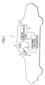
- reference numeral 1 denotes a vehicle (own vehicle) and reference numeral 2 denotes a vehicle drive assist system mounted on the vehicle 1.
- the vehicle drive assist system 2 is constituted by a stereoscopic optical system 3, an image picture processing unit 4 and a warning control apparatus 5.
- the stereoscopic optical system 3 comprises a pair of left and right CCD cameras for taking image pictures of surrounding sceneries of the vehicle and is connected with an image processing unit 4 in which the configuration of roads and solid objects in front of the vehicle and the position thereof are calculated based on image information obtained from the stereoscopic optical system 3.
- the three-dimensional distance distribution is calculated over the entire image picture by processing a pair of left and right stereoscopic images taken by the CCD cameras of the stereoscopic optical system 3 and the configuration of a road or the three-dimensional position of solid objects are detected based on the distance distribution information at high speeds.
- first only white markers on an actual road are extracted from the distance image using the positional information of three-dimension and the configuration of the road is recognized by correcting or modifying parameters of built-in road models so as to agree with the configuration of the actual road based on the extracted white markers.
- the data of a solid object is extracted from the distance image by selecting the data existing above the road surface from the distance image and by deleting noises contained in the distance image. Further, the distance image is divided into a plurality of latticed blocks at a specified interval and one histogram is established for each block. The distance to the solid object is calculated from the histogram. An outline of the object is extracted based on the distance data of the object in respective blocks and the kind of the object is identified based on the configuration, size and position of the object.
- the image processing unit 4 has a function of an solid object recognition means for recognizing a solid object. Further, the image processing unit 4 also has a function of a stop marker recognition apparatus for recognizing a stop marker on a road according to a stop marker judging routine which will be described hereinafter.
- the image processing unit 4 comprises an area brightness detecting means for establishing a particular area in which a stop marker is searched on an original image picture and for detecting a brightness of the area, a brightness change comparisonmeans for comparing the change of time-versus brightness and a stop marker judging means for recognizing a stop marker based on this brightness change.
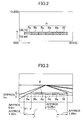
- the original image inputted from the CCD cameras is composed of 512 pixels horizontally and 200 pixels vertically as shown in Fig. 2.
- An area R is established on the rather lower side of the image picture in a widthwise direction of the vehicle, comprising 6 small areas Ra, Rb, Rc, Rd, Re and Rf successively connected in a widthwise direction of the own vehicle, each of which is composed of 65 pixels horizontally and 9 pixels vertically.
- the area R lies 10.35 meters ahead of the own vehicle 1, extending from the own vehicle 1 by approximate 1.5 meters to the right and extending from the own vehicle by approximate 1.3 meters to the left.
- the horizontal length of the small areas Ra, Rb, Rc, Rd, Re and Rf is equivalent to approximate 0.8 meters and the vertical length thereof is equivalent to approximate 1.0 meter.
- An average brightness of three adjacent small areas, Ra, Rb, Rc and Rb, Rc, Rd and Rc, Rd, Re and Rd, Re, Rf is calculated respectively. If the average brightness of a group of the small areas is larger than a threshold value and the average brightness of adjacent groups is smaller than the threshold value, it judged that there is a stop marker in the area R . In this case, such a condition that when all of six small areas concurrently have brightness changes there is a stop marker, is insufficient. This is because there is a possibility that only a long stop marker can be detected and a short stop marker can not be found. Also, there is a possibility that if the own vehicle 1 enters the stop marker diagonally, either of both ends of the small areas comes out of the stop marker.
- the above threshold value is designed to be variable according to the traveling environment. For example, the threshold value is established to a comparatively large value in the sunshine and the threshold value is established to a small value in the shade. Further, the threshold value is established to a large value in the knighting driving.
- the warning control apparatus 5 inputs information about the road configuration, solid objects and the recognized stop marker and when an solid object such as a preceding vehicle is recognized just in front of the stop marker raises an alarm through a warning lamp 8 or a warning buzzer 9 built in a combination meter 7.
- the warning control apparatus 5 acts as a warning control means of the vehicle drive assist system 2.
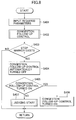
- a stop marker judging routine executed in the image processing unit 4 will be described by reference to a flowchart of Fig. 4.
- This routine is executed every a specified time (for example 20 milliseconds).
- S a step
- required parameters such as brightness information of the area R and the like are inputted.
- the program goes to S102 where an average brightness of the whole area R is calculated and at a next step S103 an average brightness of respective six small areas Ra, Rb, Rc, Rd, Re and Rf is calculated.
- the program goes to S104 where threshold values for the brightness difference judgment are established based on the running circumstance.
- the threshold value is established to a relatively large value.
- the threshold value is established to a small value.
- the threshold value is established to a large value.
- a stop marker warning control executed in the warning control apparatus 5 will be described by reference to a flowchart of Fig. 5.
- the program shown in Fig. 5 is executed every a specified time for example 20 milliseconds.
- required parameters such as information of frontal road configurations, solid objects and stop markers are inputted from the image processing unit 4 to the warning control apparatus 5.
- the program goes to S202 where it is judged whether or not s stop marker exists. If no stop marker exists, the program goes to S203 where it is judged that no alarm is raised and leaves the routine. On the other hand, if a stop marker exists, the program goes to S204 where it is judged whether or not a solid object (preceding vehicle and the like) exists immediately in front of the stop marker.
- the image processing unit 4 surely recognizes a stop marker drawn in the transverse direction of a vehicle on a traveling road. Further, based on the result of recognition of a stop marker, the warning control apparatus 5 gives a vehicle operator a warning so as to stop before the stop marker in case where a preceding vehicle or other solid objects exist when the vehicle enters an intersection. In many cases, roads have a pedestrian crossing in front of a stop marker. This apparatus effectively prevents a vehicle from entering a pedestrian crossing.
- reference numeral 10 denotes a vehicle (own vehicle) and reference numeral 11 denotes a vehicle drive assist system primarily composed of a stereoscopic optical system 3, an image processing unit 4 and a traveling control apparatus 12.
- the traveling control apparatus 12 enters into a known congestion follow-up mode by turning a manual switch 13 on. Describing the function of the congestion follow-up mode specifically, in a traffic jam, when an intervehicle distance between the own vehicle 10 and a preceding vehicle exceeds a predetermined value (for example 6 to 8 meters), the own vehicle 10 catches up with the preceding vehicle by actuating a throttle actuator 14 of the own vehicle 10, automatically opening a throttle valve 15, and controlling the vehicle speed below 30 to 40 kilometers/hour while the brake is exerted. As a result, the intervehicle distance between the own vehicle and the preceding vehicle is kept constant. When the preceding vehicle stops, the own vehicle 10 also stops with a safe intervehicle distance secured. When the own vehicle 10 is in a congestion follow-up mode, the warning lamp 8 in the combination meter 7 is lighted.
- a predetermined value for example 6 to 8 meters
- the traveling control apparatus 12 When a signal indicating that a stop marker exists ahead is inputted from the image processing unit 4 to the traveling control apparatus 12, the congestion follow-up mode described above is automatically turned off so that the own vehicle is prevented from following up a preceding vehicle deeply into pedestrian crossings or intersections.
- the traveling control apparatus 12 has a function as a follow-up running means in the vehicle drive assist system 11.
- Fig. 7 is a flowchart of a congestion follow-up control and this routine is executed every specified time, for example 50 milliseconds.
- required parameters such as road configurations, information of the preceding vehicle or miscellaneous objects, information of stop markers and the like, are inputted from the image processing unit 4.
- the program goes to S302 where the congestion follow-up control is executed.
- the distance to the preceding vehicle is kept constant.
- the program goes to S303 where it is judged whether or not a stop marker exists. In case where a stop marker does not exist, the program returns to START and the congestion follow-up control is performed. In case where a stop marker exists, the program goes to S304 where the congestion follow-up mode is automatically turned off and leaves the routine.
- the congestion follow-up mode is automatically turned off and the own vehicle is effectively prevented from following up the preceding vehicle over the stop marker, for example, into the pedestrian crossing or into the intersection.
- Fig. 8 is a flowchart of a congestion follow-up control according to the third embodiment
- Fig. 9 is a flowchart of a start judging routine according to the third embodiment.
- the feature of the third embodiment is that the congestion follow-up control of the second embodiment is modified depending on the judgment whether a solid object exists or not ahead of the stop marker.
- the program shown in Fig. 8 is executed every a specified time (for example 50 milliseconds).
- required parameters such as frontal road configurations, information of a preceding vehicle, information of other solid objects, are inputted from the image processing unit 4.
- the program goes to S403 where it is judged whether or not a stop marker exists in front of the own vehicle. If there is no stop marker, the program leaves the routine and the congestion follow-up control is performed. If there is a stop marker, the program goes to S404 where the congestion follow-up mode is automatically turned off.
- the program goes to S405 where it is judged whether or not the congestion follow-up mode is manually turned on again. If the switching-on operation of the congestion follow-up mode is manually done, the program goes to S406 where the congestion follow-up mode is turned on and leaves the routine. In case where the switching-on operation of the congestion follow-up mode is not manually done, the program goes to S407 where a start judgment is made in accordance with a start judgment routine which will be described hereinafter and leaves the routine.
- the program goes to S503 where it is judged whether or not the congestion follow-up mode is manually turned on again.
- the program goes to S502 where the normal traveling is performed while the congestion follow-up mode is turned off and leaves the routine.
- the program goes to S504 where it is judged whether or not a solid object exists immediately ahead of the stop marker. In case where no stop marker exists immediately ahead of the stop marker, the program goes to S505 where the congestion follow-up mode is turned on and leaves the routine.
- the vehicle can be effectively prevented from entering intersections or pedestrian crossings by prohibiting the start of the vehicle.
- the stop marker is recognized by obtaining an average brightness of small areas of the area R , however other methods may be allowed to be adopted.
- a plurality of spot sensors 21 may be provided for respective small areas and the stop marker may be judged based on the brightness change detected by these respective spot sensors 21.
Landscapes
- Engineering & Computer Science (AREA)
- Automation & Control Theory (AREA)
- Human Computer Interaction (AREA)
- Transportation (AREA)
- Mechanical Engineering (AREA)
- Traffic Control Systems (AREA)
- Image Processing (AREA)
- Image Analysis (AREA)
- Control Of Driving Devices And Active Controlling Of Vehicle (AREA)
Priority Applications (1)
| Application Number | Priority Date | Filing Date | Title |
|---|---|---|---|
| EP09150229A EP2040199B1 (de) | 2001-09-06 | 2002-09-06 | Stoppmarkierung-Erkennungsvorrichtung für eine Fahrzeugantriebs-Hilfssystem |
Applications Claiming Priority (2)
| Application Number | Priority Date | Filing Date | Title |
|---|---|---|---|
| JP2001270802 | 2001-09-06 | ||
| JP2001270802A JP4541609B2 (ja) | 2001-09-06 | 2001-09-06 | 停止線認識装置、及び、その停止線認識装置を用いた車両用運転支援装置 |
Related Child Applications (1)
| Application Number | Title | Priority Date | Filing Date |
|---|---|---|---|
| EP09150229A Division EP2040199B1 (de) | 2001-09-06 | 2002-09-06 | Stoppmarkierung-Erkennungsvorrichtung für eine Fahrzeugantriebs-Hilfssystem |
Publications (3)
| Publication Number | Publication Date |
|---|---|
| EP1291808A2 true EP1291808A2 (de) | 2003-03-12 |
| EP1291808A3 EP1291808A3 (de) | 2005-11-02 |
| EP1291808B1 EP1291808B1 (de) | 2009-05-20 |
Family
ID=19096410
Family Applications (2)
| Application Number | Title | Priority Date | Filing Date |
|---|---|---|---|
| EP02020066A Expired - Lifetime EP1291808B1 (de) | 2001-09-06 | 2002-09-06 | Fahrunterstützungssystem für Fahrzeuge |
| EP09150229A Expired - Lifetime EP2040199B1 (de) | 2001-09-06 | 2002-09-06 | Stoppmarkierung-Erkennungsvorrichtung für eine Fahrzeugantriebs-Hilfssystem |
Family Applications After (1)
| Application Number | Title | Priority Date | Filing Date |
|---|---|---|---|
| EP09150229A Expired - Lifetime EP2040199B1 (de) | 2001-09-06 | 2002-09-06 | Stoppmarkierung-Erkennungsvorrichtung für eine Fahrzeugantriebs-Hilfssystem |
Country Status (4)
| Country | Link |
|---|---|
| US (1) | US7068154B2 (de) |
| EP (2) | EP1291808B1 (de) |
| JP (1) | JP4541609B2 (de) |
| DE (2) | DE60232393D1 (de) |
Cited By (1)
| Publication number | Priority date | Publication date | Assignee | Title |
|---|---|---|---|---|
| CN105150937A (zh) * | 2015-09-25 | 2015-12-16 | 武汉华安科技股份有限公司 | 一种智能泊车辅助系统及其辅助方法 |
Families Citing this family (19)
| Publication number | Priority date | Publication date | Assignee | Title |
|---|---|---|---|---|
| JP4134894B2 (ja) * | 2003-12-09 | 2008-08-20 | 株式会社デンソー | 車両運転支援装置 |
| JP4296100B2 (ja) * | 2004-02-03 | 2009-07-15 | 株式会社東芝 | 撮像装置 |
| JP4557288B2 (ja) | 2005-01-28 | 2010-10-06 | アイシン・エィ・ダブリュ株式会社 | 画像認識装置及び画像認識方法、並びにそれを用いた位置特定装置、車両制御装置及びナビゲーション装置 |
| JP5151814B2 (ja) * | 2008-08-28 | 2013-02-27 | 株式会社デンソー | 走行区分帯検出装置及び走行区分帯検出装置用プログラム |
| JP5382122B2 (ja) * | 2009-07-31 | 2014-01-08 | 富士通株式会社 | 移動体位置検出装置および移動体位置検出方法 |
| JP2011103080A (ja) * | 2009-11-11 | 2011-05-26 | Fuji Heavy Ind Ltd | 車両情報提示装置 |
| JP5462609B2 (ja) * | 2009-12-09 | 2014-04-02 | 富士重工業株式会社 | 停止線認識装置 |
| DE102010023198A1 (de) * | 2010-06-09 | 2011-12-15 | Gm Global Technology Operations Llc (N.D.Ges.D. Staates Delaware) | Vorrichtung und Verfahren zum Steuern des Fahrverhaltens eines Fahrzeugs bei Annäherung an einen Haltepunkt |
| JP5433525B2 (ja) | 2010-08-06 | 2014-03-05 | 株式会社日立製作所 | 車両走行支援装置及び道路標示の作成方法 |
| JP5720517B2 (ja) * | 2011-09-28 | 2015-05-20 | アイシン・エィ・ダブリュ株式会社 | 停止線検出システム、停止線検出装置、停止線検出方法及びコンピュータプログラム |
| JP5921983B2 (ja) * | 2012-08-03 | 2016-05-24 | クラリオン株式会社 | 車載撮像装置 |
| US9507345B2 (en) | 2014-04-10 | 2016-11-29 | Nissan North America, Inc. | Vehicle control system and method |
| DE102014225383A1 (de) * | 2014-12-10 | 2016-06-16 | Robert Bosch Gmbh | Verfahren zum Betreiben eines Kraftfahrzeugs, Kraftfahrzeug |
| CN105128746A (zh) * | 2015-09-25 | 2015-12-09 | 武汉华安科技股份有限公司 | 一种车辆泊车方法及其泊车系统 |
| JP7151185B2 (ja) * | 2018-06-06 | 2022-10-12 | 株式会社デンソー | 車両制御装置 |
| GB2622490B (en) * | 2019-02-14 | 2024-06-19 | Mobileye Vision Technologies Ltd | Systems and methods for vehicle navigation |
| JP7327083B2 (ja) | 2019-10-30 | 2023-08-16 | 富士通株式会社 | 領域切り出し方法および領域切り出しプログラム |
| US11749000B2 (en) | 2020-12-22 | 2023-09-05 | Waymo Llc | Stop location change detection |
| CN114419930B (zh) * | 2022-03-30 | 2022-07-05 | 智能网联汽车(山东)协同创新研究院有限公司 | 汽车物联网智能信息处理系统 |
Citations (4)
| Publication number | Priority date | Publication date | Assignee | Title |
|---|---|---|---|---|
| JPH05289743A (ja) | 1991-03-28 | 1993-11-05 | Toyota Motor Corp | ライン検出装置 |
| JPH09190537A (ja) | 1996-01-11 | 1997-07-22 | Nippon Soken Inc | 白線検出装置 |
| JP2000118261A (ja) | 1998-10-16 | 2000-04-25 | Toyota Motor Corp | 渋滞追従装置および車両制御装置 |
| EP1096457A2 (de) | 1999-10-29 | 2001-05-02 | Volkswagen Aktiengesellschaft | Verfahren und Einrichtung zur elektronischen Erkennung von Verkehrszeichen |
Family Cites Families (9)
| Publication number | Priority date | Publication date | Assignee | Title |
|---|---|---|---|---|
| US5412487A (en) * | 1991-11-27 | 1995-05-02 | Hitachi, Ltd. | Video camera and apparatus for extracting an object |
| JP3209828B2 (ja) * | 1993-05-25 | 2001-09-17 | 松下電器産業株式会社 | 車間距離計測装置とステレオ画像取り込み装置 |
| JP3153845B2 (ja) * | 1995-05-12 | 2001-04-09 | 三菱電機株式会社 | 路面監視装置及び路面監視方法 |
| US6335689B1 (en) * | 1998-10-16 | 2002-01-01 | Fuji Jukogyo Kabushiki Kaisha | Driver's arousal level estimating apparatus for vehicle and method of estimating arousal level |
| US6226592B1 (en) * | 1999-03-22 | 2001-05-01 | Veridian Erim International, Inc. | Method and apparatus for prompting a motor vehicle operator to remain within a lane |
| JP3174833B2 (ja) * | 1999-10-27 | 2001-06-11 | 建設省土木研究所長 | 右折衝突防止システム |
| JP4414054B2 (ja) * | 2000-03-27 | 2010-02-10 | 本田技研工業株式会社 | 物体認識装置 |
| JP2001289654A (ja) * | 2000-04-11 | 2001-10-19 | Equos Research Co Ltd | ナビゲーション装置、ナビゲーション装置の制御方法、及びそのプログラムを記録した記録媒体 |
| JP4626054B2 (ja) * | 2000-12-21 | 2011-02-02 | 日産自動車株式会社 | 車両用走行制御装置 |
-
2001
- 2001-09-06 JP JP2001270802A patent/JP4541609B2/ja not_active Expired - Fee Related
-
2002
- 2002-09-05 US US10/236,698 patent/US7068154B2/en not_active Expired - Lifetime
- 2002-09-06 DE DE60232393T patent/DE60232393D1/de not_active Expired - Lifetime
- 2002-09-06 DE DE60238880T patent/DE60238880D1/de not_active Expired - Lifetime
- 2002-09-06 EP EP02020066A patent/EP1291808B1/de not_active Expired - Lifetime
- 2002-09-06 EP EP09150229A patent/EP2040199B1/de not_active Expired - Lifetime
Patent Citations (4)
| Publication number | Priority date | Publication date | Assignee | Title |
|---|---|---|---|---|
| JPH05289743A (ja) | 1991-03-28 | 1993-11-05 | Toyota Motor Corp | ライン検出装置 |
| JPH09190537A (ja) | 1996-01-11 | 1997-07-22 | Nippon Soken Inc | 白線検出装置 |
| JP2000118261A (ja) | 1998-10-16 | 2000-04-25 | Toyota Motor Corp | 渋滞追従装置および車両制御装置 |
| EP1096457A2 (de) | 1999-10-29 | 2001-05-02 | Volkswagen Aktiengesellschaft | Verfahren und Einrichtung zur elektronischen Erkennung von Verkehrszeichen |
Cited By (2)
| Publication number | Priority date | Publication date | Assignee | Title |
|---|---|---|---|---|
| CN105150937A (zh) * | 2015-09-25 | 2015-12-16 | 武汉华安科技股份有限公司 | 一种智能泊车辅助系统及其辅助方法 |
| CN105150937B (zh) * | 2015-09-25 | 2017-07-14 | 武汉华安科技股份有限公司 | 一种智能泊车辅助系统及其辅助方法 |
Also Published As
| Publication number | Publication date |
|---|---|
| US20030043030A1 (en) | 2003-03-06 |
| DE60238880D1 (de) | 2011-02-17 |
| JP2003085562A (ja) | 2003-03-20 |
| EP2040199A1 (de) | 2009-03-25 |
| EP2040199B1 (de) | 2011-01-05 |
| JP4541609B2 (ja) | 2010-09-08 |
| EP1291808A3 (de) | 2005-11-02 |
| US7068154B2 (en) | 2006-06-27 |
| DE60232393D1 (de) | 2009-07-02 |
| EP1291808B1 (de) | 2009-05-20 |
Similar Documents
| Publication | Publication Date | Title |
|---|---|---|
| US7068154B2 (en) | Stop marker recognition apparatus of vehicle drive assist system | |
| CN102145693B (zh) | 停车线识别装置 | |
| JP3860061B2 (ja) | 車外監視装置、及び、この車外監視装置を備えた走行制御装置 | |
| JP5679461B2 (ja) | 有効車線区分線を確定する方法及び装置 | |
| EP0896918B1 (de) | Fahrassistenzsystem für Kraftfahrzeuge | |
| US6360170B1 (en) | Rear monitoring system | |
| EP1396732A1 (de) | Fahrzeugkontrollsystem mit einem Apparat zur Fahrzeugumgebungsbeobachtung | |
| US7302325B2 (en) | Vehicle drive assist system | |
| US12606166B2 (en) | Vehicular vision system with determination of right-of-way at intersection | |
| CN114973644B (zh) | 道路信息生成装置 | |
| JP2003063273A (ja) | 車両走行制御装置 | |
| US8160301B2 (en) | Vehicle surroundings monitoring apparatus | |
| KR20140027479A (ko) | 차선 인식 장치 | |
| CN114194186B (zh) | 车辆行驶控制装置 | |
| CN116118741B (zh) | 车辆控制装置 | |
| CN112740220B (zh) | 用于交通灯识别的系统和方法 | |
| JP5355209B2 (ja) | ナビゲーション装置、自車の走行車線の判定方法および判定プログラム | |
| KR102158169B1 (ko) | 차선 인식장치 | |
| JP2005283219A (ja) | 車両走行道路判定方法、車両走行道路判定装置およびナビゲーションシステム | |
| JP2940296B2 (ja) | 駐車車両検出方法 | |
| KR100282903B1 (ko) | 주행도로 차선 이탈 방지장치 | |
| CN118116186A (zh) | 车道推定装置和地图生成装置 | |
| CN116740957B (zh) | 道路识别装置 | |
| KR101816419B1 (ko) | 신호등 영상분석을 이용한 자동 개폐 차단기 | |
| US20240383454A1 (en) | Vehicle and Method of Controlling the Same |
Legal Events
| Date | Code | Title | Description |
|---|---|---|---|
| PUAI | Public reference made under article 153(3) epc to a published international application that has entered the european phase |
Free format text: ORIGINAL CODE: 0009012 |
|
| AK | Designated contracting states |
Kind code of ref document: A2 Designated state(s): AT BE BG CH CY CZ DE DK EE ES FI FR GB GR IE IT LI LU MC NL PT SE SK TR |
|
| AX | Request for extension of the european patent |
Extension state: AL LT LV MK RO SI |
|
| PUAL | Search report despatched |
Free format text: ORIGINAL CODE: 0009013 |
|
| AK | Designated contracting states |
Kind code of ref document: A3 Designated state(s): AT BE BG CH CY CZ DE DK EE ES FI FR GB GR IE IT LI LU MC NL PT SE SK TR |
|
| AX | Request for extension of the european patent |
Extension state: AL LT LV MK RO SI |
|
| 17P | Request for examination filed |
Effective date: 20060502 |
|
| AKX | Designation fees paid |
Designated state(s): DE |
|
| 17Q | First examination report despatched |
Effective date: 20060725 |
|
| 17Q | First examination report despatched |
Effective date: 20060725 |
|
| GRAP | Despatch of communication of intention to grant a patent |
Free format text: ORIGINAL CODE: EPIDOSNIGR1 |
|
| GRAS | Grant fee paid |
Free format text: ORIGINAL CODE: EPIDOSNIGR3 |
|
| RTI1 | Title (correction) |
Free format text: DRIVE ASSIST SYSTEM OF A VEHICLE |
|
| GRAA | (expected) grant |
Free format text: ORIGINAL CODE: 0009210 |
|
| AK | Designated contracting states |
Kind code of ref document: B1 Designated state(s): DE |
|
| REF | Corresponds to: |
Ref document number: 60232393 Country of ref document: DE Date of ref document: 20090702 Kind code of ref document: P |
|
| RIN2 | Information on inventor provided after grant (corrected) |
Inventor name: KUDO, SHINYA |
|
| PLBE | No opposition filed within time limit |
Free format text: ORIGINAL CODE: 0009261 |
|
| STAA | Information on the status of an ep patent application or granted ep patent |
Free format text: STATUS: NO OPPOSITION FILED WITHIN TIME LIMIT |
|
| 26N | No opposition filed |
Effective date: 20100223 |
|
| REG | Reference to a national code |
Ref country code: DE Ref legal event code: R082 Ref document number: 60232393 Country of ref document: DE Representative=s name: MEISSNER BOLTE PATENTANWAELTE RECHTSANWAELTE P, DE Ref country code: DE Ref legal event code: R081 Ref document number: 60232393 Country of ref document: DE Owner name: SUBARU CORPORATION, JP Free format text: FORMER OWNER: FUJI JUKOGYO K.K., TOKIO/TOKYO, JP |
|
| PGFP | Annual fee paid to national office [announced via postgrant information from national office to epo] |
Ref country code: DE Payment date: 20190918 Year of fee payment: 18 |
|
| REG | Reference to a national code |
Ref country code: DE Ref legal event code: R119 Ref document number: 60232393 Country of ref document: DE |
|
| PG25 | Lapsed in a contracting state [announced via postgrant information from national office to epo] |
Ref country code: DE Free format text: LAPSE BECAUSE OF NON-PAYMENT OF DUE FEES Effective date: 20210401 |