EP1291823B1 - Méthode pour déterminer les intersections - Google Patents
Méthode pour déterminer les intersections Download PDFInfo
- Publication number
- EP1291823B1 EP1291823B1 EP02255634A EP02255634A EP1291823B1 EP 1291823 B1 EP1291823 B1 EP 1291823B1 EP 02255634 A EP02255634 A EP 02255634A EP 02255634 A EP02255634 A EP 02255634A EP 1291823 B1 EP1291823 B1 EP 1291823B1
- Authority
- EP
- European Patent Office
- Prior art keywords
- polygon
- boundary
- intersection
- polygonal
- union
- Prior art date
- Legal status (The legal status is an assumption and is not a legal conclusion. Google has not performed a legal analysis and makes no representation as to the accuracy of the status listed.)
- Expired - Lifetime
Links
Images


Classifications
-
- G—PHYSICS
- G06—COMPUTING OR CALCULATING; COUNTING
- G06T—IMAGE DATA PROCESSING OR GENERATION, IN GENERAL
- G06T17/00—Three-dimensional [3D] modelling for computer graphics
- G06T17/05—Geographic models
Definitions
- the present invention relates to methods for determining the intersection or union of two polygons, particularly with respect to determining the intersection or union of two polygons that represent geographic features.
- polygons are used to represent two-dimensional areas, such as lakes, recreational parks, cities, counties, states, golf courses, and so on.
- polygons are represented by a series of links connected to one another to form the closed boundary of the polygon.
- a commonly needed function performed using a geographic database is to find that part of one two-dimensional geographic feature (such as a lake, a recreational park, etc.) which is located inside another two-dimensional geographic feature (such as a city, county, state, and so on).
- the solution can be found by determining the intersection of the polygons used to represent the two-dimensional geographic features.
- Another commonly needed function performed using a geographic database is to find the union of two two-dimensional geographic features.
- the solution can be found by determining the union of the polygons used to represent the two-dimensional geographic features.
- prior methods are computationally intensive and accordingly prior methods take a relatively large amount of time to obtain a result.
- WO 00/43953 discloses a method for creating and using polygons to express roads and intersections, the roads have a road width.
- the present invention comprises a method for determining a polygonal intersection of a first polygon and a second polygon.
- An intersection of the boundary of the first polygon with the boundary of the second polygon is located by finding a node from which at least three portions (i.e., links) of polygon boundaries extend. From this node, a first portion of the boundary of the polygonal intersection is determined by identifying a portion of the boundary of the first polygon that is located inside the second polygon.
- Each subsequent portion of the boundary of the polygonal intersection is determined by selecting that portion of the boundary of either the first polygon or the second polygon that (1) connects to a leading end of a current portion of the boundary of the polygonal intersection and (2) forms the least angle with the current portion of the boundary of the polygonal intersection.
- intersected holes or islands are determined if they are in both polygons.
- a method for determining a polygonal union of a first polygon and a second polygon is disclosed. An intersection of the boundary of the first polygon with the boundary of the second polygon is located by finding a node from which at least three portions (i.e., links) of polygon boundaries extend. From this node, a first portion of the boundary of the polygonal union is determined by identifying a portion of the boundary of the first polygon that is located outside the second polygon.
- Each subsequent portion of the boundary of the polygonal union is determined by selecting that portion of the boundary of either the first polygon or the second polygon that (1) connects to a leading end of a current portion of the boundary of the polygonal union and (2) forms the largest angle with the current portion of the boundary of the polygonal union.
- a further aspect of the disclosed invention accounts for holes or islands contained in the first polygon but not in the second polygon and holes or islands contained in the second polygon, but not in the first polygon.
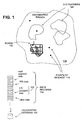
- a geographic database 100 includes data 104 that represent features that are located in a covered region 108.
- the geographic database 100 may contain data that represent roads 112 and points of interest 116.
- the geographic database 100 also includes data 120 that represent two dimensional features or entities 124.
- Some of the different kinds of two dimensional features that can be represented in the geographic database 100 include land features (e.g., mountain ranges), bodies of water (e.g., lakes, ponds, swamps, wetlands), recreation areas (e.g., golf courses, parks, stadiums, forest preserves), business parks, industrial parks, and governmental administrative areas (e.g., cities, towns, states, townships, municipalities, counties, school districts), as well as other types of areas.
- two-dimensional features are represented using polygons.
- the data that are used to represent two-dimensional features describe these features as polygons.
- the boundary of the polygon corresponds to the boundary of the represented two-dimensional feature.
- the geographic database 100 follows certain conventions. For example, links do not cross themselves and not cross each other except at a node. Also, there are no duplicated shape points, nodes or links. Two links that connect to each other have a common node. In the geographic database 100, overlapping two-dimensional geographic features are represented by overlapping polygons. When polygons overlap, the boundary of one polygon crosses the boundary of the other polygon. In the geographic database 100, the location at which the boundary of one polygon intersects the boundary of another polygon is represented by a node.
- a node may be used to represent other locations along the boundary of a polygon other than a location at which the boundary of the polygon intersects the boundary of another polygon.
- a shape point is not used to represent a point at which the boundary of a polygon intersects the boundary of another polygon.
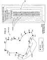
- a data representation 132 of a polygon that represents a two-dimensional feature includes a list 136 that identifies each oriented link that forms the boundary of the polygon. According to a convention used in the geographic database, the list 136 identifies the oriented links in clockwise order. If the polygon has a hole (i.e., a second polygon located entirely inside the first polygon), the hole is identified by a list of oriented links listed in counter clockwise order.
- a method for determining the intersection of polygons is described in connection with Figures 3-10.
- the method is implemented by a software program 200 that uses the geographic database 100 that contains data representations of polygons, as described in connection with Figures 1 and 2.
- the software program 200 receives two data representations of polygons as an input. (The two data representations of polygons conform to those described in Figure 2.)
- the software program 200 provides, as an output, a data representation of each polygon that represents a polygonal intersection of the two data representations of polygons that were provided as input.
- the software program 200 provides an output indicating that there is no intersection of the two data representations of polygons that were provided as input.
- the software program 200 may be installed on a navigation system 210 that uses a geographic database to provide navigation-related features to a driver of a vehicle.
- the software program 200 may also be installed on a server that uses a geographic database to provide navigation-related services to various types of users, including vehicle drivers, persons who are not drivers, users of personal digital assistants (PDAs), cell phone users, and so on.
- the server that uses the geographic database may be connected to the Internet or other communications network.
- the software program 200 may also be used when compiling a geographic database, i.e., to produce a derived database product from a source database.
- the software program 200 may also be used on a standalone computer that uses a geographic database to provide various navigation-related, map-related, or other types of features.
- the software program 200 may be stored on a computer-readable medium, loaded from the medium into a memory of the system and run, as needed.
- Figure 4 shows two polygons, labeled P(A) and P(B). Using the disclosed embodiment, the intersection, P(I), of polygons P(A) and P(B) is determined.
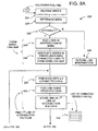
- Figures 5A-5C shows steps in a process 220 performed by the software program 200 for determining the intersections of the polygons P(A) and P(B).
- the process 220 begins with a step in which the data representations of the two polygons are received (Step 224).
- the process 220 includes a step that forms minimum bounding rectangles for the two polygons P(A) and P(B) (Step 228).
- Figure 6 depicts formation of these minimum bounding rectangles for P(A) and P(B), labeled MBR(A) and MBR(B), respectively.
- the minimum bounding rectangles, MBR(A) and MBR(B) are compared to determine whether they intersect (Step 232).
- Step 236 If the minimum bounding rectangles of P(A) and P(B) do not intersect, then the polygons P(A) and P(B) do not intersect, and a negative result is returned (Step 236). If the minimum bounding rectangles MBR(A) and MBR(B) intersect, then the polygons P(A) and P(B) may intersect and the process 220 continues.
- the process continues by forming a node-link map.
- the node-link map is formed using the polygonal intersection, MBR(A_B) of the minimum bounding rectangles MBR(A) and MBR(B) of the polygons P(A) and P(B). This polygonal intersection P(A_B) is determined as shown in Figure 6.
- each link of either polygon, P(A) or P(B) which is located entirely inside the polygonal intersection P(A_B) of the minimum bounding rectangles MBR(A) and MBR(B) of the polygons P(A) and P(B) is identified (Step 244).
- a link is located entirely inside the intersection MBR(A_B) of the minimum bounding rectangles MBR(A) and MBR(B) if both ends of the link are inside the intersection MBR(A_B) of the minimum bounding rectangles MBR(A) and MBR(B).
- each node of each of these identified links is identified. (Shape points can be ignored at this step.)
- Each of these identified nodes is then included as an entry in the node-link map (Step 248). For each node included as an entry in the node-link map, all the links that connect to the node are identified and associated with the node in the map.
- the node-link map is used to identify a node (referred to herein as "N(START)") that is located on the polygon P(I) that forms the intersection of the input polygons P(A) and P(B).
- N(START) a node that has three (or more) links associated with it.
- a node from the node-link map that has three (or more) links associated with it is located on the polygon P(I) that forms the intersection of the two polygons P(A) and P(B).
- a process is performed that identifies one link of one of the original polygons, P(A) or P(B), that is located inside the other of the original polygons, P(B) or P(A) (Step 254).
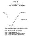
- a link of one of the original polygons that is located inside the other of the original polygons is part of the intersection polygon P(I). This link is referred to as "LINK(START)." Details of the process 400 for finding this link are illustrated in Figures 7A, 7B and 8.
- node N is the starting node since four edges are connected to it, i.e., ae1 and ae2 from P(A), be1 and be2 from P(B). If ae2 is on the right side of be1 and be2, then ae2 is inside P(B) and can be selected as the starting edge of the polygon intersection (as shown in Figure 7A). If ae1 is on the right side of be1 and be2, then ae1 is inside P(B) and can be selected as the starting edge of the polygon intersection.
- the process 500 shown in Figure 8 can be used to determine whether ae2 is on the right side of be1 and be2.
- the shape point bp1 is selected from be1
- the shape point bp2 is selected from be2
- the shape point ap2 is selected from ae2.
- These shape points are selected because they are the closest shape points on their respective edges to node N(point p) although other shape points on these edges may be selected as well.
- the process 500 in Figure 8 is used to test point if ap2 is on the right side of the line segment bp1_p and p_bp2. If so, ae2 is to the right of be1 and be2 (as shown in Figure 7A). If not, ae2 is not on the right of be1 and be2 (as shown in Figure 7B).
- the next link that forms the intersection polygon P(I) is identified. This next link is identified by examining all the links that connect to the clockwise end of the LINK(START). Referring to Figure 5B, the clockwise end of the LINK(START) is determined from the clockwise direction of the links in the original polygon (P(A) or P(B)) from which LINK(START) was taken (Step 264).
- this link i.e., the link after LINK(START)
- the process continues by determining the next link that forms the intersection polygon P(I).
- This next link is determined in a similar manner as just described. That is, all the links that connect to the clockwise end of the link are identified (Steps 264 and 272, again). If there is only one other link, then this link is added to the list of links that form the intersection polygon P(I). If there are two or more other links, then the next link is the one that forms the smallest angle in a counterclockwise direction from the link most recently identified as being part of the intersection polygon P(I) (Step 278, again).
- Step 280 The process continues until the N(START) is encountered (Step 280).
- N(START) When N(START) is encountered, then one simple polygon (that forms part or all of the entire polygon intersection P(I) of P(A) and P(B)) has been identified. Data describing this simple polygon are contained in the list 258. These data are added to a simple polygon list in a data representation 318 (in Figure 5C) of the entire intersection polygon P(I) of P(A) and P(B) (Step 284).
- Step 288 All used links and nodes in the link-node map are removed (Step 288). If there are still nodes with three or more connected links in the node-link map after a simple polygonal intersection has been identified (Step 292 in Figure 5B), then there is at least one more distinct simple polygonal intersection between the first polygon and the second polygon. The process is repeated (starting at Step 252 in Figure 5A) to determine each additional simple polygonal intersection. The process is repeated until there is no node in the link-node map that has more than three links connected to it.
- the process 220 finds intersected holes and islands in P(A) and P(B).
- Some two-dimensional features represented in the geographic database 100 are encompassed entirely within other represented two-dimensional features.
- an island is located entirely within a body of water.
- a two-dimensional feature that is encompassed entirely within another two-dimensional is represented as a hole inside a polygon.
- the data representation of the polygon containing a hole includes (1) a list of edges that define the boundary of the entire polygon (i.e., similar to Figure 2, described above) and (2) a list of edges that define the boundary of the hole located inside the polygon. According to a convention used in the geographic database 100, the list of edges in the data representation of a hole inside a polygon are ordered in counter-clockwise order.
- Figure 9 shows a polygon with a hole and data representation thereof.
- Figure 10 illustrates the intersection of two polygons having holes/islands in their intersection.
- the data representation of the polygonal intersection includes a representation of any holes of either of the original polygons that are located inside the polygonal intersection.
- a determination is made whether the minimum bounding rectangle of the hole is located inside the intersection of the minimum bounding rectangles of the two original polygons. If the minimum bounding rectangle of the hole is not located completely inside the intersection of the minimum bounding rectangles of the two original polygons, then the hole is not located in the polygonal intersection. If the minimum bounding rectangle of the hole is located inside the intersection of the minimum bounding rectangles of the two original polygons, then a determination is made whether any point (e.g., any node) of the hole is located inside the other of the polygons.
- any point e.g., any node
- Figure 5C shows steps in the process 220 for handling holes/islands in the intersection polygon, P(I).
- a search is made to find an immediate parent simple polygon in polygon B. If there is a simple polygon in B and its orientation is clockwise, then the island/hole from polygon A is a simple intersection polygon. If there is no parent polygon in B or the orientation of the parent simple polygon in B is counter clockwise, then the island/hole from polygon A is not a simple intersection polygon (Step 302). These steps are repeated until all islands/holes from polygon A have been considered.
- the process continues by considering an island/hole from polygon B and searching for an immediate parent simple polygon in polygon A. If there is a simple polygon in A and its orientation is clockwise, then the island/hole from polygon B is a simple intersection polygon. If there is no parent polygon in A or the orientation of the parent simple polygon in A is counter clockwise, then the island/hole from polygon B is not a simple intersection polygon (Step 306). This process is repeated until all islands/holes from polygon B have been visited.
- a data representation of the entire complex polygon intersection, P(I), is built from the list(s) of simple polygons list 318 (Step 307).
- the intersection of P(A) and P(B) may include one or more polygons, each of which may be either simple or complex.
- the data representation of the polygonal intersection can then used by other applications in the system in which the software program 200 is installed that require data indicating the polygonal intersection of the P(A) and P(B) (Step 288)
- a method for determining the union of polygons is described in connection with Figures 11-17.
- the method is implemented by a software program 600 that uses the geographic database 100 that contains data representations of polygons, as described in connection with Figures 1 and 2.
- the software program 600 receives two data representations of polygons as an input. (The two data representations of polygons conform to those described in Figure 2.)
- the software program 600 provides, as an output, a data representation of a polygon (i.e., the union) of the two data representations of polygons that were provided as input.
- the software program 600 is installed on a computer system 610.
- the computer system 610 may be the same computer system 210 shown in Figure 3 or may be different computer system.
- the software program 600 may be stored on a computer-readable medium, loaded from the medium into a memory of the system and run, as needed.
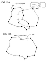
- Figure 12 shows two polygons, labeled P(A) and P(B).
- P(A) and P(B) are polygons, labeled P(A) and P(B).
- P(U) the union of polygons P(A) and P(B) is determined.
- Figures 13A-13C shows steps in a process 620 performed by the software program 600 for determining the union of the polygons P(A) and P(B).
- the process 620 begins with a step in which the data representations of the two polygons are received (Step 624).
- the process 620 includes a step that forms minimum bounding rectangles for the two polygons P(A) and P(B) (Step 628).
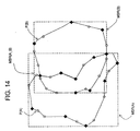
- Figure 14 depicts formation of these minimum bounding rectangles for P(A) and P(B), labeled MBR(A) and MBR(B), respectively.
- the minimum bounding rectangles, MBR(A) and MBR(B) are compared to determine whether they intersect (Step 632).
- Step 636 If the minimum bounding rectangles of P(A) and P(B) do not intersect, then there is no union between the polygons P(A) and P(B), and a negative result is returned (Step 636). If the minimum bounding rectangles MBR(A) and MBR(B) intersect (including touching), then there may be a union between the polygons P(A) and P(B) and the process 620 continues.
- the process continues by forming a node-link map.
- the node-link map is formed using the polygonal intersection, MBR(A_B) of the minimum bounding rectangles MBR(A) and MBR(B) of the polygons P(A) and P(B). This polygonal intersection P(A_B) is determined as shown in Figure 14.
- each link of either polygon, P(A) or P(B) which is located entirely inside the polygonal intersection P(A_B) of the minimum bounding rectangles MBR(A) and MBR(B) of the polygons P(A) and P(B) is identified (Step 644).
- a link is located entirely inside the intersection MBR(A_B) of the minimum bounding rectangles MBR(A) and MBR(B) if both ends of the link are inside the intersection MBR(A_B) of the minimum bounding rectangles MBR(A) and MBR(B).
- each node of each of these identified links is identified. (Shape points can be ignored at this step).
- Each of these identified nodes is then included as an entry in the node-link map (Step 648). For each node included as an entry in the node-link map, all the links that connect to the node are identified and associated with the node in the map.
- the node-link map is used to identify a node (referred to herein as "N(START)") that is located on the polygon P(U) that forms the union of the input polygons P(A) and P(B).
- N(START) a node that has three (or more) links associated with it.
- a node from the node-link map that has three (or more) links associated with it is located on the polygon P(U) that forms the union of the two polygons P(A) and P(B).
- a process is performed that identifies one link of one of the original polygons, P(A) or P(B), that is located outside the other of the original polygons, P(B) or P(A) (Step 654).
- a link of one of the original polygons that is located outside the other of the original polygons is part of the union polygon P(U) (Step 660). This link is referred to as "LINK(START)." Details of the process 697 for finding this link are illustrated in Figures 15A, 15B and 16.
- Node N is determined to be a starting node since four edges are connected to it, i.e., ae1 and ae2 from P(A), be1 and be2 from P(B). If ae1 is on the left side of be1 and be2, then ae1 is outside P(B) and can be selected as the starting edge of the polygon union (as shown in Figure 15A). If ae1 is on the left side of be1 and be2, then ae1 is outside P(B) and can be selected as the starting edge of the polygon union.
- ae2 and ae1 both are on the left side of be1 and be2, then ae1 and ae2 are outside P(B) and both can be selected as the starting edge of the polygon union (as shown in Figure 15B).
- the process 700 shown in Figure 16 can be used. Using the process 700 in Figure 16, a shape point bp1 is selected from be1, a shape point bp2 is selected from be2 and the shape point ap1 is selected from ae1. These shape points are selected because they are the closest shape points on their respective edges to node N(point p) although other shape points on these edges may be selected as well.
- the process 700 in Figure 16 is used to test if point ap1 is on the left side of the line segment bp1_p and p_bp2. If so, ae1 is to the left of be1 and be2 (as shown in Figure 15A), and therefore, is on the outside of P(B).
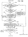
- the next link that forms the union polygon P(U) is identified. This next link is identified by examining all the links that connect to the non-referenced end of LINK(START). Referring to Figure 13B, the non-referenced end of the LINK(START) is determined by polygon construction convention (clockwise for island, counter-clockwise for hole, Step 664).
- this link i.e., the link after LINK(START)
- the process continues by determining the next link that forms the union polygon P(U).
- This next link is determined in a similar manner as just described. That is, all the links that connect to the non-referenced end of the link are identified (Steps 664 and 672, again). If there is only one other link, then this link is added to the list of links that form the union polygon P(U). If there are two or more other links, then the next link is the one that forms the largest angle in a counterclockwise direction from the link most recently identified as being part of the union polygon P(U) (Step 678, again).
- Step 680 the process continues until the N(START) is encountered.
- N(START) When N(START) is encountered, then one simple polygon (that forms part or all of the entire polygon union P(U) of P(A) and P(B)) has been identified. Data describing this simple polygon are contained in the list 658. These data are added to a simple polygon list in a data representation 718 (in Figure 13C) of the entire union polygon P(U) of P(A) and P(B) (Step 684).
- Step 688 All used links and nodes in the link-node map are removed (Step 688). If there are still nodes with three or more connected links in the node-link map after a simple polygonal union has been identified (Step 692 in Figure 13B), then there is at least one more distinct simple polygonal union between the first polygon and the second polygon. The process is repeated (starting at Step 652 in Figure 13A) to determine each additional simple polygonal union. The process is repeated until there is no node in the link-node map that has more than three links connected to it.
- the process 620 finds unionized holes and islands in P(A) and P(B). Holes and islands in polygons were described above in connection with Figure 9.
- Figure 17 illustrates the union of two polygons having holes/islands in their union.
- the data representation of the polygonal union includes a representation of any holes of either of the original polygons that are located inside the polygonal union.
- a determination is made whether the minimum bounding rectangle of the hole is located outside the intersection of the minimum bounding rectangles of the two original polygons. If the minimum bounding rectangle of the hole is not located completely inside the union of the minimum bounding rectangles of the two original polygons, then the hole is located in the polygonal union. If the minimum bounding rectangle of the hole is located inside the intersection of the minimum bounding rectangles of the two original polygons, then a determination is made whether any point (e.g., any node) of the hole is located inside the other of the polygons.
- any point e.g., any node
- Figure 13C shows steps in the process 620 for handling holes/islands in the union polygon, P(U).
- a search is made to find an immediate parent simple polygon in polygon B. If there is no parent polygon in B or if there is an immediate parent simple polygon in B and its orientation is counter-clockwise, then the island/hole from polygon A is a simple union polygon. If the orientation of the parent simple polygon in B is clockwise, then the island/hole from polygon A is not a simple union polygon (Step 702). These steps are repeated until all islands/holes from polygon A have been considered.
- the process continues by considering an island/hole from polygon B and searching for an immediate parent simple polygon in polygon A. If there is no parent polygon in A or if there is a simple polygon in A and its orientation is counter-clockwise, then the island/hole from polygon B is a simple union polygon. If the orientation of the parent simple polygon in A is clockwise, then the island/hole from polygon B is not a simple union polygon (Step 706). This process is repeated until all islands/holes from polygon B have been visited.
- P(A) has four holes, a2, a3, a4, a6 and one island a5 located inside of a4.
- P(B) has three holes, b2, b3, b4.
- a3, a4 are not in P(B) and therefore are considered as unionized holes.
- a4, a6, a5 are in P(B) and therefore are not considered as unionized holes.
- b2, b4 are not in P(A), and therefore are considered as unionized holes.
- b3 is in P(A) and therefore is not considered as a unionized hole.
- a data representation of the entire complex polygon union, P(U) is built from the list(s) of simple polygons 718 (Step 707).
- the union of P(A) and P(B) may be either simple or complex.
- the data representation P(U) can be used by other applications that need to have information about the union of P(A) and P(B).
- the present methods for determining the intersection and union of polygons and for constructing polygons are computationally less intensive than prior methods.
- the present methods achieve this advantage, in part, because only the polygon edges are considered instead of entire line segments, therefore greatly reducing the amount of computation.
- the data representations of polygons included lists of links used to represent the boundaries of the polygons and that the links contained on a list were ordered corresponding to a clockwise traversal of the represented polygon boundary via the links. It is not required that the lists of links used to represent polygons identify the links in clockwise order so long as the order in which the links are listed is consistent throughout the geographic database.
- data representations of polygons instead of listing the links that form polygon boundaries in a clockwise order, could list the links in a counterclockwise order. If a counterclockwise order is used for polygon boundaries, it might be preferable to use a clockwise order to represent holes in polygons.
Landscapes
- Engineering & Computer Science (AREA)
- Physics & Mathematics (AREA)
- Geometry (AREA)
- Software Systems (AREA)
- Remote Sensing (AREA)
- Computer Graphics (AREA)
- General Physics & Mathematics (AREA)
- Theoretical Computer Science (AREA)
- Processing Or Creating Images (AREA)
- Instructional Devices (AREA)
- Image Analysis (AREA)
- Navigation (AREA)
- Image Generation (AREA)
- Measurement Of Mechanical Vibrations Or Ultrasonic Waves (AREA)
- Gyroscopes (AREA)
- Purification Treatments By Anaerobic Or Anaerobic And Aerobic Bacteria Or Animals (AREA)
Claims (18)
- Procédé de détermination d'une intersection polygonale (P(I)) d'un premier polygone (P(A)) et d'un deuxième polygone (P(B)), comprenant :au niveau d'une intersection d'une frontière du premier polygone avec une frontière du deuxième polygone, le fait de déterminer une première partie connue d'une frontière de l'intersection polygonale telle que composée d'une partie de la frontière du premier polygone qui est située à l'intérieur du deuxième polygone ; etle fait de déterminer chaque partie suivante de la frontière de l'intersection polygonale qui est reliée à une partie connue actuelle de la frontière de l'intersection polygonale en sélectionnant la partie de la frontière du premier polygone ou du deuxième polygone qui est reliée à une extrémité d'attaque de la partie connue actuelle de la frontière de l'intersection polygonale et qui forme un angle de rotation minimal avec celle-ci.
- Procédé selon la revendication 1, dans lequel le premier polygone, le deuxième polygone et l'intersection polygonale sont représentés par des données indiquant une liste de bords.
- Procédé selon la revendication 1, dans lequel la partie de la frontière du premier polygone qui est située à l'intérieur du deuxième polygone est déterminée en comparant des angles formés par la partie de la frontière du premier polygone avec des parties de la frontière du deuxième polygone formées par l'intersection.
- Procédé selon la revendication 1, comprenant en outre :le fait de déterminer une intersection polygonale supplémentaire du premier polygone et du deuxième polygone en effectuant les étapes de détermination pour toute intersection supplémentaire de la frontière du premier polygone avec la frontière du deuxième polygone qui ne fait pas déjà partie de l'intersection polygonale d'un premier polygone et d'un deuxième polygone déjà déterminée.
- Procédé de détermination d'une union polygonale (P(U)) d'un premier polygone (P(A)) et d'un deuxième polygone (P(B)), comprenant :au niveau d'une intersection d'une frontière du premier polygone avec une frontière du deuxième polygone, le fait de déterminer une première partie connue d'une frontière de l'union polygonale telle que composée d'une partie de la frontière du premier polygone qui est située à l'extérieur du deuxième polygone ; etle fait de déterminer chaque partie suivante de la frontière de l'union polygonale qui est reliée à une partie connue actuelle de la frontière de l'union polygonale en sélectionnant la partie de la frontière du premier polygone ou du deuxième polygone qui est reliée à une extrémité d'attaque de la partie connue actuelle de la frontière de l'union polygonale et qui forme un angle de rotation maximal avec celle-ci.
- Procédé selon la revendication 5, dans lequel le premier polygone, le deuxième polygone et l'union polygonale sont représentés par des données indiquant une liste de bords.
- Procédé selon la revendication 2 ou la revendication 6, dans lequel les bords représentent les frontières des polygones.
- Procédé selon la revendication 2 ou la revendication 6, dans lequel les bords dans la liste de bords sont systématiquement ordonnés dans le sens des aiguilles d'une montre ou dans le sens inverse des aiguilles d'une montre.
- Procédé selon la revendication 2 ou la revendication 6, dans lequel un trou situé dans le premier polygone est représenté par des données indiquant une liste de bords.
- Procédé selon la revendication 9, dans lequel les bords dans la liste de bords qui représentent un trou sont ordonnés dans une direction opposée à la direction utilisée pour ordonner les bords dans la liste de bords utilisés pour représenter le premier polygone.
- Procédé selon la revendication 2 ou la revendication 6, dans lequel les bords dans la liste de bords sont systématiquement ordonnés dans le sens des aiguilles d'une montre.
- Procédé selon la revendication 1 ou la revendication 5, dans lequel le premier polygone et le deuxième polygone représentent des caractéristiques géographiques en deux dimensions.
- Procédé selon la revendication 5, dans lequel la partie de la frontière du premier polygone qui est située à l'extérieur du deuxième polygone est déterminée en comparant des angles formés par la partie de la frontière du premier polygone avec des parties de la frontière du deuxième polygone formées par l'intersection.
- Procédé selon la revendication 1 ou la revendication 5, dans lequel l'intersection de la frontière du premier polygone avec la frontière du deuxième polygone est trouvée en cherchant une zone rectangulaire formée par une intersection d'un premier rectangle de délimitation minimum englobant le premier polygone et d'un deuxième rectangle de délimitation minimum englobant le deuxième polygone.
- Procédé selon la revendication 1 ou la revendication 5, dans lequel les étapes de détermination sont effectuées sur un serveur connecté à l'Internet, le procédé comprenant l'étape consistant à fournir à des utilisateurs des services liés à la navigation.
- Programme qui, lorsqu'il est exécuté par un ordinateur, effectue un procédé selon l'une quelconque des revendications 1 à 15.
- Programme selon la revendication 16, dans lequel le programme utilise une base de données géographiques contenant des représentations de données du premier polygone et du deuxième polygone.
- Appareil adapté pour effectuer un procédé selon l'une quelconque des revendications 1 à 15.
Applications Claiming Priority (4)
| Application Number | Priority Date | Filing Date | Title |
|---|---|---|---|
| US09/929,397 US6917877B2 (en) | 2001-08-14 | 2001-08-14 | Method for determining the intersection of polygons used to represent geographic features |
| US929397 | 2001-08-14 | ||
| US94550401A | 2001-08-30 | 2001-08-30 | |
| US945504 | 2001-08-30 |
Publications (3)
| Publication Number | Publication Date |
|---|---|
| EP1291823A2 EP1291823A2 (fr) | 2003-03-12 |
| EP1291823A3 EP1291823A3 (fr) | 2004-12-15 |
| EP1291823B1 true EP1291823B1 (fr) | 2006-05-03 |
Family
ID=27129975
Family Applications (1)
| Application Number | Title | Priority Date | Filing Date |
|---|---|---|---|
| EP02255634A Expired - Lifetime EP1291823B1 (fr) | 2001-08-14 | 2002-08-13 | Méthode pour déterminer les intersections |
Country Status (5)
| Country | Link |
|---|---|
| US (1) | US6917877B2 (fr) |
| EP (1) | EP1291823B1 (fr) |
| JP (1) | JP4477818B2 (fr) |
| AT (1) | ATE325401T1 (fr) |
| DE (1) | DE60211086T2 (fr) |
Families Citing this family (27)
| Publication number | Priority date | Publication date | Assignee | Title |
|---|---|---|---|---|
| US6801850B1 (en) * | 2000-10-30 | 2004-10-05 | University Of Illionis - Chicago | Method and system for tracking moving objects |
| JP4580209B2 (ja) * | 2004-10-18 | 2010-11-10 | クラリオン株式会社 | 要約地図作成装置 |
| KR100657937B1 (ko) * | 2004-12-14 | 2006-12-14 | 삼성전자주식회사 | 2차원 선형 데이터의 실시간 3차원 변환 방법 및 장치,그리고 이를 이용한 2차원 선형 데이터의 실시간 3차원시각화 방법 및 장치 |
| KR100634536B1 (ko) * | 2005-01-25 | 2006-10-13 | 삼성전자주식회사 | 3차원 그래픽스 환경에서의 2차원 고가도로 데이터의 3차원 변환 방법 및 장치, 그리고 이를 이용한 3차원 그래픽스 환경에서의 2차원 고가도로 데이터의 3차원 시각화 방법 및 장치 |
| US7856366B2 (en) * | 2005-09-30 | 2010-12-21 | International Business Machines Corporation | Multiple accounts for health record bank |
| US20070078687A1 (en) * | 2005-09-30 | 2007-04-05 | International Business Machines Corporation | Managing electronic health records within a wide area care provider domain |
| US8620688B2 (en) * | 2005-09-30 | 2013-12-31 | International Business Machines Corporation | Checkbook to control access to health record bank account |
| US8423382B2 (en) * | 2005-09-30 | 2013-04-16 | International Business Machines Corporation | Electronic health record transaction monitoring |
| JP4311391B2 (ja) | 2005-10-03 | 2009-08-12 | ソニー株式会社 | 接触形状算出装置及び接触形状算出方法、並びにコンピュータ・プログラム |
| US20070150315A1 (en) * | 2005-12-22 | 2007-06-28 | International Business Machines Corporation | Policy driven access to electronic healthcare records |
| US20080051989A1 (en) * | 2006-08-25 | 2008-02-28 | Microsoft Corporation | Filtering of data layered on mapping applications |
| US8228326B2 (en) * | 2007-10-03 | 2012-07-24 | Oracle International Corporation | Three dimensional surface and solid query processing |
| JP4739309B2 (ja) * | 2007-11-09 | 2011-08-03 | 株式会社リコー | 情報処理装置、及び情報処理方法 |
| US20090254841A1 (en) * | 2007-11-12 | 2009-10-08 | Move Sales, Inc. | Apparatus, method, and computer program product for characterizing user-defined areas |
| US20090132469A1 (en) * | 2007-11-16 | 2009-05-21 | Urban Mapping, Inc. | Geocoding based on neighborhoods and other uniquely defined informal spaces or geographical regions |
| US8115320B2 (en) * | 2008-05-29 | 2012-02-14 | United Microelectronics Corp. | Bond pad structure located over active circuit structure |
| US8121415B2 (en) * | 2008-10-28 | 2012-02-21 | Quality Vision International, Inc. | Combining feature boundaries |
| US8275800B1 (en) * | 2010-08-05 | 2012-09-25 | Teradata Us, Inc. | Splitting polygons with interior rings |
| US20140067483A1 (en) * | 2012-08-30 | 2014-03-06 | Electronics And Telecommunications Research Institute | Apparatus and method for constructing radar chart |
| CN103473984B (zh) * | 2013-08-14 | 2015-05-27 | 中国地质大学(武汉) | 网络环境下基于模板的动态地图获取方法 |
| US10248731B1 (en) * | 2014-05-16 | 2019-04-02 | Corelogic Solutions, Llc | System and method for linking data records for parcels |
| US9740719B2 (en) | 2014-07-07 | 2017-08-22 | Sap Se | Column store optimization using telescope columns |
| US10593074B1 (en) * | 2016-03-16 | 2020-03-17 | Liberty Mutual Insurance Company | Interactive user interface for displaying geographic boundaries |
| EP3438936B1 (fr) | 2017-08-04 | 2022-03-30 | NXP USA, Inc. | Procédé et appareil de gestion de couches graphiques dans un système de traitement de données |
| EP3438965A1 (fr) | 2017-08-04 | 2019-02-06 | NXP USA, Inc. | Procédé et appareil de mélange de couches dans un composant d'affichage graphique |
| JP7143503B2 (ja) * | 2019-02-28 | 2022-09-28 | 株式会社東芝 | 情報処理装置、情報処理方法、およびプログラム |
| CN113706604B (zh) * | 2021-08-20 | 2024-02-09 | 园测信息科技股份有限公司 | 一种基于两个凸多边形交集求解算法的地类图斑分析方法 |
Family Cites Families (17)
| Publication number | Priority date | Publication date | Assignee | Title |
|---|---|---|---|---|
| US4694404A (en) | 1984-01-12 | 1987-09-15 | Key Bank N.A. | High-speed image generation of complex solid objects using octree encoding |
| CA1277043C (fr) | 1985-07-25 | 1990-11-27 | Marvin S. White, Jr. | Appareil stockant une representation de structures topologiques et methodes de construction et d'exploration de cette representation |
| JPH077456B2 (ja) * | 1988-11-11 | 1995-01-30 | 大日本スクリーン製造株式会社 | 重合度による図形の認識装置 |
| US5347619A (en) | 1991-04-30 | 1994-09-13 | International Business Machines Corporation | Nonconvex polygon identifier |
| JP3332165B2 (ja) | 1992-08-08 | 2002-10-07 | 株式会社リコー | 画像処理装置 |
| JPH06223201A (ja) | 1993-01-22 | 1994-08-12 | Matsushita Electric Ind Co Ltd | 並列画像生成装置 |
| JP2710202B2 (ja) | 1993-03-24 | 1998-02-10 | インターナショナル・ビジネス・マシーンズ・コーポレイション | 閉じた輪郭イメージを凸多角形で境界づける方法及びデータ処理装置 |
| US5613052A (en) | 1993-09-02 | 1997-03-18 | International Business Machines Corporation | Method and apparatus for clipping and determining color factors for polygons |
| SG75807A1 (en) | 1996-01-11 | 2000-10-24 | Sony Corp | Signal transmitting method and apparatus |
| US5990896A (en) | 1996-09-30 | 1999-11-23 | Mitsubishi Electric Information Technology Center America, Inc. (Ita) | Rapid and efficient terrain surface finding system |
| US5961572A (en) * | 1997-04-01 | 1999-10-05 | Bellsouth Intellectual Property Corporation | System and method for identifying the geographic region of a geographic area which contains a geographic point associated with a location |
| US5818460A (en) | 1997-05-08 | 1998-10-06 | Autodesk, Inc. | Method for performing polygon set operations on polygonal regions |
| US6215503B1 (en) | 1998-05-29 | 2001-04-10 | Microsoft Corporation | Image generator and method for resolving non-binary cyclic occlusions with image compositing operations |
| US6163749A (en) | 1998-06-05 | 2000-12-19 | Navigation Technologies Corp. | Method and system for scrolling a map display in a navigation application |
| EP1182611A4 (fr) * | 1999-01-25 | 2003-04-02 | Kabushiki Kaisya Zenrin | Dispositif et procede de creation et d'utilisation de donnees sur une carte routiere exprimees par des polygones |
| US6208352B1 (en) | 1999-08-30 | 2001-03-27 | General Dynamics Government Systems Corp. | Method for the computerized solution of the intersection of polygons |
| JP3471003B2 (ja) * | 2000-02-02 | 2003-11-25 | 松下電器産業株式会社 | 交差点表示方法およびその地図表示装置並びに記録媒体 |
-
2001
- 2001-08-14 US US09/929,397 patent/US6917877B2/en not_active Expired - Fee Related
-
2002
- 2002-08-13 EP EP02255634A patent/EP1291823B1/fr not_active Expired - Lifetime
- 2002-08-13 AT AT02255634T patent/ATE325401T1/de not_active IP Right Cessation
- 2002-08-13 DE DE60211086T patent/DE60211086T2/de not_active Expired - Lifetime
- 2002-08-14 JP JP2002272286A patent/JP4477818B2/ja not_active Expired - Lifetime
Also Published As
| Publication number | Publication date |
|---|---|
| DE60211086T2 (de) | 2006-10-12 |
| US6917877B2 (en) | 2005-07-12 |
| ATE325401T1 (de) | 2006-06-15 |
| JP4477818B2 (ja) | 2010-06-09 |
| US20030037059A1 (en) | 2003-02-20 |
| EP1291823A3 (fr) | 2004-12-15 |
| JP2003186390A (ja) | 2003-07-04 |
| DE60211086D1 (de) | 2006-06-08 |
| EP1291823A2 (fr) | 2003-03-12 |
Similar Documents
| Publication | Publication Date | Title |
|---|---|---|
| EP1291823B1 (fr) | Méthode pour déterminer les intersections | |
| US5729458A (en) | Cost zones | |
| DE60028143T2 (de) | Verfahren zur Erzeugung einer durch ein Navigationssystem berechneten Vorschauroute | |
| US5638280A (en) | Vehicle navigation apparatus and method | |
| EP3109842B1 (fr) | Procédé et dispositif de mise en correspondance de carte centré sur la carte | |
| Golledge et al. | A conceptual model and empirical analysis of children's acquisition of spatial knowledge | |
| JP4875240B2 (ja) | ポリゴン道路ネットワークデータ作成装置、道路地図表示装置及び方法 | |
| EP1955242B1 (fr) | Cartes de destination schématiques | |
| EP0838662B1 (fr) | Système de navigation | |
| EP1398599A1 (fr) | Procédé de représentation rationalisée de routes dans une base de données géographique | |
| EP1917643B1 (fr) | Generalisation de caracteristiques dans une carte numerique | |
| US6188955B1 (en) | Method and apparatus for storing cartographic route data | |
| EP1367368B1 (fr) | Données de direction pour guidage routier | |
| EP4202365A1 (fr) | Procédé, appareil et produit de programme informatique pour identifier et corriger une géométrie de voie dans des données cartographiques | |
| EP4202364A1 (fr) | Procédé, appareil et produit de programme informatique pour identifier et corriger une géométrie de voie d'intersection dans des données cartographiques | |
| EP1547020B1 (fr) | Maillage irregulier et description geometrique a plongement dans un systeme infographique | |
| EP1538569A2 (fr) | Procédé d'écrêtage des lignes et procédé d'affichage d'une image tridimensionnelle en utilisant un tel procédé | |
| US12013255B2 (en) | Method, apparatus, and computer program product for correcting lane geometry in map data | |
| Tomko | Destination descriptions in urban environments | |
| EP1293935A2 (fr) | Méthode de contruction de caractéristiques géographiques par polygônes | |
| Dunkars | Multiple representation databases for topographic information | |
| JP2003065787A (ja) | 区分的線形補間を用いる距離計算方法 | |
| JPH08178682A (ja) | 経路探索方法及び経路探索装置 | |
| JP2000337902A (ja) | ナビゲーション装置 | |
| So et al. | Sketch map generation method using leveled spatial indexing technique in a mobile environment |
Legal Events
| Date | Code | Title | Description |
|---|---|---|---|
| PUAI | Public reference made under article 153(3) epc to a published international application that has entered the european phase |
Free format text: ORIGINAL CODE: 0009012 |
|
| AK | Designated contracting states |
Kind code of ref document: A2 Designated state(s): AT BE BG CH CY CZ DE DK EE ES FI FR GB GR IE IT LI LU MC NL PT SE SK TR |
|
| AX | Request for extension of the european patent |
Extension state: AL LT LV MK RO SI |
|
| PUAL | Search report despatched |
Free format text: ORIGINAL CODE: 0009013 |
|
| AK | Designated contracting states |
Kind code of ref document: A3 Designated state(s): AT BE BG CH CY CZ DE DK EE ES FI FR GB GR IE IT LI LU MC NL PT SE SK TR |
|
| AX | Request for extension of the european patent |
Extension state: AL LT LV MK RO SI |
|
| RIC1 | Information provided on ipc code assigned before grant |
Ipc: 7G 06T 17/50 A |
|
| RAP1 | Party data changed (applicant data changed or rights of an application transferred) |
Owner name: NAVTEQ NORTH AMERICA, LLC |
|
| 17P | Request for examination filed |
Effective date: 20050405 |
|
| 17Q | First examination report despatched |
Effective date: 20050517 |
|
| AKX | Designation fees paid |
Designated state(s): AT BE BG CH CY CZ DE DK EE ES FI FR GB GR IE IT LI LU MC NL PT SE SK TR |
|
| GRAP | Despatch of communication of intention to grant a patent |
Free format text: ORIGINAL CODE: EPIDOSNIGR1 |
|
| RTI1 | Title (correction) |
Free format text: METHOD FOR DETERMINING INTERSECTIONS |
|
| GRAS | Grant fee paid |
Free format text: ORIGINAL CODE: EPIDOSNIGR3 |
|
| GRAA | (expected) grant |
Free format text: ORIGINAL CODE: 0009210 |
|
| AK | Designated contracting states |
Kind code of ref document: B1 Designated state(s): AT BE BG CH CY CZ DE DK EE ES FI FR GB GR IE IT LI LU MC NL PT SE SK TR |
|
| PG25 | Lapsed in a contracting state [announced via postgrant information from national office to epo] |
Ref country code: IT Free format text: LAPSE BECAUSE OF FAILURE TO SUBMIT A TRANSLATION OF THE DESCRIPTION OR TO PAY THE FEE WITHIN THE PRESCRIBED TIME-LIMIT;WARNING: LAPSES OF ITALIAN PATENTS WITH EFFECTIVE DATE BEFORE 2007 MAY HAVE OCCURRED AT ANY TIME BEFORE 2007. THE CORRECT EFFECTIVE DATE MAY BE DIFFERENT FROM THE ONE RECORDED. Effective date: 20060503 Ref country code: FI Free format text: LAPSE BECAUSE OF FAILURE TO SUBMIT A TRANSLATION OF THE DESCRIPTION OR TO PAY THE FEE WITHIN THE PRESCRIBED TIME-LIMIT Effective date: 20060503 Ref country code: SK Free format text: LAPSE BECAUSE OF FAILURE TO SUBMIT A TRANSLATION OF THE DESCRIPTION OR TO PAY THE FEE WITHIN THE PRESCRIBED TIME-LIMIT Effective date: 20060503 Ref country code: LI Free format text: LAPSE BECAUSE OF FAILURE TO SUBMIT A TRANSLATION OF THE DESCRIPTION OR TO PAY THE FEE WITHIN THE PRESCRIBED TIME-LIMIT Effective date: 20060503 Ref country code: CH Free format text: LAPSE BECAUSE OF FAILURE TO SUBMIT A TRANSLATION OF THE DESCRIPTION OR TO PAY THE FEE WITHIN THE PRESCRIBED TIME-LIMIT Effective date: 20060503 Ref country code: CZ Free format text: LAPSE BECAUSE OF FAILURE TO SUBMIT A TRANSLATION OF THE DESCRIPTION OR TO PAY THE FEE WITHIN THE PRESCRIBED TIME-LIMIT Effective date: 20060503 Ref country code: BE Free format text: LAPSE BECAUSE OF FAILURE TO SUBMIT A TRANSLATION OF THE DESCRIPTION OR TO PAY THE FEE WITHIN THE PRESCRIBED TIME-LIMIT Effective date: 20060503 Ref country code: NL Free format text: LAPSE BECAUSE OF FAILURE TO SUBMIT A TRANSLATION OF THE DESCRIPTION OR TO PAY THE FEE WITHIN THE PRESCRIBED TIME-LIMIT Effective date: 20060503 Ref country code: AT Free format text: LAPSE BECAUSE OF FAILURE TO SUBMIT A TRANSLATION OF THE DESCRIPTION OR TO PAY THE FEE WITHIN THE PRESCRIBED TIME-LIMIT Effective date: 20060503 |
|
| REG | Reference to a national code |
Ref country code: GB Ref legal event code: FG4D |
|
| REG | Reference to a national code |
Ref country code: CH Ref legal event code: EP |
|
| REF | Corresponds to: |
Ref document number: 60211086 Country of ref document: DE Date of ref document: 20060608 Kind code of ref document: P |
|
| REG | Reference to a national code |
Ref country code: IE Ref legal event code: FG4D |
|
| PG25 | Lapsed in a contracting state [announced via postgrant information from national office to epo] |
Ref country code: SE Free format text: LAPSE BECAUSE OF FAILURE TO SUBMIT A TRANSLATION OF THE DESCRIPTION OR TO PAY THE FEE WITHIN THE PRESCRIBED TIME-LIMIT Effective date: 20060803 Ref country code: DK Free format text: LAPSE BECAUSE OF FAILURE TO SUBMIT A TRANSLATION OF THE DESCRIPTION OR TO PAY THE FEE WITHIN THE PRESCRIBED TIME-LIMIT Effective date: 20060803 |
|
| PG25 | Lapsed in a contracting state [announced via postgrant information from national office to epo] |
Ref country code: ES Free format text: LAPSE BECAUSE OF FAILURE TO SUBMIT A TRANSLATION OF THE DESCRIPTION OR TO PAY THE FEE WITHIN THE PRESCRIBED TIME-LIMIT Effective date: 20060814 Ref country code: IE Free format text: LAPSE BECAUSE OF NON-PAYMENT OF DUE FEES Effective date: 20060814 |
|
| PG25 | Lapsed in a contracting state [announced via postgrant information from national office to epo] |
Ref country code: MC Free format text: LAPSE BECAUSE OF NON-PAYMENT OF DUE FEES Effective date: 20060831 |
|
| PG25 | Lapsed in a contracting state [announced via postgrant information from national office to epo] |
Ref country code: PT Free format text: LAPSE BECAUSE OF FAILURE TO SUBMIT A TRANSLATION OF THE DESCRIPTION OR TO PAY THE FEE WITHIN THE PRESCRIBED TIME-LIMIT Effective date: 20061003 |
|
| NLV1 | Nl: lapsed or annulled due to failure to fulfill the requirements of art. 29p and 29m of the patents act | ||
| REG | Reference to a national code |
Ref country code: CH Ref legal event code: PL |
|
| ET | Fr: translation filed | ||
| PLBE | No opposition filed within time limit |
Free format text: ORIGINAL CODE: 0009261 |
|
| STAA | Information on the status of an ep patent application or granted ep patent |
Free format text: STATUS: NO OPPOSITION FILED WITHIN TIME LIMIT |
|
| 26N | No opposition filed |
Effective date: 20070206 |
|
| GBPC | Gb: european patent ceased through non-payment of renewal fee |
Effective date: 20060813 |
|
| PG25 | Lapsed in a contracting state [announced via postgrant information from national office to epo] |
Ref country code: GB Free format text: LAPSE BECAUSE OF NON-PAYMENT OF DUE FEES Effective date: 20060813 |
|
| PG25 | Lapsed in a contracting state [announced via postgrant information from national office to epo] |
Ref country code: GR Free format text: LAPSE BECAUSE OF FAILURE TO SUBMIT A TRANSLATION OF THE DESCRIPTION OR TO PAY THE FEE WITHIN THE PRESCRIBED TIME-LIMIT Effective date: 20060804 |
|
| PG25 | Lapsed in a contracting state [announced via postgrant information from national office to epo] |
Ref country code: EE Free format text: LAPSE BECAUSE OF FAILURE TO SUBMIT A TRANSLATION OF THE DESCRIPTION OR TO PAY THE FEE WITHIN THE PRESCRIBED TIME-LIMIT Effective date: 20060503 Ref country code: BG Free format text: LAPSE BECAUSE OF FAILURE TO SUBMIT A TRANSLATION OF THE DESCRIPTION OR TO PAY THE FEE WITHIN THE PRESCRIBED TIME-LIMIT Effective date: 20060803 |
|
| PG25 | Lapsed in a contracting state [announced via postgrant information from national office to epo] |
Ref country code: TR Free format text: LAPSE BECAUSE OF FAILURE TO SUBMIT A TRANSLATION OF THE DESCRIPTION OR TO PAY THE FEE WITHIN THE PRESCRIBED TIME-LIMIT Effective date: 20060503 Ref country code: LU Free format text: LAPSE BECAUSE OF NON-PAYMENT OF DUE FEES Effective date: 20060813 |
|
| PG25 | Lapsed in a contracting state [announced via postgrant information from national office to epo] |
Ref country code: CY Free format text: LAPSE BECAUSE OF FAILURE TO SUBMIT A TRANSLATION OF THE DESCRIPTION OR TO PAY THE FEE WITHIN THE PRESCRIBED TIME-LIMIT Effective date: 20060503 |
|
| PGFP | Annual fee paid to national office [announced via postgrant information from national office to epo] |
Ref country code: DE Payment date: 20120827 Year of fee payment: 11 Ref country code: FR Payment date: 20120919 Year of fee payment: 11 |
|
| REG | Reference to a national code |
Ref country code: DE Ref legal event code: R119 Ref document number: 60211086 Country of ref document: DE |
|
| PG25 | Lapsed in a contracting state [announced via postgrant information from national office to epo] |
Ref country code: DE Free format text: LAPSE BECAUSE OF NON-PAYMENT OF DUE FEES Effective date: 20140301 |
|
| REG | Reference to a national code |
Ref country code: FR Ref legal event code: ST Effective date: 20140430 |
|
| PG25 | Lapsed in a contracting state [announced via postgrant information from national office to epo] |
Ref country code: FR Free format text: LAPSE BECAUSE OF NON-PAYMENT OF DUE FEES Effective date: 20130902 |
|
| REG | Reference to a national code |
Ref country code: DE Ref legal event code: R079 Ref document number: 60211086 Country of ref document: DE Free format text: PREVIOUS MAIN CLASS: G06T0017500000 Ipc: G06T0017050000 |
|
| REG | Reference to a national code |
Ref country code: DE Ref legal event code: R079 Ref document number: 60211086 Country of ref document: DE Free format text: PREVIOUS MAIN CLASS: G06T0017500000 Ipc: G06T0017050000 Effective date: 20141106 Ref country code: DE Ref legal event code: R119 Ref document number: 60211086 Country of ref document: DE Effective date: 20140301 |