EP1293144A2 - Etui plat pour objets d'utilisation courante ou de consommation - Google Patents
Etui plat pour objets d'utilisation courante ou de consommation Download PDFInfo
- Publication number
- EP1293144A2 EP1293144A2 EP02028246A EP02028246A EP1293144A2 EP 1293144 A2 EP1293144 A2 EP 1293144A2 EP 02028246 A EP02028246 A EP 02028246A EP 02028246 A EP02028246 A EP 02028246A EP 1293144 A2 EP1293144 A2 EP 1293144A2
- Authority
- EP
- European Patent Office
- Prior art keywords
- plate
- base
- cover plate
- webs
- groove
- Prior art date
- Legal status (The legal status is an assumption and is not a legal conclusion. Google has not performed a legal analysis and makes no representation as to the accuracy of the status listed.)
- Granted
Links
- 230000003203 everyday effect Effects 0.000 claims description 9
- 239000000853 adhesive Substances 0.000 claims description 7
- 230000001070 adhesive effect Effects 0.000 claims description 7
- 238000013461 design Methods 0.000 claims description 7
- 238000007373 indentation Methods 0.000 claims description 7
- 229910052751 metal Inorganic materials 0.000 claims description 4
- 239000002184 metal Substances 0.000 claims description 4
- 230000002354 daily effect Effects 0.000 claims description 3
- 230000003746 surface roughness Effects 0.000 claims description 3
- 230000007423 decrease Effects 0.000 claims 1
- 239000011521 glass Substances 0.000 claims 1
- 235000010585 Ammi visnaga Nutrition 0.000 description 21
- 244000153158 Ammi visnaga Species 0.000 description 21
- 238000003780 insertion Methods 0.000 description 9
- 230000037431 insertion Effects 0.000 description 9
- 238000012549 training Methods 0.000 description 8
- 239000000463 material Substances 0.000 description 7
- 238000003466 welding Methods 0.000 description 6
- 230000015572 biosynthetic process Effects 0.000 description 5
- 238000004519 manufacturing process Methods 0.000 description 5
- 230000004308 accommodation Effects 0.000 description 4
- 238000001746 injection moulding Methods 0.000 description 4
- 239000010410 layer Substances 0.000 description 4
- 229940112822 chewing gum Drugs 0.000 description 3
- 235000015218 chewing gum Nutrition 0.000 description 3
- 238000011161 development Methods 0.000 description 3
- 230000018109 developmental process Effects 0.000 description 3
- 238000000034 method Methods 0.000 description 3
- 238000003860 storage Methods 0.000 description 3
- DJQYKWDYUQPOOE-OGRLCSSISA-N (2s,3s)-2-[4-[(1s)-1-amino-3-methylbutyl]triazol-1-yl]-1-[4-[4-[4-[(2s,3s)-2-[4-[(1s)-1-amino-3-methylbutyl]triazol-1-yl]-3-methylpentanoyl]piperazin-1-yl]-6-[2-[2-(2-prop-2-ynoxyethoxy)ethoxy]ethylamino]-1,3,5-triazin-2-yl]piperazin-1-yl]-3-methylpentan- Chemical compound Cl.N1([C@@H]([C@@H](C)CC)C(=O)N2CCN(CC2)C=2N=C(NCCOCCOCCOCC#C)N=C(N=2)N2CCN(CC2)C(=O)[C@H]([C@@H](C)CC)N2N=NC(=C2)[C@@H](N)CC(C)C)C=C([C@@H](N)CC(C)C)N=N1 DJQYKWDYUQPOOE-OGRLCSSISA-N 0.000 description 2
- 238000002347 injection Methods 0.000 description 2
- 239000007924 injection Substances 0.000 description 2
- 238000005259 measurement Methods 0.000 description 2
- 239000000243 solution Substances 0.000 description 2
- 230000003313 weakening effect Effects 0.000 description 2
- 238000004026 adhesive bonding Methods 0.000 description 1
- 239000012790 adhesive layer Substances 0.000 description 1
- 229910052782 aluminium Inorganic materials 0.000 description 1
- XAGFODPZIPBFFR-UHFFFAOYSA-N aluminium Chemical compound [Al] XAGFODPZIPBFFR-UHFFFAOYSA-N 0.000 description 1
- 238000013459 approach Methods 0.000 description 1
- 239000011248 coating agent Substances 0.000 description 1
- 238000000576 coating method Methods 0.000 description 1
- 238000006073 displacement reaction Methods 0.000 description 1
- 230000005489 elastic deformation Effects 0.000 description 1
- 238000004049 embossing Methods 0.000 description 1
- 230000002349 favourable effect Effects 0.000 description 1
- 239000006260 foam Substances 0.000 description 1
- 210000001061 forehead Anatomy 0.000 description 1
- 239000003292 glue Substances 0.000 description 1
- 210000000056 organ Anatomy 0.000 description 1
- 230000002093 peripheral effect Effects 0.000 description 1
- 238000000926 separation method Methods 0.000 description 1
- 230000007704 transition Effects 0.000 description 1
- 239000002023 wood Substances 0.000 description 1
Images










Classifications
-
- A—HUMAN NECESSITIES
- A45—HAND OR TRAVELLING ARTICLES
- A45D—HAIRDRESSING OR SHAVING EQUIPMENT; EQUIPMENT FOR COSMETICS OR COSMETIC TREATMENTS, e.g. FOR MANICURING OR PEDICURING
- A45D29/00—Manicuring or pedicuring implements
- A45D29/18—Manicure or pedicure sets, e.g. combinations without case, etui, or the like
- A45D29/20—Boxes, cases, etuis or the like specially adapted therefor
-
- A—HUMAN NECESSITIES
- A45—HAND OR TRAVELLING ARTICLES
- A45C—PURSES; LUGGAGE; HAND CARRIED BAGS
- A45C11/00—Receptacles for purposes not provided for in groups A45C1/00-A45C9/00
-
- A—HUMAN NECESSITIES
- A45—HAND OR TRAVELLING ARTICLES
- A45C—PURSES; LUGGAGE; HAND CARRIED BAGS
- A45C11/00—Receptacles for purposes not provided for in groups A45C1/00-A45C9/00
- A45C11/18—Ticket-holders or the like
- A45C11/182—Credit card holders
-
- A—HUMAN NECESSITIES
- A45—HAND OR TRAVELLING ARTICLES
- A45C—PURSES; LUGGAGE; HAND CARRIED BAGS
- A45C11/00—Receptacles for purposes not provided for in groups A45C1/00-A45C9/00
- A45C11/32—Bags or wallets for holding keys
- A45C11/325—Spare-key holders
- A45C11/326—Card-like holders
Definitions
- the invention relates to a plate-shaped housing made of metal or plastic, such as is described in the preamble of claims 1 and 2.
- a plate-shaped housing made of plastic is already known, which with several receiving chambers for holding various everyday objects, such as Knives or files, is equipped, the outer dimensions of this receiving housing through handling associated with the individual commodities is towered over.
- this shows Transport device for the objects a substantially the main dimensions of a Check card corresponding dimensions.
- the disadvantage here is that when removing the Receiving housing, for example from a slot for a check card in one Wallet, detach the individual items from the receptacle and thus the removal, but also the insertion of the receptacle into such Recording slot is practically not possible.
- a plate-shaped housing made of plastic, especially for Credit and check cards known which is preferably a rectangular layout as well has a receiving chamber which of a base plate, one running parallel to this Cover plate and side walls, which are perpendicular to the base plate or cover plate run, is bounded. There is a receiving opening in one of the side walls, through which the credit or check card is inserted into the receiving chamber.
- the per se advantageous small external dimensions of such receiving housings, in particular a small thickness enables an extremely space-saving accommodation of the receiving housing, like this e.g. when accommodating in a wallet is required. This However, the advantage can only be for an object to be inserted into the receiving housing, for example, for a credit or check card.
- WO 94/29083 A is a plate-shaped housing made of plastic with internal Receiving chambers for objects, in particular everyday objects, are known, in which the receiving chambers at least partially from a base plate and a cover plate of the receiving housing running parallel to this are delimited and side by side in a plane running parallel to the base plate and / or cover plate and arranged separately from each other and accessible from the outside via receiving openings are.
- the receiving chambers are also one Limited middle position, which has corresponding recesses for the objects.
- This multilayer structure can be simplified in that the middle layer and the cover plate or the middle layer and the front plate are formed as a common layer (plate) and glued to the remaining flat panel. This forms the remaining one Lay out only one end plate.
- a key and holder combination is known from WO 93/22948 A, in which the plate-shaped Receiving housing a base plate and one with this via an articulated connection has pivotally connected cover plate, the base plate and / or the cover plate has one or more receiving chambers formed at least over part of its thickness for a key.
- the key is about one in a corner area the base plate arranged pivotally connected to the base plate.
- the key and stop combination has the disadvantage that because of the arrangement of the only a limited number of receiving chambers for the connection of the key required can be arranged in the receiving housing.
- a plate-shaped receiving housing which is a base plate with several, separated from each other by webs arranged distributed over an inner surface Storage compartments for storing items of daily use, such as a safety pin, a pair of scissors.
- the receiving chambers are from the outside accessible by lifting a cover that can be placed on the base plate.
- the bridges serve primarily for spatial separation into several reception chambers, and should by this is a mixing of the utensils which can essentially be freely inserted into the receiving chamber be prevented.
- DE 38 27 536 C shows a key plastic container in a flat design, which has a carrier plate which has receiving grooves which are dovetail-shaped are formed and in which an object, for example, a key via corresponding Side surfaces is slidably supported.
- the material weakening is disadvantageous the carrier plate.
- a pistol with a pistol grip is known, which with the barrel the gun is connected in one piece and forms a central position for a receptacle, which is formed by the handle of the gun and a base plate and a pivotable to this Has cover plate.
- DE 38 34 303 A which has a container part and a pivotable articulated thereon Lid.
- the inside of the container and the lid are covered with foam mats provided, which have recesses which differ in shape from the shape of the Commodities are adapted.
- the object of the invention is to provide a plate-shaped housing, which while maintaining the advantageous small external dimensions and thereby space-saving accommodation, a good holding of the objects in the receiving housing allows.
- the object of the invention is indicated by that in the characterizing part of claims 1 and 2 Features resolved.
- the surprising advantage of this is that the large number of thin, rib-like distributed between the cover and base plate over at least one inner surface Webs a support structure is formed and the structure stable by the support structure of the extremely flat design plate-shaped receiving housing also at extremely thin wall thicknesses of the base or cover plate and the webs can be achieved can.
- Dimensional stability gives the advantage of the higher number of receptacles that can be accommodated by the receiving housing Items.
- each one is simple Receiving chamber can be adapted to the respective object with the least effort can.
- a further embodiment according to claim 5 favors the establishment of the connection between base and cover plate by welding processes, for example ultrasonic welding processes.
- the embodiment according to claim 9 is also advantageous, since the object is in its in the receiving chamber inserted or projecting position positively over the receiving housing is supported and an automatic detachment of the object from the receiving chamber is avoided.
- Another advantage is a training variant according to claim 17, through which the Swivel plate itself can be locked in the housing and / or at the same time Locking for sharp or pointed utensils allows, which for reasons security must be secured against automatic loosening.
- the functionality of the receiving housing is expanded.
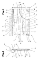
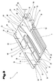
- FIGS. 1 and 2 one is known from the prior art Embodiment of a plate-shaped housing 1 made of metal or plastic shown, which is a rectangular plan with a width 2 and one to the right Angle measured length 3 has.
- the width 2 distances two parallel to each other extending longitudinal side surfaces 4, which are perpendicular to each other by the length 3 spaced transverse side surfaces 5 run.
- the plate-shaped receiving housing 1 has a base plate 6 and a cover plate 7, which are detachably or non-detachably connected to each other are.
- the longitudinal side surfaces 4 and transverse side surfaces 5 also preferably run perpendicular to the base plate 6 and to the cover plate 7.
- Transverse side surfaces 5 extend inside receiving chambers 8, in which objects, arranged in particular commodities 9, but also consumer items are.
- a longitudinal side surface 4 is with a top 10 extending at right angles to this Cover plate 7 connected via an inclined surface 11, which from the longitudinal side surface 4 in Direction of the top 10 and the second longitudinal side surface 4 by an angle of inclination 12 runs inclined.
- the second longitudinal side surface 4 and / or the transverse side faces 5 or at least parts of the longitudinal side faces 4 or transverse side faces 5 are inclined to the base and / or cover plate 6 and 7 and the inclined surface 11 train.
- the inclined surface 11 or a region of the base plate assigned to it 6 and / or the cover plate 7 has a scale 13, in particular a length scale 14 on.
- the receiving chamber 8 extends adjacent to the inclined surface 11 for a knife 15 forming the utility object 9, a knife blade 16 from the base plate 6 and the cover plate 7 in the direction perpendicular to the top 10 is delimited.
- a knife handle 17 is in a connecting surface 18 of the base plate 6 with the cover plate 7 facing away from one of the top 10 and parallel to this extending underside 19 of the base plate 6 projecting recess groove 20 is arranged and thus only bounded in the direction of the bottom 19 by the base plate 6. Consequently the receiving chamber 8 for the commodity 9, i.e. for the knife 15, of the Base plate 6 and at least in some areas from the cover plate running parallel to this 7 bounded.
- the knife handle 17 has a grip surface 21 which is approximately parallel and runs flat with the top 10.
- Receiving chamber 8 arranged for a file 22, for example. This is towards the top 10 and the bottom 19 delimited by the cover plate 7 and the base plate 6, wherein a receiving opening 23 for the file 22, through which this in the receiving chamber 8 can be inserted, is arranged in the transverse side surface 5.
- the cover plate 7 has a rectangular recess 24, which from the transverse side surface 5 in the direction of this protrudes opposite transverse side surface 5 and in which a file handle 25 is arranged is that it is accessible via the recess 24 from the outside. This enables easy Handle the file 22 and thus an easy insertion and removal of the same with respect to the Receiving chamber 8.
- a portion of the receiving chamber 8 is thereby over the recess 24, as is also available for receiving the knife handle 17 and also in the base plate 6 can be arranged made accessible.
- the length 3 must not be less than 70 mm and no greater than 90 mm and forms, as the width 2, a multiple of the thickness 35 of the receiving housing 1, which creates an accommodation in conventional compartments, such as those in wallets, briefcases or schedule folders are provided.
- the thickness 35 of the receiving housing 1 with increasing length 3 less the thickness 35 of the receiving housing 1 according to the ratio of thickness 35 (D) less than or equal to [1/18 times (70 - length 3) + 5] reduced. It is possible that all Receiving openings 23 of the receiving chambers 8 on a transverse side surface 5 or longitudinal side surface 4 are arranged.
- a cross-sectional dimension can at least a part of a receiving chamber 8 with low tolerance to a cross-sectional shape of the Utility item 9 and / or the consumer item, which over it can also be held in the receiving chamber 8 via friction.
- the cover plate 7 from the base plate 6 via one, especially the receiving chambers 8 to keep the central part spaced apart from one another and via a connecting means, in particular to connect an adhesive or weld seam.
- the swivel plate 28 can in the area of a curved end face a protruding locking projection have, which in a locking recess of a commodity 9, such as the Scissors 26, engages and secures them against automatic solution.
- a commodity 9 such as the Scissors 26
- Known receiving housing 1 is formed as a one-piece component, for example as an injection molded part be, the receiving chambers 8 for the commodities 9 and / or Consumables are shaped by means of a slide during the injection molding process.
- the receiving opening is located on the transverse side surface 5 opposite the step 42 23 for the file 22 shown in FIG. 1.
- This also has a gradation 42 and a recess groove 20.
- the recess groove 20 runs at right angles to the transverse side surface 5 and has in one of the transverse side surface 5 in the direction of this opposite Transverse side surface 5 spaced by a partial length 44, a shoulder 45, whereby the groove depth 39 in the area of the transverse side surface 5 is greater than a partial groove depth 46 one from the shoulder 45 in the direction of an end face 47 extending portion 48 of the groove 20.
- Parallel a further deepening groove 20 runs to this deepening groove 20, which is for receiving any other commodity 9 or consumer item.
- the guide surface 53 has an area adjacent to the swivel mount 31 Longitudinal side surface 4 a stop surface 54 running parallel to this, which a parallel has to the transverse side surface 5 extending end surface 55 which from the center 52 around a distance 56 measured parallel to the longitudinal side surface 4 is spaced, which is smaller is as the radius 51.
- the center point 52 is located on a curved center line 57 of the swivel mount 31, which has a curved slide track 32 for the swivel pin 30 - as can be seen in FIG. 1 - and one perpendicular to the base surface 49 in the direction the underside 19 has a measured depth 58 which is less than one of the base area 49 and the underside 19 bounded base height 59.
- the swivel mount 31 is designed in the form of a cylindrical blind bore.
- the recess groove 20 for the scissors 26 shown in FIG. 1 has two facing each other Flank surfaces 60, which do not run parallel to the longitudinal side surfaces 4, but instead the outer shape of the scissors 26 are reproduced.
- the cover plate 7 has a slot-shaped opening running parallel to the longitudinal side surface 4 61, which extends from the transverse side face 5 in the direction of this and parallel extends transverse side surface 5 by an opening depth 62 and the recess 24 formed.
- the slot-shaped opening 61 is through an arcuate end face 63, which is distanced from the transverse side surface 5 by the opening depth 62. From the end face 63 extends opposite to the slot-shaped opening 61 the recess groove 20, which runs parallel to the longitudinal side surface 4.
- the slit-shaped Opening 61 and the recess groove 20 of the cover plate 7 correspond to the recess groove 20 and the connecting surface 18 of the base plate 6 and each form a partial area the receiving chamber 8 for the knife 15 shown in Fig.
- the slot-shaped opening 61 thereby breaks through both the connecting surface 18 as well as the top 10.
- the transverse side surface 5 and Longitudinal side surface 4 are connected in the corner area 29 via a guide profile 64. This is composed of an approximately perpendicular to the connecting surface 18 Guide surface 65, which is in a radius of curvature 66 around the center shown in FIG. 3 52 runs.
- the radius of curvature 66 is larger than that by a distance 67 3 shows the radius 51 of the guide surface 53 of the base plate 6.
- the distance 67 is spaced an end face 68 which runs concentrically to the curved surface 65 and which around an end face radius 69 around the center point 52, which is approximately the radius 51 corresponds to the guide surface 53.
- the guide surface 65 points in the transition area with the Longitudinal side surface 4 has an arcuate depression 70 on which the guide surface 65 protrudes opposite the end face 68.
- a guide arrangement 71 created, which consists of the guide surface 53 of the guide surface 65 and one running approximately parallel to the connecting surface 18, in the form of a circular arc around the center 52 arranged, delimited by the end face 68 and the guide surface 65 Annular surface 72 formed.
- transverse side surface having the slot-shaped opening 61 5 opposite transverse side surface 5 are the recess grooves 20 for that shown in Fig. 1 File 22, tweezers 33, toothpicks 34 and another tool shown.
- the Recess grooves 20 have the recesses 24, which the top 10 partially break through and serve for better gripping of the tools or their handles.
- the pivot plate 28 is for the receiving housing known from the prior art 1 in perspective or a partial area of the same in section shown. From this it can be seen how the pivot plate 28 is guided in the guide arrangement 71 becomes. This is formed by the guide surface 65 and the annular surface 72, which in of the cover plate 7 are arranged, the guide surface 65 being perpendicular to the upper side 10 and the annular surface 72 extends parallel to the top 10. By the distance 67 is a Cover area of the annular surface 72 and an upper surface 73 of the swivel plate 28 is formed, whereby movement of the pivot plate 28 in the direction of the top 10 is prevented becomes.
- FIGS. 7 to 15 are now in the base plate 6 of the Well-known receiving housing 1 arranged recess grooves 20 with corresponding dimensions shown.
- One of the long side surface forming the recess groove 20 4 adjacent knife recess groove 81 has one parallel to the width 2 measured groove width 82, which is 12.83 mm.
- One parallel to the long side surface 4 extending groove side 83 is from a longitudinal side surface 4 by a distance 84 of 37.3 mm spaced.
- the width 2 is preferably 54 mm, the length 3 is preferably 82 mm.
- Another depression groove 20 forms a needle depression groove 89 which extends from the transverse side surface 5 angularly in the direction of this transverse side surface 5 facing away from the Longitudinal side surface 4 runs.
- a center line 90 of the needle groove 89 therefore closes with an auxiliary line running at right angles to the transverse side surface 5, an angle 91 of 3.5 ° on.
- the receiving opening 23 of the needle recess groove lying in the region of the transverse side surface 5 89 is spaced from the long side surface 4 by a distance 92 of 5.17 mm, wherein the needle recess groove 89 has a length 93 of 33 mm. It also owns As can be seen in FIG.
- a further deepening groove 20 forming file deepening groove 96 is provided with a groove side surface 97 from the longitudinal side surface 4 by a distance 98 of 35.5 mm and has a groove width 99 of 7 mm parallel to this measured. She also has one from the transverse side surface 5 in the direction of the transverse side surface 5 facing away from it, groove length 100 of 58.5 mm measured parallel to the longitudinal side surface 4.
- the file recess groove 96 has - as can be seen in FIG.
- a further tool groove 105 is arranged, which of the transverse side surface 5 runs in the direction of the transverse side surface 5 facing away from it and has an arcuate end portion, the center of which is from the transverse side surface 5 is spaced from the transverse side surface 5 by a groove length 106, which 52 mm is.
- a groove side surface 107 of the tool groove 105 is from the longitudinal side surface 4 spaced apart by a distance 108 of 24.5 mm and has a groove width 109 of 2.2 mm on.
- it has one of the connecting surface 18 in the direction of the bottom 19 measured groove depth 110 of 1.1 mm.
- Another scissor groove 111 forming another groove 20 has a groove side surface 112, which runs parallel to the longitudinal side surface 4 and from this by one Distance 113 of 13.5 mm from the long side surface 4 is spaced.
- An end region 114 the scissor recess groove 111 has an arcuate end face 115, whose center point is spaced 116 from the transverse side surface 5 at a distance 116 of 75 mm is.
- a groove side surface 117 which faces away from the groove side surface 112 extends circular arc-shaped end face 115 in the direction of the transverse side face 5 parallel to the groove side face 112 runs up to a distance 118 of 42.59 mm.
- a groove base 123 of the scissor recess groove 111 is as can be seen in FIG. 12 - from the connecting surface 18 in the direction of the underside 19 a groove depth 124 spaced 1.2 mm apart.
- the groove base 125 of the tool recess groove 105 already described is - as in FIG. 11 can be seen - from the connecting surface 18 in the direction of the underside 19 in a groove depth 126 spaced from 1.1 mm.
- a tweezer groove 127 extends from the transverse side surface 5 by a groove length 128 of 47 mm, which is identical to that of the recess groove 20 of the toothpick 34 shown in FIG. 1.
- the groove width 129 is 3.3 mm and that in FIG.
- the groove depth 130 shown in FIG. 13 is 0.6 mm.
- the swivel mount 31 is in the form of a curved one Long hole formed and has a curved center line 131, which in a radius 132 from a center point 133.
- the center point 133 lies around one Distance 134 in the direction of the longitudinal side surface 4 and transverse side surface 5 of 3.5 mm. Of this extends the radius 51, which delimits the guide surface 53 and is 29 mm.
- the pivot mount 31 has a groove width 135 of 2.5 mm and a groove depth 136 of 2.2 mm.
- the cover plate 7 is now from the stand the receiving housing 1 known in the art is shown in detail. It goes like this described - the slot-shaped opening 61 parallel to the longitudinal side surface 4, at right angles to the transverse side surface 5, from this in the direction of that arranged adjacent to it Transverse side surface 5.
- the slot-shaped opening 61 which forms the recess 24, has an arcuate end face 63, the center of which is at a distance 137 from 35 mm is distanced from the transverse side surface 5.
- An end face 138 that extends from the face 63 in the direction of the transverse side surface 5 extending groove 20 which the Knife depression groove 81, in particular for the knife blade 16 shown in FIG.
- the knife recess groove 81 has - as can be seen in FIG. 18 - one of the connecting surface 18 in Direction of the top 10 measured groove depth 140 of 0.6 mm.
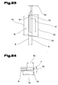
- the knife recess groove also has 81 - as can be seen in FIG. 23 - a measured parallel to the transverse side surface 5 Groove width 141, which is 8.3 mm, the recess 24 being parallel to the groove width 141 measured recess width 142 of 13 mm.
- An opening width is 146 in the area the top 10 about 11.5 mm.
- the knife recess groove 81 runs adjacent File deepening groove 96 into a groove length 147 measured from the transverse side surface 5 of 58.5 mm.
- the file recess groove 96 has the shoulder 45 which - as can be seen in FIG. 19 - Is spaced from the transverse side surface 5 by a length 148 of 20 mm.
- the file recess groove 96 has a groove depth 149 from the connecting surface 18 in Direction of the top 10 of 1.2 mm and a groove depth 150, which is the distance from the paragraph 45 in the direction of the end region of the file recess groove 96 extending groove bottom of the connecting surface 18 distanced in the direction of the upper side 10 is 0.7 mm.
- the top 10 has a bevel 151 in the region of the length 148.
- the recess 24 of the file recess groove 96 protrudes from the transverse side surface 5 by a depth 152 of 4 mm in front.
- Two mutually facing, parallel to the longitudinal side surface 4 extending groove side surfaces 153 are spaced 154 by 7 mm.
- the bevel 151 runs - 24 - at an angle 155 of 8.7 ° from the transverse side surface 5 in the direction inclined to the top 10 and opens into the top 10 in a length 156 of 6.5 mm.
- the tool groove 105 which is also the Has recess 24, which from the transverse side surface 5 by the depth 152 towards the protrudes from this opposite transverse side surface 5.
- the tool groove 105 has a groove width 157, which is measured parallel to the transverse side surface 5, and which is 2.2 mm. Furthermore, it projects from the transverse side surface 5 in the direction of the transverse side surface 5 facing away from it in front, wherein it is semicircular in an end region and a center point in a distance 158 of 52 mm from the transverse side surface 5.
- a groove depth 159 the tool groove 105 is - as can be seen in FIG. 20 - from the connecting surface 18 in Direction of the top 10 1.1 mm. There is also a bevel in this recess groove 20 151 present at the top 10.
- Both the tweezer recess groove 127 and the recess groove 20 for the toothpicks 34 shown in FIG. 1 extend from the transverse side surface 5 into one Length 168 of 47 mm parallel to the long side surface 4.
- the recesses 24 of these two Deepening grooves 20 are analogous to the versions already described, as is the bevel 151.
- a groove depth 169 of these two recess grooves 20 is - as in FIG. 21 visible - 0.6 mm.
- the width 2 of the cover plate 7 is approximately 52.8 mm, the length 3 in about 82 mm.
- the scissor-groove 111 has - as can be seen in Fig. 22 - one Groove depth 170 of 1 mm.
- the swivel plate 28 is now for the from Known prior art receptacle housing 1 shown with detailed measurements.
- the outer ring surface 79 extends in a radius 171 of 29 mm around a center point 172. This is at a distance 173 from mutually perpendicular end faces 174, which is 3.5 mm.
- the inner radius 175 becomes the center 172 measured, which distances the inner ring surface 74.
- the pivot pin 30 is in one Intersection of the distance 173 and a distance 176, which is 8 mm, arranged and lies eccentrically to the center 172.
- a distance between an inner edge 177 of the inner ring surface 74 is from the end face 174 31.05 mm.
- Outer distance 178 which is measured from the face 174, limits the outer ring surface 79 and is 32.77 mm.
- a distance 179 that is parallel from the face 174 is measured to the outer distance 178 and delimits the outermost point of the extension 80, is approximately 33.05 mm.
- the top 73 of the swivel plate 28 has a step 180, which creates an annular surface 181 is formed, which runs at a depth 182 of 0.7 mm.
- a surface 183 the pivot pin 30 is spaced from the top 73 by a height 184 of approximately 3.4 mm.
- the pivot pin 30 has a pin diameter 185 of 2.3 mm.
- the collar 76 projects beyond the inside 75, which runs parallel to the upper side 73, by a height 186 of 1 mm.
- the top 73 is spaced from the inside 75 by a thickness 187 of 1.2 mm.
- the web 77 which is shown in dashed lines, has a web width 188 of 2 mm and protrudes from the outer ring surface 79 towards the end face 174 by one Length 189 of about 5.5 mm in front.
- All Dimensions can of course be changed as desired.
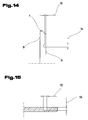
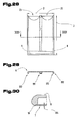
- the side webs 192 each have a shoulder 193 running parallel to the length 3 on which of the top 10, which in this case is predetermined by the base plate 6 is projected in the direction of the bottom 19 by a heel depth 194.
- 193 is
- a cover plate 7 designed as a film is arranged.
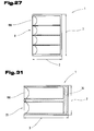
- FIG. 31 A further known embodiment of a receiving housing 1 can be seen in FIG. 31, in which the chewing gum 190 are arranged parallel to the length 3 and in an end area facing away from the receiving openings 23, for example a toothpick 34 is arranged, which runs parallel to the width 2 of the receiving housing 1.
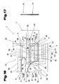
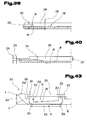
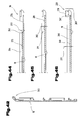
- 35 to 40 is a further embodiment variant of a base plate 6 for an inventive one Shown housing 1 shown.
- the formed by the recess grooves 20 Partial areas of the receiving chambers 8 are at least partially covered by chamber webs 201 circumscribed.
- the recess grooves 20 form a knife recess groove 81, a needle recess groove 89, a file recess groove 96, a tweezer recess groove 127, a scissor recess groove 111, one through the recess groove 20 for the in FIG. 1 as a commodity 9 shown toothpicks 34 formed toothpick recess groove 202 and Ballpoint pen groove 203, which is also formed by a groove 20.
- Chamber webs 201 for the needle recess groove 89 are sectionally formed by partial webs 204 limited, which run at an angle to the transverse side surface 5 towards each other and from are spaced from one another by the groove width 94 measured parallel to the transverse side surface 5. This is smaller than a diameter of a one to be inserted into the needle recess groove 89 Needle 205.
- the knife recess groove 81 in particular that portion of the same which is for receiving of the knife handle 17, has a stop web forming the curved surface 43 206, which allows the knife handle 17 to advance in the direction of the receiving opening 23 prevented for the needle 205.
- Following the stop web 206 preferably extends Clamping web 207 running parallel to the longitudinal side surface 4 in the direction of the insertion opening 23 of the needle 205. As can be seen in FIG. 36, this forms a clamping surface 208, which is inclined to a base surface which preferably runs parallel to the underside 19 209 runs.
- the clamping surface 208 is in the region of the stop web 206 by one Spaced height 210, which is in the direction of the insertion opening 23 of the needle 205th having transverse side surface 5 enlarged.
- a retaining projection 211 is arranged, which the groove bottom 38 opposite to the bottom 19 towers.
- In the area of the receiving opening 23 of the knife recess groove 81 is a parallel to the longitudinal side surface 4 extending centering web 212 is arranged, which from the longitudinal side surface 4 by one at a right angle to this measured exemption width 213 in the corner area Exemption arranged between the longitudinal side surface 4 and the transverse side surface 5 214 is arranged.
- Chamber webs running parallel to one another and to the longitudinal side surface 4 201 for the knife recess groove 81, in particular in the area of the knife handle 17 are spaced from each other by a width measured parallel to the transverse side surface 5, which is larger than the groove width 40.
- the receiving opening 23 of the knife recess groove 81 has adjacent to the scissor recess groove 111 a centering web 215 running at right angles to the transverse side surface 5 Longitudinal side surface 4 has in a corner area between this and the receiving opening 23 also has an exemption 214 for the transverse side face 5 having the needle 205 Centering bar 212 on.
- the stop web 206 has an inclined end face 216 which can be seen in FIG. 38 and which extends at an angle 216 'of approximately 3 ° to 25 ° to the base surface 209.
- the centering bars 212 and 215 have a centering web height 217 measured at right angles to the underside 19 which is less than a web height 218 of the chamber webs designed as longitudinal webs 219 Two hundred and first
- the file recess groove 96 also has a retaining projection 211 and is in the area of the receiving opening 23 delimited by centering webs 220, which run at right angles to the transverse side surface 5.
- a stop web runs at a depth 221 measured at right angles to the transverse side surface 5 222 parallel to the transverse side surface 5 and following this a right angle to the transverse side surface 5 arranged clamping web 223.
- the centering webs 220 have - as in 39 can be seen - a centering web height 224, which is at right angles over the groove bottom 38 raise in the opposite direction to the bottom 19.
- the centering bar height 224 is less than the web height 218 measured parallel to this Longitudinal bars 219.
- the tweezer recess groove 127 runs.
- the receiving opening 23 of the tweezer recess groove 127 is partially parallel to one another and perpendicular to the transverse side surface 5 running centering ridges 220 bounded. These run like those that the file recess groove 96 partially limit, from the transverse side surface 5 to a web length 225, which the centering webs 220 in a direction perpendicular to the transverse side surface 5 limit. Following the web length 225 extend at right angles to the transverse side surface 5 and aligned with the centering webs 220 longitudinal webs 226. These are - as in Fig.
- the receiving opening 23 of the tweezer recess groove 127 is further limited in the direction of the bottom 19 by a cross bar 228, which over the entire groove width 129 of the tweezer recess groove 127 runs and the one crossbar height 229 has which is less than the centering web height 224 or the web height 227. From Transverse web 228 extends, bisecting the groove width 129, parallel to the longitudinal webs 226 running clamping web 230.
- the receiving opening 23 for the Facing away from needle 205 transverse side surface 5 there is the receiving opening 23 for the scissor groove 111.
- this is delimited by a curved web 231 which, in relation to the transverse side surface 5 concave.
- the curvature web forms on a side facing away from the knife recess groove 81 231 the flank surface 60.
- a longitudinal web 232 runs in one Partial area has a formation 233 that of the flank surface 60 of the curved web 231 facing flank surface 60 of the longitudinal web 232 in the direction of the curvature web 231 by a depth 234, which is measured parallel to the transverse side surface 5, projects.
- a stop web 235 In an opposite of the receiving opening 23 of the scissor groove 111 The end region of the same is a stop web 235, which at least partially one Encloses semicircle.
- the transverse side surface 5 which of the other transverse side surface 5 with the partial area is facing away from the receiving opening 23 for the scissor recess groove 111 Part of the receiving opening 23 of the toothpick recess groove 202.
- the partial areas of the receiving opening 23 is in turn made by two perpendicular to the transverse side surface 5 Centering webs 220 and a crossbar running parallel to the transverse side surface 5 228 limited.
- the centering webs 220 are spaced apart from one another by a groove width 236, which is halved by a clamping web 230. This runs from the transverse side surface 5 at right angles to this and is delimited by a clamping web length 237 on which a parallel second transverse web 228 extending to the transverse side surface 5 is arranged.
- longitudinal webs 239 extend which curved symmetrical to each other, so that one of the longitudinal side surface 4 adjacent Area of the receiving opening 23 of the ballpoint pen groove 203 from the long side surface 4 is distanced by a distance 240, which is measured parallel to the transverse side surface 5 and which is less than a distance 241 adjacent to the longitudinal side surface 4 arranged longitudinal web 239 in the end region 242 of the ballpoint pen groove 203. This ensures that when a ballpoint pen is inserted into the ballpoint pen groove 203 this is elastically deformed and automatically in the ballpoint groove 203 is held.
- a connecting web 243 which between the longitudinal web 232 of the scissor recess groove 111 and the adjacently arranged
- the longitudinal web 239 of the ballpoint pen groove 203 runs in the area of the formation 233 is arranged.
- the swivel mount 31 which in this embodiment variant is formed by a pivot bearing bore 244.
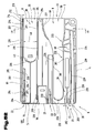
- the cover plate 7 is shown for a receiving housing 1 according to the invention. This is due to the parallel to each other longitudinal side surfaces 4 and limited perpendicular to these and parallel to each other transverse side surfaces 5.
- a centering web 245 runs along a longitudinal side surface 4 and extends in corner regions 246 Centering extensions 247 has.
- the longitudinal side surface 4 has an inclination to the upper side 10 extending inclined surface 11.
- the top 10 facing away and arranged parallel to this runs - as shown in Fig. 43 - an inner side delimiting the centering extensions 247 248, which is spaced from the top 10 by a height 249. This height forms 249 the thickness 35 of the receiving housing 1 shown in FIG. 2, since the centering extensions 247 in the exemptions 214 of the base plate 6 shown in FIG.
- the thickness 35 of the preferably rectangular Receiving housing 1 is between 1.5 mm and 5 mm, preferably 4.0 to 4.3 mm.
- the length 3 must not be less than 70 mm and no greater than 90 mm and forms, as the width 2, a multiple of the thickness 35 of the receiving housing 1, which creates an accommodation in conventional compartments, such as those in wallets, briefcases or schedule folders are provided.
- the thickness 35 of the receiving housing 1 with increasing length 3 less the thickness 35 of the receiving housing 1 according to the ratio of thickness 35 (D) less than or equal to [1/18 times (70 - length 3) + 5] reduced.
- the cover plate 7 has the opening 61 for the recess groove 20 of the knife blade 16, the opening 61 serves in particular to accommodate the knife handle 17.
- the opening 61 as can be seen better in FIG. 43, is delimited by a boundary web 250, which partially extends parallel to the longitudinal side surface 4 and becomes the opening 61 limited in the direction of a transverse side surface 5 by the end face 63.
- the boundary bridge 250 in particular two partial areas running parallel to one another and to the longitudinal side surface 4 of the boundary web 250 forming longitudinal webs 251 face each other Inner sides 252, which consist of vertical surfaces running at right angles to the upper side 10 253 and in the direction of the upper side 10 are formed by curved surfaces 254 in such a way that a measured perpendicular to the longitudinal side surface 4, the vertical surfaces 253 from each other spacing opening width 255 is larger than one in the intersection of the curved surfaces 254 with the top 10 width 256 measured parallel to the opening width 255.
- curvature webs 257 run opposite one another Connect longitudinal webs 258 to the opening 61, of which that of the longitudinal side surface 4 or
- the groove bottom 38 of the knife recess groove arranged in the cover plate 7 81 is inclined to the upper side 10 in some areas.
- the cover plate 7 is located in the opposite direction to the longitudinal side surface 4 arranged file recess groove 96.
- This has a recess 24, which from web-shaped trained centering receptacles 259 is limited.
- Following the web-shaped Centering receptacles 259 extend longitudinal webs 260 parallel to the longitudinal side surface 4 and is at a depth 261 from the recess end face delimiting the recess 24 262, which extends from the transverse side surface 5 in the direction of the second transverse side surface facing away from this 5, in which the opening 61 for the knife 15, in particular for the knife handle 17 is located, is arranged at right angles to the longitudinal webs 260 Crossbar 263 arranged.
- the recess end face 262 is from the transverse side face 5 by an end face depth 265 distanced in the direction of the further transverse side surface 5.
- the next groove 20, which is arranged in the cover plate 7, is the tweezer recess groove 127. This also has the recess 24, which with the recess end face 262 of the transverse side surface 5 is spaced apart by the end face depth 265.
- the tweezer recess groove 127 is also through the web-like centering receptacle 259 circumscribed. Furthermore, it is through a longitudinal web 260 of the file recess groove 96 and through delimits a longitudinal web 266 of the scissor recess groove 111.
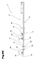
- the web-shaped centering fixtures As can be seen in FIG. 46, 259 have an upper side 267 which is parallel to one another to the top 10 extending base 268 is spaced by a height 269. Furthermore, The centering receptacles 259 extend to a depth 270, in the connection of which, for example the longitudinal webs 260 extend from the base 268 by a web height 271 are distant. The web height 271 is greater than the height 269.
- Recess groove 20 is formed by the scissor depression groove 111, which is also on the cover plate 7 is arranged. This is partly due to the tweezer recess groove 127 delimiting longitudinal web 266, which is in the direction of a quarter circle Recess 272 has a curved course and its continuation in one has circular arc-shaped guide web 273. This forms the guide surface 65 for the pivot plate 28 from.
- the guide surface 65 extends in the radius of curvature 66 from a fictitious center 52. In the area of the top 10, the guide surface 65 a web 274, which is perpendicular to the guide surface 65 in the direction of the center 52 protrudes and a perpendicular to the guide surface 65, facing away from the top 10 Has ring surface 72.
- the longitudinal web 251 of the opening 61 for the knife handle 17 also has a web-shaped Centering receptacle 259.
- the file recess groove 96, in particular the cross bar 263 and the Clamping web 264 have - as can be clearly seen in FIG. 44 - a surface 275 which from a support surface 276 running parallel to the upper side 10 by a height 277 in the opposite Direction to the top 10 is spaced.
- a further recess groove 20 forms the toothpick recess groove arranged on the cover plate 7 202.
- This also has the recess 24, which through the recess end face 262 is limited by an end face depth 265 from the transverse side face 5 distanced in the direction of the approximately quarter-circular recess 272 is.
- the toothpick depression groove 202 is delimited by two grooves running parallel to one another Longitudinal webs 278, which run at right angles to the transverse side surface 5.
- the recess 24 assigned partial areas of the longitudinal webs 278 in turn form web-shaped centering receptacles 259 out.
- Adjacent centering receptacle 259 of the tweezer depression groove 127 runs parallel a centering web 279 to the transverse side surface 5.
- a centering web 279 runs from the the longitudinal side surface 4 adjacent centering 259 of the file recess groove 96 towards the centering extension 247.
- the farthest from the long side surface 4 spaced apart groove 20 forms the ballpoint pen groove arranged in the upper part 7 203, which also has a recess 24.
- the recess 24 is there again limited by web-shaped centering receptacles 259.
- In the corner area between the The transverse side surface 5 and the longitudinal side surface 4 are approximately in the shape of a quarter-circle arc running centering extension 280.
- the toothpick recess groove 202 has, as already executed, the retaining projection 211, which - as shown in Fig. 45 - a parallel to the Top surface 10 extending base surface 281 by a shoulder height 282 in a top surface 10 towers opposite direction.
- FIGS Swivel plate 28 is shown for the receiving housing 1 according to the invention.
- the pivot pin 30 is formed by 90 ° offset pin webs 283, which the Inner side 75 of the swivel plate 28 on the side facing away from an upper side 73 overtop. They protrude from the top 73 by the height 184.
- a stop bar 284 is also formed, which extends from the outer ring surface 79 in the direction protrudes to the pin webs 283.
- the swivel plate 28 has a gradation 180, which is formed by an annular surface 181 running parallel to the upper side 73.
- the Swivel plate 28 also has a swivel stop 285 which passes through the inside 75 opposite to the top 73 projecting stop webs 286 is formed.
- the assembly of the housing 1 according to the invention is as follows carried out.
- the pivot plate 28 is arranged on the base plate 6, in which the the pin webs 283 forming the pivot pin 30 are inserted into the pivot bearing bore 244 become.
- the pin webs 283 are elastically facing each other deformed and caused by locking projections 287 shown in Fig. 48 a fuse against perpendicular to the inside 75, i.e. axially directed movements and thus a backup against automatic release of the swivel plate 28 from the swivel bearing bore 244.
- Die Swivel plate 28 can now along the curvature web 231 by an angular range of in be pivoted about 45 ° until the pivot stop 285 to one in the area of Pivot bearing bore 244 arranged and shown in FIG. 35 delimiting web 288th strikes. Now the pivot plate 28 is pivoted back so that the end faces 174 approximately coincides with a longitudinal side surface 4 or transverse side surface 5, so located the stop bar 284 in an indentation 289 shown in FIG. 35, which in a along the longitudinal side surface 4 extending edge web 290 is arranged.
- connecting webs 294, 301 are assigned.
- This Connecting webs 294, 301 have a considerably smaller width 314 than the thickness 313 of the Webs, e.g. the curvature webs 231 and / or the centering webs 220, the longitudinal webs 219, 226, the stop webs 206 and the chamber webs 201.
- Individual parts of the individual exemplary embodiments can also be used with one another within the scope of the invention can be put together to any combination, so that not only individual Form parts or groups of parts as the subject of your own independent protection can, but that also individual parts, especially the design of the receiving chambers 8 of the individual embodiments are interchangeable, also the Arrangement of the webs or connecting webs 294, 301.
- the plate-shaped housing 1 with additional Holding organs such as projecting holding lugs or the like.
- additional Holding organs such as projecting holding lugs or the like.
- For receiving and holding be provided by credit cards, identification cards or possibly also cash can.
Landscapes
- Purses, Travelling Bags, Baskets, Or Suitcases (AREA)
- Packaging Of Annular Or Rod-Shaped Articles, Wearing Apparel, Cassettes, Or The Like (AREA)
- Packaging For Recording Disks (AREA)
- Accommodation For Nursing Or Treatment Tables (AREA)
- Details Of Measuring And Other Instruments (AREA)
- Sheet Holders (AREA)
- Supports Or Holders For Household Use (AREA)
- Packages (AREA)
- Thermotherapy And Cooling Therapy Devices (AREA)
- Laminated Bodies (AREA)
- Pens And Brushes (AREA)
- Magnetic Record Carriers (AREA)
- Non-Silver Salt Photosensitive Materials And Non-Silver Salt Photography (AREA)
- Catching Or Destruction (AREA)
- Details Of Rigid Or Semi-Rigid Containers (AREA)
Priority Applications (1)
| Application Number | Priority Date | Filing Date | Title |
|---|---|---|---|
| AT02028246T ATE277538T1 (de) | 1995-11-30 | 1996-12-02 | Plattenförmiges aufnahmegehäuse für gebrauchs- und/oder verbrauchsgegenstände |
Applications Claiming Priority (3)
| Application Number | Priority Date | Filing Date | Title |
|---|---|---|---|
| AT196195 | 1995-11-30 | ||
| AT0196195A AT404237B (de) | 1995-11-30 | 1995-11-30 | Plattenförmiges aufnahmegehäuse für gebrauchs- und/oder verbrauchsgegenstände |
| EP96939748A EP0957704B2 (fr) | 1995-11-30 | 1996-12-02 | Etui plat pour objets d'utilisation courante ou de consommation |
Related Parent Applications (1)
| Application Number | Title | Priority Date | Filing Date |
|---|---|---|---|
| EP96939748A Division EP0957704B2 (fr) | 1995-11-30 | 1996-12-02 | Etui plat pour objets d'utilisation courante ou de consommation |
Publications (3)
| Publication Number | Publication Date |
|---|---|
| EP1293144A2 true EP1293144A2 (fr) | 2003-03-19 |
| EP1293144A3 EP1293144A3 (fr) | 2003-03-26 |
| EP1293144B1 EP1293144B1 (fr) | 2004-09-29 |
Family
ID=3524803
Family Applications (2)
| Application Number | Title | Priority Date | Filing Date |
|---|---|---|---|
| EP02028246A Expired - Lifetime EP1293144B1 (fr) | 1995-11-30 | 1996-12-02 | Etui plat pour objets d'utilisation courante ou de consommation |
| EP96939748A Expired - Lifetime EP0957704B2 (fr) | 1995-11-30 | 1996-12-02 | Etui plat pour objets d'utilisation courante ou de consommation |
Family Applications After (1)
| Application Number | Title | Priority Date | Filing Date |
|---|---|---|---|
| EP96939748A Expired - Lifetime EP0957704B2 (fr) | 1995-11-30 | 1996-12-02 | Etui plat pour objets d'utilisation courante ou de consommation |
Country Status (9)
| Country | Link |
|---|---|
| US (4) | US6044967A (fr) |
| EP (2) | EP1293144B1 (fr) |
| JP (1) | JP4098360B2 (fr) |
| CN (1) | CN1161059C (fr) |
| AT (3) | AT404237B (fr) |
| AU (1) | AU7685396A (fr) |
| DE (3) | DE59610769D1 (fr) |
| ES (2) | ES2208767T5 (fr) |
| WO (1) | WO1997019856A2 (fr) |
Families Citing this family (87)
| Publication number | Priority date | Publication date | Assignee | Title |
|---|---|---|---|---|
| CH695370A5 (de) * | 1997-08-08 | 2006-04-28 | Hermann Painsith Dipl Ing | Funktionsteilerträger |
| AT408053B (de) * | 1998-05-18 | 2001-08-27 | Painsith Hermann Dipl Ing | Funktionsteileträger, insbesondere taschenmesser oder plattenförmiges aufnahmegehäuse |
| US7535719B2 (en) * | 1999-08-04 | 2009-05-19 | Super Talent Electronics, Inc. | Single chip USB packages with contact-pins cover |
| US7466556B2 (en) * | 1999-08-04 | 2008-12-16 | Super Talent Electronics, Inc. | Single chip USB packages with swivel cover |
| US7830666B2 (en) | 2000-01-06 | 2010-11-09 | Super Talent Electronics, Inc. | Manufacturing process for single-chip MMC/SD flash memory device with molded asymmetric circuit board |
| US7872871B2 (en) * | 2000-01-06 | 2011-01-18 | Super Talent Electronics, Inc. | Molding methods to manufacture single-chip chip-on-board USB device |
| US8141240B2 (en) | 1999-08-04 | 2012-03-27 | Super Talent Electronics, Inc. | Manufacturing method for micro-SD flash memory card |
| US8102662B2 (en) * | 2007-07-05 | 2012-01-24 | Super Talent Electronics, Inc. | USB package with bistable sliding mechanism |
| US7447037B2 (en) * | 1999-08-04 | 2008-11-04 | Super Talent Electronics, Inc. | Single chip USB packages by various assembly methods |
| US8625270B2 (en) | 1999-08-04 | 2014-01-07 | Super Talent Technology, Corp. | USB flash drive with deploying and retracting functionalities using retractable cover/cap |
| CH694196A5 (de) * | 1999-12-02 | 2004-09-15 | Victorinox Ag | Taschenmesser. |
| AT414328B (de) * | 1999-12-02 | 2007-09-15 | Victorinox Ag | Werkzeugkarte |
| AT410644B8 (de) * | 1999-12-02 | 2003-07-25 | Victorinox Ag | Taschenmesser |
| US7297024B2 (en) * | 2003-09-11 | 2007-11-20 | Super Talent Electronics, Inc. | Universal-serial-bus (USB) flash-memory device with metal wrap formed over plastic housing |
| US20080286990A1 (en) * | 2003-12-02 | 2008-11-20 | Super Talent Electronics, Inc. | Direct Package Mold Process For Single Chip SD Flash Cards |
| US6460698B1 (en) * | 2000-11-27 | 2002-10-08 | Jenn Liang Wang | Planer tool casing |
| US6571940B2 (en) * | 2001-06-01 | 2003-06-03 | Chris M. Newman | Flat article holder |
| AT500390B1 (de) * | 2002-10-30 | 2008-12-15 | Victorinox Ag | Taschenwerkzeug |
| US20050156333A1 (en) * | 2003-09-11 | 2005-07-21 | Super Talent Electronics Inc. | Narrow Universal-Serial-Bus (USB) Flash-Memory Card with Straight Sides using a Ball-Grid-Array (BGA) Chip |
| US7094074B2 (en) * | 2003-09-11 | 2006-08-22 | Super Talent Electronics, Inc. | Manufacturing methods for ultra-slim USB flash-memory card with supporting dividers or underside ribs |
| WO2005043429A2 (fr) * | 2003-10-23 | 2005-05-12 | Kyp (Holdings) Plc | Dispositif destine a etre utilise comme signet ou a des fins promotionnelles |
| US7440286B2 (en) * | 2005-04-21 | 2008-10-21 | Super Talent Electronics, Inc. | Extended USB dual-personality card reader |
| US7872873B2 (en) | 2003-12-02 | 2011-01-18 | Super Talent Electronics, Inc. | Extended COB-USB with dual-personality contacts |
| US8998620B2 (en) * | 2003-12-02 | 2015-04-07 | Super Talent Technology, Corp. | Molding method for COB-EUSB devices and metal housing package |
| US8102657B2 (en) | 2003-12-02 | 2012-01-24 | Super Talent Electronics, Inc. | Single shot molding method for COB USB/EUSB devices with contact pad ribs |
| US9630740B2 (en) * | 2004-04-06 | 2017-04-25 | Wm. Wrigley Jr. Company | Comestible product dispensers and methods of making and using same |
| US7527189B2 (en) * | 2004-04-06 | 2009-05-05 | Wm. Wrigley Jr. Company | Comestible product dispensers and methods of making and using same |
| USD516422S1 (en) | 2004-04-06 | 2006-03-07 | Wm. Wrigley Jr. Company | Dispenser for a comestible product |
| US20070134371A1 (en) * | 2005-12-12 | 2007-06-14 | Jason Billig | Comestible product dispensers and methods of making and using same |
| USD519828S1 (en) | 2004-04-06 | 2006-05-02 | Wm. Wrigley Jr. Company | Comestible product dispenser |
| US8061586B2 (en) * | 2004-04-06 | 2011-11-22 | Wm. Wrigley Jr. Company | Comestible product dispensers and methods of making and using same |
| US20080195817A1 (en) * | 2004-07-08 | 2008-08-14 | Super Talent Electronics, Inc. | SD Flash Memory Card Manufacturing Using Rigid-Flex PCB |
| USD517390S1 (en) * | 2004-08-16 | 2006-03-21 | Tsung-Kai Cheng | Tool card |
| US20060245815A1 (en) * | 2005-05-02 | 2006-11-02 | Chakmakian Gregory A | Wallet card writing instrument |
| US20090308782A1 (en) * | 2007-03-29 | 2009-12-17 | Grist Elizabeth A | Attractive implement kit for personal care usage |
| US8254134B2 (en) | 2007-05-03 | 2012-08-28 | Super Talent Electronics, Inc. | Molded memory card with write protection switch assembly |
| US20090000038A1 (en) * | 2007-05-31 | 2009-01-01 | Padden Stephen J | Plier tool combination |
| US7789680B2 (en) * | 2007-07-05 | 2010-09-07 | Super Talent Electronics, Inc. | USB device with connected cap |
| US8102658B2 (en) * | 2007-07-05 | 2012-01-24 | Super Talent Electronics, Inc. | Micro-SD to secure digital adaptor card and manufacturing method |
| US20090199940A1 (en) * | 2008-02-13 | 2009-08-13 | Toner Machining Technologies, Inc. | Combination Wallet Tool |
| US20090199941A1 (en) * | 2008-02-13 | 2009-08-13 | Toner Machining Technologies, Inc. | Combination Wallet Tool |
| US7984804B2 (en) * | 2008-12-12 | 2011-07-26 | Lebauer Ian F | Portable protective container for electronic devices in conjunction with a multifunction pocket tool |
| USD671814S1 (en) * | 2010-08-05 | 2012-12-04 | Ningbo Power Stationery & Promotion Industry Co., Ltd | Mini toolkit with screwdrivers and flashlight |
| US8967377B2 (en) * | 2012-02-07 | 2015-03-03 | Ian F Lebauer | Protective case for portable electronic device with foldable lens cover and storage compartments |
| USD690931S1 (en) | 2012-04-18 | 2013-10-08 | HUMN Design, LLC | Wallet |
| US9125464B2 (en) | 2012-04-19 | 2015-09-08 | Human Design, Llc | Low profile wallet |
| USD673055S1 (en) | 2012-05-14 | 2012-12-25 | Frank Anthony Cappello | Fluid dispensing apparatus |
| US9092076B2 (en) * | 2013-01-31 | 2015-07-28 | Mastercard International Incorporated | Electronic transaction card with stylus |
| USD745274S1 (en) | 2013-03-13 | 2015-12-15 | HUMN Design, LLC | Wallet |
| USD710179S1 (en) | 2013-09-09 | 2014-08-05 | Fiskars Brands, Inc. | Card tool set |
| US20150240524A1 (en) * | 2014-02-26 | 2015-08-27 | Craig Olroyd | Credit card-sized slim tool set |
| AT515835B1 (de) | 2014-05-28 | 2016-09-15 | Painsith Hermann Dipl Ing | Taschenwerkzeug |
| WO2016046041A1 (fr) * | 2014-09-23 | 2016-03-31 | Victorinox Ag | Coque inférieure destinée à un dispositif de communication et dispositif de communication équipé de ladite coque |
| US10791808B2 (en) | 2015-05-07 | 2020-10-06 | Daniel Kane | Compact wallet |
| CN106308126B (zh) * | 2016-11-19 | 2018-12-28 | 林丽利 | 一种拆卸旋转式多层文件架 |
| US20190166974A1 (en) * | 2017-12-05 | 2019-06-06 | Mark Davidov | Disposable Portable Pocket Fluid/Floss Dispenser |
| USD877594S1 (en) * | 2018-06-08 | 2020-03-10 | Nite Ize, Inc. | Pocket tool |
| US11206910B2 (en) * | 2018-08-01 | 2021-12-28 | Mark Davidov | Disposable portable pocket fluid/floss dispenser |
| USD878891S1 (en) * | 2018-10-11 | 2020-03-24 | Ultimate Survival Tips Llc | Tool card |
| USD881671S1 (en) * | 2018-12-18 | 2020-04-21 | Wen-Chun Kao | Keychain tool |
| US11903466B2 (en) | 2019-01-17 | 2024-02-20 | Dango Products, Llc | Wallet with card holding mechanisms |
| US11571050B2 (en) | 2019-10-22 | 2023-02-07 | Dango Products, Llc | Wallet |
| USD893975S1 (en) * | 2019-01-17 | 2020-08-25 | Dango, Inc. | Separable tool and clip combination |
| US11653729B2 (en) | 2019-10-22 | 2023-05-23 | Dango Products, Llc | Wallet with card holding mechanisms |
| US11178947B2 (en) | 2019-01-17 | 2021-11-23 | Dango Products, Llc | Wallet with card holding mechanisms |
| US11439214B2 (en) | 2019-01-17 | 2022-09-13 | Dango Products, Llc | Wallet |
| USD887708S1 (en) | 2019-02-08 | 2020-06-23 | Thuan Tran | Wallet |
| US11369186B1 (en) * | 2019-07-16 | 2022-06-28 | Full Coverage Security Solutions, LLC | Credit card/identity card holder |
| USD934560S1 (en) | 2020-04-21 | 2021-11-02 | Dango Products, Llc | Wallet |
| USD951632S1 (en) | 2020-10-07 | 2022-05-17 | Dango Products, Llc | Wallet |
| USD972841S1 (en) | 2020-10-12 | 2022-12-20 | Dango Products, Llc | Wallet |
| USD967626S1 (en) | 2020-10-28 | 2022-10-25 | Dango Products, Llc | Wallet |
| KR102284738B1 (ko) * | 2021-03-19 | 2021-08-03 | 윤승수 | 칼 수납 장치 |
| USD950240S1 (en) | 2021-04-09 | 2022-05-03 | Dango Products, Llc | Wallet |
| USD1072474S1 (en) | 2021-07-16 | 2025-04-29 | Ctb Holdings Llc | Wallet |
| USD1031495S1 (en) | 2021-09-03 | 2024-06-18 | Dango Products, Llc | Money clip |
| USD994323S1 (en) | 2021-09-23 | 2023-08-08 | The Ridge Wallet Llc | Key organizer |
| US12484671B2 (en) | 2021-09-29 | 2025-12-02 | Ctb Holdings Llc | Money clip |
| US11425976B1 (en) | 2021-09-29 | 2022-08-30 | Dango Products, Llc | Money clip |
| USD1030312S1 (en) | 2021-10-13 | 2024-06-11 | The Ridge Wallet Llc | Wallet-mounted wireless device holder |
| USD1065827S1 (en) | 2021-10-29 | 2025-03-11 | The Ridge Wallet Llc | Wallet |
| USD1110714S1 (en) | 2021-10-29 | 2026-02-03 | The Ridge Wallet Llc | Wallet |
| USD1098741S1 (en) | 2021-10-29 | 2025-10-21 | The Ridge Wallet Llc | Wallet |
| USD1111431S1 (en) | 2021-10-29 | 2026-02-10 | The Ridge Wallet Llc | Wallet |
| USD1088516S1 (en) | 2022-08-12 | 2025-08-19 | Ctb Holdings Llc | Wallet |
| USD1096144S1 (en) | 2023-01-24 | 2025-10-07 | The Ridge Wallet Llc | Wallet |
| US12119174B1 (en) | 2024-01-26 | 2024-10-15 | The Ridge Wallet Llc | Magnetic plate(s) |
Citations (8)
| Publication number | Priority date | Publication date | Assignee | Title |
|---|---|---|---|---|
| FR613245A (fr) | 1925-08-18 | 1926-11-12 | Nécessaire de couture de poche | |
| FR739682A (fr) | 1932-06-06 | 1933-01-16 | Nécessaire de toilette pour dames | |
| GB2146623A (en) | 1983-09-21 | 1985-04-24 | Ching Huei Lin | Pocket-size container for tools, etc |
| DE3827536C1 (en) | 1988-08-13 | 1989-11-23 | Proline Handels- Und Marketing Gmbh, 8500 Nuernberg, De | Plastic container with key in flat construction |
| DE3834303A1 (de) | 1988-10-08 | 1990-04-12 | Grundig Emv | Aufnahme-wiedergabegeraet, insbesondere telefonanrufbeantworter |
| FR2656779A1 (fr) | 1990-01-09 | 1991-07-12 | Passot Innovation | Boitier pour le stockage des pieces, jetons, cartes, etiquettes.. ou articles similaires pouvant etre associes a un anneau porte-cle. |
| WO1993022948A1 (fr) | 1992-05-13 | 1993-11-25 | Silca S.P.A. | Emsemble clef et boitier combines |
| WO1994029083A2 (fr) | 1993-06-11 | 1994-12-22 | Newman Chris M | Fourreau plat pour ustensiles multiples |
Family Cites Families (42)
| Publication number | Priority date | Publication date | Assignee | Title |
|---|---|---|---|---|
| US2749923A (en) | 1956-06-12 | Toilet article | ||
| FR739628A (fr) | ||||
| GB599405A (en) | 1945-09-18 | 1948-03-11 | Julius Manus Macmicking | Improvements in holders for attachment to or for use as pockets |
| US464405A (en) | 1891-12-01 | Pocket match-safe | ||
| US973930A (en) | 1910-03-05 | 1910-10-25 | John W Fink | Match-box. |
| US1590492A (en) | 1924-05-05 | 1926-06-29 | Benson Anthony Frederick | Pocket case |
| US1731287A (en) | 1928-06-19 | 1929-10-15 | Barnowitz Harry | Combination toilet implement |
| US2080248A (en) | 1935-11-22 | 1937-05-11 | Howard M Ballou | Comb |
| US2122226A (en) | 1937-05-17 | 1938-06-28 | Walter A Wyman | Combination comb and instrument case |
| US2412056A (en) | 1944-09-15 | 1946-12-03 | Mosch Alfred | Utensil holder |
| US2474570A (en) | 1945-03-24 | 1949-06-28 | Emile V Boudreaux | Combination comb and file |
| US2443099A (en) | 1946-03-23 | 1948-06-08 | Roy J Delhaye | Combination comb and carrying case |
| US2491753A (en) | 1946-09-25 | 1949-12-20 | Felmore Company Inc | Comb |
| US2630212A (en) | 1946-10-12 | 1953-03-03 | Mosch Alfred | General utility compact |
| US2511278A (en) | 1949-06-06 | 1950-06-13 | Ronald G Lyle | Combination sheath and nail file |
| US3212546A (en) | 1963-10-14 | 1965-10-19 | Stanley L Lind | Key holder |
| US3461469A (en) | 1966-06-24 | 1969-08-19 | Jessie Morrision | Multipurpose tools and wallet holders therefor |
| US3478683A (en) | 1967-06-05 | 1969-11-18 | Arnold R Hopkins | Safety credit card construction |
| US3563254A (en) | 1969-05-26 | 1971-02-16 | Mary A Gallagher | Combination comb and nail treatment device |
| US3832775A (en) | 1972-08-21 | 1974-09-03 | Salm Inc Arthur | Foldable implement and method of manufacture thereof |
| DE2416752C3 (de) * | 1974-04-05 | 1978-09-07 | Pfeiffer, Michael, 8012 Ottobrunn | Kassette zur Aufnahme von Münzen |
| US4037716A (en) | 1976-06-21 | 1977-07-26 | Marks John D | Card key and/or coin holder |
| US4300610A (en) | 1980-01-31 | 1981-11-17 | Bermas Plastics Company, Inc. | Card-like holder |
| US4331194A (en) | 1980-09-18 | 1982-05-25 | Lederer Richard J | Key holder |
| DE3234778A1 (de) * | 1982-03-24 | 1983-10-06 | Gerhard Ritter | Schutzhuelle fuer eine scheckkarte, automatenkarte, und dergleichen |
| US4562923A (en) * | 1983-03-11 | 1986-01-07 | Pola Chemical Industries Inc. | Cosmetics case |
| US4457425A (en) | 1983-04-21 | 1984-07-03 | Phelon Magnagrip Co., Inc. | Magnetic holder for keys and the like and method of manufacturing the same |
| US4909054A (en) | 1985-07-08 | 1990-03-20 | Fox Robert M | Key shank with rectangular slot and keycase |
| JPH07121631B2 (ja) * | 1987-09-07 | 1995-12-25 | 三菱電機株式会社 | 記憶媒体内蔵カード用プラスチックパッケージ |
| JPH0199226U (fr) * | 1987-12-24 | 1989-07-03 | ||
| US4946030A (en) | 1988-06-20 | 1990-08-07 | Guridi Jose J S | Emergency key holder card |
| SU1706513A1 (ru) | 1988-07-11 | 1992-01-23 | Институт Микробиологии Ан Узсср | Способ получени бактериальной закваски дл лечебно-диетических молочных продуктов |
| DE8813333U1 (de) | 1988-10-22 | 1989-01-12 | Müller, Bernd C. W. | Pflegeset insbesondere für den Reisebedarf |
| NL8802679A (nl) * | 1988-11-02 | 1990-06-01 | Acodeq Trading Co | Inrichting voor het opbergen van kaarten. |
| US4934528A (en) | 1989-02-09 | 1990-06-19 | Mocap | Mirror pouch |
| JPH03113621U (fr) | 1989-10-26 | 1991-11-20 | ||
| US5022247A (en) | 1989-11-24 | 1991-06-11 | Beck J Frederick | Holder for spare set of keys |
| US4979619A (en) * | 1990-01-22 | 1990-12-25 | Hager Alan C | Protective case for collectible sports cards |
| FR2700929B3 (fr) * | 1992-10-30 | 1995-04-14 | Mediana Sa | Porte-cartes pour au moins une carte magnétique. |
| US5328026A (en) * | 1993-06-11 | 1994-07-12 | Newman Chris M | Flat multiple tool holder |
| US5467871A (en) * | 1994-09-06 | 1995-11-21 | Defield; Norman | Key chain note holder with transparent housing |
| US5621936A (en) * | 1994-09-30 | 1997-04-22 | Penaligon; Janet L. | Multi-purpose hand tool |
-
1995
- 1995-11-30 AT AT0196195A patent/AT404237B/de not_active IP Right Cessation
-
1996
- 1996-12-02 WO PCT/AT1996/000238 patent/WO1997019856A2/fr not_active Ceased
- 1996-12-02 DE DE59610769T patent/DE59610769D1/de not_active Expired - Lifetime
- 1996-12-02 JP JP51999297A patent/JP4098360B2/ja not_active Expired - Lifetime
- 1996-12-02 EP EP02028246A patent/EP1293144B1/fr not_active Expired - Lifetime
- 1996-12-02 ES ES96939748T patent/ES2208767T5/es not_active Expired - Lifetime
- 1996-12-02 AT AT02028246T patent/ATE277538T1/de active
- 1996-12-02 ES ES02028246T patent/ES2230442T3/es not_active Expired - Lifetime
- 1996-12-02 EP EP96939748A patent/EP0957704B2/fr not_active Expired - Lifetime
- 1996-12-02 CN CNB961996722A patent/CN1161059C/zh not_active Expired - Lifetime
- 1996-12-02 AT AT96939748T patent/ATE251398T1/de not_active IP Right Cessation
- 1996-12-02 AU AU76853/96A patent/AU7685396A/en not_active Abandoned
- 1996-12-02 DE DE29624203U patent/DE29624203U1/de not_active Expired - Lifetime
- 1996-12-02 US US09/077,482 patent/US6044967A/en not_active Expired - Lifetime
- 1996-12-02 DE DE59611104T patent/DE59611104D1/de not_active Expired - Lifetime
-
1999
- 1999-12-13 US US09/460,268 patent/US6257405B1/en not_active Expired - Lifetime
-
2001
- 2001-06-22 US US09/851,783 patent/US6527112B2/en not_active Expired - Lifetime
-
2002
- 2002-10-07 US US10/265,103 patent/US7631752B2/en not_active Expired - Fee Related
Patent Citations (8)
| Publication number | Priority date | Publication date | Assignee | Title |
|---|---|---|---|---|
| FR613245A (fr) | 1925-08-18 | 1926-11-12 | Nécessaire de couture de poche | |
| FR739682A (fr) | 1932-06-06 | 1933-01-16 | Nécessaire de toilette pour dames | |
| GB2146623A (en) | 1983-09-21 | 1985-04-24 | Ching Huei Lin | Pocket-size container for tools, etc |
| DE3827536C1 (en) | 1988-08-13 | 1989-11-23 | Proline Handels- Und Marketing Gmbh, 8500 Nuernberg, De | Plastic container with key in flat construction |
| DE3834303A1 (de) | 1988-10-08 | 1990-04-12 | Grundig Emv | Aufnahme-wiedergabegeraet, insbesondere telefonanrufbeantworter |
| FR2656779A1 (fr) | 1990-01-09 | 1991-07-12 | Passot Innovation | Boitier pour le stockage des pieces, jetons, cartes, etiquettes.. ou articles similaires pouvant etre associes a un anneau porte-cle. |
| WO1993022948A1 (fr) | 1992-05-13 | 1993-11-25 | Silca S.P.A. | Emsemble clef et boitier combines |
| WO1994029083A2 (fr) | 1993-06-11 | 1994-12-22 | Newman Chris M | Fourreau plat pour ustensiles multiples |
Also Published As
| Publication number | Publication date |
|---|---|
| DE59610769D1 (de) | 2003-11-13 |
| ES2208767T5 (es) | 2007-03-16 |
| WO1997019856A2 (fr) | 1997-06-05 |
| DE29624203U1 (de) | 2001-04-26 |
| US7631752B2 (en) | 2009-12-15 |
| JP4098360B2 (ja) | 2008-06-11 |
| US20030038043A1 (en) | 2003-02-27 |
| EP1293144B1 (fr) | 2004-09-29 |
| ES2208767T3 (es) | 2004-06-16 |
| AT404237B (de) | 1998-09-25 |
| ATE251398T1 (de) | 2003-10-15 |
| HK1017592A1 (en) | 1999-11-26 |
| EP0957704A2 (fr) | 1999-11-24 |
| JP2000501003A (ja) | 2000-02-02 |
| AU7685396A (en) | 1997-06-19 |
| EP0957704B1 (fr) | 2003-10-08 |
| EP0957704B2 (fr) | 2006-07-05 |
| US20010047946A1 (en) | 2001-12-06 |
| CN1161059C (zh) | 2004-08-11 |
| US6257405B1 (en) | 2001-07-10 |
| CN1207653A (zh) | 1999-02-10 |
| US6044967A (en) | 2000-04-04 |
| ES2230442T3 (es) | 2005-05-01 |
| EP1293144A3 (fr) | 2003-03-26 |
| US6527112B2 (en) | 2003-03-04 |
| DE59611104D1 (de) | 2004-11-04 |
| WO1997019856A3 (fr) | 1997-07-31 |
| ATA196195A (de) | 1998-02-15 |
| ATE277538T1 (de) | 2004-10-15 |
Similar Documents
| Publication | Publication Date | Title |
|---|---|---|
| EP1293144B1 (fr) | Etui plat pour objets d'utilisation courante ou de consommation | |
| DE19881229B4 (de) | Funktionsteileträger, insbesondere Taschenmesser | |
| EP1170094B1 (fr) | Outil à main universel du type couteau de poche | |
| DE3707410A1 (de) | Verkaufsregalteiler | |
| DE8717386U1 (de) | Verkaufsregalteiler | |
| AT410644B (de) | Taschenmesser | |
| CH694399A5 (de) | Plattenförmige Werkzeugkarte. | |
| DE2902642A1 (de) | Messer mit zurueckziehbarer klinge | |
| EP0440909B1 (fr) | Ratelier à outils | |
| DE8909551U1 (de) | Dose, insbesondere Pillendose | |
| AT408053B (de) | Funktionsteileträger, insbesondere taschenmesser oder plattenförmiges aufnahmegehäuse | |
| DE19623904C2 (de) | Halter für Wendetafeln od. dgl. | |
| DE19520645A1 (de) | Vorrichtung zum Verpacken von Kraftfahrzeug-Scheiben | |
| EP0160740A2 (fr) | Classeur pour feuilles de papier ou articles analogues | |
| DE2248049C3 (de) | Flachzeichenschiene | |
| AT414328B (de) | Werkzeugkarte | |
| DE8710273U1 (de) | Tastenknopf | |
| DE9001389U1 (de) | Behälter für kleine Gegenstände | |
| AT9250U1 (de) | Linealschutzhülle | |
| DE9211899U1 (de) | Schlüsselkennzeichen | |
| EP1332889A1 (fr) | Corbeille à documents et procédé pour son indexage | |
| DE8907308U1 (de) | Präsentationslade für ringförmige Schmuckstücke | |
| DE29607662U1 (de) | Behälter zur Aufbewahrung und Abgabe von blattförmigen Artikeln | |
| DE9412113U1 (de) | Aufbewahrungs- und Verkaufsbehältnis | |
| WO2009040125A2 (fr) | Boîtier de réception en plaquette, en particulier carte d'outillage |
Legal Events
| Date | Code | Title | Description |
|---|---|---|---|
| PUAI | Public reference made under article 153(3) epc to a published international application that has entered the european phase |
Free format text: ORIGINAL CODE: 0009012 |
|
| PUAL | Search report despatched |
Free format text: ORIGINAL CODE: 0009013 |
|
| 17P | Request for examination filed |
Effective date: 20021216 |
|
| AC | Divisional application: reference to earlier application |
Ref document number: 0957704 Country of ref document: EP Kind code of ref document: P |
|
| AK | Designated contracting states |
Kind code of ref document: A2 Designated state(s): AT CH DE ES FR GB IT LI PT |
|
| AK | Designated contracting states |
Kind code of ref document: A3 Designated state(s): AT CH DE ES FR GB IT LI PT |
|
| GRAP | Despatch of communication of intention to grant a patent |
Free format text: ORIGINAL CODE: EPIDOSNIGR1 |
|
| AKX | Designation fees paid |
Designated state(s): AT CH DE ES FR GB IT LI PT |
|
| GRAS | Grant fee paid |
Free format text: ORIGINAL CODE: EPIDOSNIGR3 |
|
| GRAA | (expected) grant |
Free format text: ORIGINAL CODE: 0009210 |
|
| AC | Divisional application: reference to earlier application |
Ref document number: 0957704 Country of ref document: EP Kind code of ref document: P |
|
| AK | Designated contracting states |
Kind code of ref document: B1 Designated state(s): AT CH DE ES FR GB IT LI PT |
|
| REG | Reference to a national code |
Ref country code: GB Ref legal event code: FG4D Free format text: NOT ENGLISH |
|
| REG | Reference to a national code |
Ref country code: CH Ref legal event code: EP |
|
| REF | Corresponds to: |
Ref document number: 59611104 Country of ref document: DE Date of ref document: 20041104 Kind code of ref document: P |
|
| REG | Reference to a national code |
Ref country code: CH Ref legal event code: NV Representative=s name: ABP PATENT NETWORK SWISS GMBH |
|
| GBT | Gb: translation of ep patent filed (gb section 77(6)(a)/1977) |
Effective date: 20050115 |
|
| REG | Reference to a national code |
Ref country code: ES Ref legal event code: FG2A Ref document number: 2230442 Country of ref document: ES Kind code of ref document: T3 |
|
| PLBE | No opposition filed within time limit |
Free format text: ORIGINAL CODE: 0009261 |
|
| STAA | Information on the status of an ep patent application or granted ep patent |
Free format text: STATUS: NO OPPOSITION FILED WITHIN TIME LIMIT |
|
| ET | Fr: translation filed | ||
| 26N | No opposition filed |
Effective date: 20050630 |
|
| REG | Reference to a national code |
Ref country code: CH Ref legal event code: PFA Owner name: VICTORINOX AG Free format text: VICTORINOX AG#SCHMIEDGASSE 57#6438 IBACH (CH) $ HERMANN PAINSITH#WULFENGASSE 6#9020 KLAGENFURT (AT) -TRANSFER TO- VICTORINOX AG#SCHMIEDGASSE 57#6438 IBACH (CH) $ HERMANN PAINSITH#WULFENGASSE 6#9020 KLAGENFURT (AT) |
|
| PG25 | Lapsed in a contracting state [announced via postgrant information from national office to epo] |
Ref country code: PT Free format text: LAPSE BECAUSE OF NON-PAYMENT OF DUE FEES Effective date: 20050228 |
|
| REG | Reference to a national code |
Ref country code: CH Ref legal event code: NV Representative=s name: ABP PATENT NETWORK AG, CH |
|
| REG | Reference to a national code |
Ref country code: FR Ref legal event code: PLFP Year of fee payment: 20 |
|
| PGFP | Annual fee paid to national office [announced via postgrant information from national office to epo] |
Ref country code: CH Payment date: 20151214 Year of fee payment: 20 Ref country code: GB Payment date: 20151204 Year of fee payment: 20 Ref country code: DE Payment date: 20151203 Year of fee payment: 20 |
|
| PGFP | Annual fee paid to national office [announced via postgrant information from national office to epo] |
Ref country code: FR Payment date: 20151204 Year of fee payment: 20 Ref country code: AT Payment date: 20151207 Year of fee payment: 20 |
|
| PGFP | Annual fee paid to national office [announced via postgrant information from national office to epo] |
Ref country code: ES Payment date: 20151207 Year of fee payment: 20 Ref country code: IT Payment date: 20151223 Year of fee payment: 20 |
|
| REG | Reference to a national code |
Ref country code: CH Ref legal event code: PCAR Free format text: NEW ADDRESS: OTHMARSTRASSE 8, 8008 ZUERICH (CH) |
|
| REG | Reference to a national code |
Ref country code: DE Ref legal event code: R071 Ref document number: 59611104 Country of ref document: DE |
|
| REG | Reference to a national code |
Ref country code: CH Ref legal event code: PL |
|
| REG | Reference to a national code |
Ref country code: GB Ref legal event code: PE20 Expiry date: 20161201 |
|
| REG | Reference to a national code |
Ref country code: AT Ref legal event code: MK07 Ref document number: 277538 Country of ref document: AT Kind code of ref document: T Effective date: 20161202 |
|
| PG25 | Lapsed in a contracting state [announced via postgrant information from national office to epo] |
Ref country code: GB Free format text: LAPSE BECAUSE OF EXPIRATION OF PROTECTION Effective date: 20161201 |
|
| PG25 | Lapsed in a contracting state [announced via postgrant information from national office to epo] |
Ref country code: ES Free format text: LAPSE BECAUSE OF EXPIRATION OF PROTECTION Effective date: 20161203 |