EP1293225B1 - Inhalateur à poudre sèche - Google Patents
Inhalateur à poudre sèche Download PDFInfo
- Publication number
- EP1293225B1 EP1293225B1 EP02020687A EP02020687A EP1293225B1 EP 1293225 B1 EP1293225 B1 EP 1293225B1 EP 02020687 A EP02020687 A EP 02020687A EP 02020687 A EP02020687 A EP 02020687A EP 1293225 B1 EP1293225 B1 EP 1293225B1
- Authority
- EP
- European Patent Office
- Prior art keywords
- rotor
- inhaler
- medicament
- suction air
- driving means
- Prior art date
- Legal status (The legal status is an assumption and is not a legal conclusion. Google has not performed a legal analysis and makes no representation as to the accuracy of the status listed.)
- Expired - Lifetime
Links
- 229940112141 dry powder inhaler Drugs 0.000 title claims description 7
- 239000003814 drug Substances 0.000 claims description 69
- 239000002245 particle Substances 0.000 claims description 34
- 239000002775 capsule Substances 0.000 claims description 8
- 238000011144 upstream manufacturing Methods 0.000 claims description 8
- GUBGYTABKSRVRQ-QKKXKWKRSA-N Lactose Natural products OC[C@H]1O[C@@H](O[C@H]2[C@H](O)[C@@H](O)C(O)O[C@@H]2CO)[C@H](O)[C@@H](O)[C@H]1O GUBGYTABKSRVRQ-QKKXKWKRSA-N 0.000 description 11
- 239000008101 lactose Substances 0.000 description 11
- 230000033001 locomotion Effects 0.000 description 10
- 230000029058 respiratory gaseous exchange Effects 0.000 description 10
- 238000010008 shearing Methods 0.000 description 8
- 210000004072 lung Anatomy 0.000 description 6
- 239000000843 powder Substances 0.000 description 5
- 238000010586 diagram Methods 0.000 description 4
- 229940079593 drug Drugs 0.000 description 3
- 230000001419 dependent effect Effects 0.000 description 2
- 230000004069 differentiation Effects 0.000 description 2
- 239000007788 liquid Substances 0.000 description 2
- 238000000034 method Methods 0.000 description 2
- 238000012986 modification Methods 0.000 description 2
- 230000004048 modification Effects 0.000 description 2
- 230000000149 penetrating effect Effects 0.000 description 2
- 230000002093 peripheral effect Effects 0.000 description 2
- 208000023504 respiratory system disease Diseases 0.000 description 2
- 238000000926 separation method Methods 0.000 description 2
- 230000001225 therapeutic effect Effects 0.000 description 2
- 208000006673 asthma Diseases 0.000 description 1
- 238000001514 detection method Methods 0.000 description 1
- 239000003085 diluting agent Substances 0.000 description 1
- 201000010099 disease Diseases 0.000 description 1
- 208000037265 diseases, disorders, signs and symptoms Diseases 0.000 description 1
- 238000005265 energy consumption Methods 0.000 description 1
- 238000002474 experimental method Methods 0.000 description 1
- 230000002349 favourable effect Effects 0.000 description 1
- 230000005484 gravity Effects 0.000 description 1
- 210000002345 respiratory system Anatomy 0.000 description 1
- 230000001360 synchronised effect Effects 0.000 description 1
- 210000003437 trachea Anatomy 0.000 description 1
Images



Classifications
-
- A—HUMAN NECESSITIES
- A61—MEDICAL OR VETERINARY SCIENCE; HYGIENE
- A61M—DEVICES FOR INTRODUCING MEDIA INTO, OR ONTO, THE BODY; DEVICES FOR TRANSDUCING BODY MEDIA OR FOR TAKING MEDIA FROM THE BODY; DEVICES FOR PRODUCING OR ENDING SLEEP OR STUPOR
- A61M15/00—Inhalators
- A61M15/0028—Inhalators using prepacked dosages, one for each application, e.g. capsules to be perforated or broken-up
-
- A—HUMAN NECESSITIES
- A61—MEDICAL OR VETERINARY SCIENCE; HYGIENE
- A61M—DEVICES FOR INTRODUCING MEDIA INTO, OR ONTO, THE BODY; DEVICES FOR TRANSDUCING BODY MEDIA OR FOR TAKING MEDIA FROM THE BODY; DEVICES FOR PRODUCING OR ENDING SLEEP OR STUPOR
- A61M15/00—Inhalators
- A61M15/0001—Details of inhalators; Constructional features thereof
- A61M15/0005—Details of inhalators; Constructional features thereof with means for agitating the medicament
-
- A—HUMAN NECESSITIES
- A61—MEDICAL OR VETERINARY SCIENCE; HYGIENE
- A61M—DEVICES FOR INTRODUCING MEDIA INTO, OR ONTO, THE BODY; DEVICES FOR TRANSDUCING BODY MEDIA OR FOR TAKING MEDIA FROM THE BODY; DEVICES FOR PRODUCING OR ENDING SLEEP OR STUPOR
- A61M15/00—Inhalators
- A61M15/0028—Inhalators using prepacked dosages, one for each application, e.g. capsules to be perforated or broken-up
- A61M15/003—Inhalators using prepacked dosages, one for each application, e.g. capsules to be perforated or broken-up using capsules, e.g. to be perforated or broken-up
- A61M15/0033—Details of the piercing or cutting means
- A61M15/0035—Piercing means
- A61M15/0036—Piercing means hollow piercing means
-
- A—HUMAN NECESSITIES
- A61—MEDICAL OR VETERINARY SCIENCE; HYGIENE
- A61M—DEVICES FOR INTRODUCING MEDIA INTO, OR ONTO, THE BODY; DEVICES FOR TRANSDUCING BODY MEDIA OR FOR TAKING MEDIA FROM THE BODY; DEVICES FOR PRODUCING OR ENDING SLEEP OR STUPOR
- A61M2202/00—Special media to be introduced, removed or treated
- A61M2202/06—Solids
- A61M2202/064—Powder
-
- A—HUMAN NECESSITIES
- A61—MEDICAL OR VETERINARY SCIENCE; HYGIENE
- A61M—DEVICES FOR INTRODUCING MEDIA INTO, OR ONTO, THE BODY; DEVICES FOR TRANSDUCING BODY MEDIA OR FOR TAKING MEDIA FROM THE BODY; DEVICES FOR PRODUCING OR ENDING SLEEP OR STUPOR
- A61M2205/00—General characteristics of the apparatus
- A61M2205/33—Controlling, regulating or measuring
- A61M2205/3365—Rotational speed
-
- A—HUMAN NECESSITIES
- A61—MEDICAL OR VETERINARY SCIENCE; HYGIENE
- A61M—DEVICES FOR INTRODUCING MEDIA INTO, OR ONTO, THE BODY; DEVICES FOR TRANSDUCING BODY MEDIA OR FOR TAKING MEDIA FROM THE BODY; DEVICES FOR PRODUCING OR ENDING SLEEP OR STUPOR
- A61M2205/00—General characteristics of the apparatus
- A61M2205/82—Internal energy supply devices
- A61M2205/8206—Internal energy supply devices battery-operated
Definitions
- This invention relates to a module of drug particle separator for forming dry powder in an inhaler used by a patient of a respiratory disease for inhaling a medicament, as well as an inhaler provided with such a module.
- Dry powder inhalers for assisting a patient of a respiratory disease such as asthma in inhaling a medicament to control or improve the condition of the disease are becoming commercially available.
- a dry powder medicament is usually formed by attaching 1-10 ⁇ m of effective component (medicament) to several tens to about 100 ⁇ m of lactose as a so-called diluent base for making the dry powder medicament more easily ingestible.
- a dry powder inhaler is adapted to operate by the inhalation of the patient, generating a turbulent flow of air as the patient inhales and causing the medicament to become separated from the lactose such that the patient can inhale the separated medicament.
- medicaments are not always spherical. Some of them may be elongated or needle-shaped. Since the medicament particles generated from a commercially available dry powder inhaler are oriented in various angles, their mass medium aerodynamic diameters are not constant but have a large distribution. As a result, the distribution is also sufficiently large in the position inside the patient's body where the medicaments deposit and this makes the therapeutic effect on the patient difficult to predict.
- Still another problem with the prior art dry powder inhaler is its inability to select a distribution of diameters of particles to be emitted.
- an inhaler which includes a container for holding a liquid inhalant into which a suction cone is submerged for sucking the liquid inhalant from the container and nebulizing the inhalant.
- US-A- 397 1 377 discloses an inhaler showing the features of the preamble of claim 1.
- a dry powder inhaler is as defined in claim 1, characterized not only as comprising a structure providing a flow route for medicament from an upstream side to a downstream side so as to be synchronized with the respiration, a rotor placed in this flow route and a driving means for rotating the rotor, but also wherein the rotor has a convex surface on the upstream side.
- the convex surface of the rotor on the upstream side may include a portion which is conical or semispherical or a portion of a cone or a sphere.
- the rotor surface may be of the shape of a cone with its tip portion removed.
- the medicament particles separated from lactose are floating near the sloped surface of the rotating rotor, they come to be orientated in a same direction if they are of a flat shape or a needle-like shape. Since their aerodynamical particle diameters become uniform, they can be more efficiently deposited at a target position inside the patient.
- the medicament particles are forcibly accelerated towards the rotor and hence can be more effectively separated from lactose.
- a module of the drug particle separator is further provided with a detector for detecting the rotational speed of the rotor and a control unit for controlling the driving means according to the rotational speed of the rotor detected by the detector.
- the drug particle separator can be controlled in various different ways according to the results detected by the detector.
- the rotary speed (the number of rotations per unit time) of the rotor may be adjusted so as to vary the distribution of the diameters of the medicament particles.
- the rotation of the rotor may be controlled according to the measured breathing speed of the patient.
- medicament particles can be generated so as to have a size which is not dependent upon the breathing speed of the patient.
- the rotor may be controlled to start its rotation in synchronism with the breathing of the patient.
- the rotor and the fan are attached to a same rotary shaft, they can be operated by a single driving means, and hence the number of parts to be assembled can be reduced and the module can be made smaller. If the driving means is further arranged coaxially with the rotor and the fan, the series of operations in an airflow including the supply of medicament particles from a source, their separation from lactose and transportation of the separated medicament can be carried out efficiently.
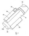
- Fig. 1 is an external view of an inhaler embodying this invention.
- Fig. 2 is its exploded view and
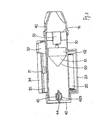
- Fig. 3 is its sectional view.
- the inhaler has a tubular case 10 forming inside a flow route for medicament and includes a battery storage section 12 capable of containing two batteries 20 therein.
- Battery terminals 21 are provided on both sides of the battery storage section 12 and a battery cover 22 is detachably attached thereto.
- a circuit container 14 containing therein a baseboard 30 having mounted thereonto a CPU 31 serving as a control means as well as a switch 32 and being provided with a cover 34.
- the switch 32 is exposed to the exterior, penetrating the cover 34 through a throughhole 34a therethrough.
- a mouthpiece 40 is disengageably engaged to an opening at one end of the case 10 and a bottom cover 42 is engaged to and closes the opposite opening of the tubular case 10.
- a partially open needle 44 is inserted into which is inserted a partially open needle 44, penetrating a capsule 45 containing medicament such that the opening of the needle 44 is situated inside the capsule 45.
- the capsule 45 is supported by being pushed into a supporting frame 42b protruding inward from the bottom cover 42.
- a rotor 50 having a conically shaped surface towards the capsule 45 is rotatably supported inside the case 10.
- the rotor 50 has a conical portion 51 with a sloped outer surface and a circular disk-shaped base portion 52. A small gap is maintained between the outer peripheral surface of the base portion 52 and the inner surface of the case 10.
- the shaft of a rotor motor (or driving means) 55 for causing the rotor 50 to rotate is fastened to the center of the base portion 52 of the rotor 50.
- the motor is affixed to the center of an attachment member 16 formed inside the case 10 such that gaps are provided to the attachment member 16 for allowing air and medicament to flow through.
- the rotary shaft of the motor 55, the central axis of the rotor 50 and the needle 44 are arranged to be in a mutually coaxial relationship inside the case 10.
- the size and shape of the rotor 50 may depend on the size of the inhaler.
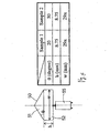
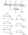
- Fig. 4 shows two examples of rotors with a conically shaped portion 51 in terms of its slope ⁇ with respect to the base portion 52, the height h of the base portion 52 and the outer diameter w of the base portion 52.
- h and w being the same for both Examples 1 and 2.
- the rotor 50 When the switch 32 is pressed to switch on the motor 55, the rotor 50 begins to rotate, If a patient breathes in through the mouthpiece 40, a negative pressure is generated inside the case 10, causing air to flow in through the air hole 42a in the bottom cover 42 and the needle 44 to the interior of the case 10. As the air passes through the needle 44, the medicament inside the capsule 45 is sucked in through the opening of the needle 44 and dispersed inside the case 10. The dispersed medicament is then caused to move towards the rotor 50.
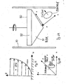
- FIG. 6A shows a coordinate system defined similarly on the surface of the conical portion 51 of the rotor 50 shown in Figs. 1-3, the z-axis being perpendicular to the conical surface, the x- and y-axes being tangent thereto, as shown.
- a suction force results in the x-direction
- a shearing force ⁇ results in the y-direction. Lactose and the medicament are separated by this shearing force.
- the inhaler Since the inhaler is usually used in an upright position with the mouthpiece 40 oriented upward, the separated lactose drops downward by the force of gravity and only the medicament in powder form is sucked in the direction of the mouthpiece 40.
- the medicament can be caused to dependably reach the position of treatment such as a deep interior of the lung and its therapeutic effect can be improved.
- the medicament is floating near the rotating sloped surface of the rotor 50, needle-shaped crystalline particles and flat-shaped particles will come to float at a fixed angle, and the medicament particles come to possess an aerodynamically uniform particle size. This has the favorable result of effectively causing the medicament to be deposited within the patient's body.
- Fig. 7 shows another inhaler according to another embodiment of the invention different from the inhaler described above with reference to Figs. 1-3 only wherein a fan 60 is provided within the case 10 for dispersing and accelerating the medicament towards the rotor 50.
- the fan 60 is attached to a shaft 61 which is in turn attached to the rotor 50 at its center between the capsule 45 and the rotor 50 inside the case 10 so as to be coaxial with the rotor 50 and to rotate together with the rotor 50.
- the fan 60 thus rotating with the rotor 50, serves to forcibly transmit the medicament separated from the capsule 45 towards the sloped surface of the conical portion 51 of the rotor 50.
- the medicament is more effectively separated from lactose. Since the rotor 50, the fan 60 and the motor 55 are arranged coaxially, the space inside the case 10 is efficiently utilized and the separation and emission of medicament can be carried out efficiently in one airflow.
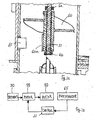
- Figs. 8 and 9 show still another inhaler embodying this invention which is structured similar to the inhaler described above with reference to Fig. 7 but additionally comprises a photosensor 65 for detecting the rotational speed of the rotor 50.
- the photosensor 65 is of a so-called reflected light type, having a target member 60a attached to the tip of the fan 60 to be detected by the photosensor 65.
- the photosensor 65 is disposed on the back side of the base board 30 and a black line is painted on the target member 60a opposite the photosensor 65 such that the rotation of the fan 60 and hence that of the rotor 50 can be thereby detected.
- the photosensor 65 and the target member 60a together form a rotation detector 70 (shown in Fig. 10).
- FIG. 10 A method of operating this inhaler is schematically shown by a block diagram in Fig. 10.
- the rotational speed of the rotor 50 detected by the photosensor 65 is transmitted to the control unit (CPU 31) which serves to carry out a feedback control on the motor 55.
- the rotary motion of the rotor 50 may be controlled in different manners.
- the rotational speed of the rotor 50 may be controlled so as to vary the distribution of particle size of the medicament.
- medicament with particle diameter not dependent upon the patient's breathing speed may be generated.
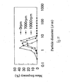
- Fig. 11 is a graph showing the relationship between the rotational speed of the rotor 50 and the particle diameter of medicament and its distribution. As can be seen in Fig.
- the distribution of the medicament particles is centered around about 7 ⁇ m but the distribution comes to center around about 5 ⁇ m if the rotor 50 rotates at the rate of 7000rpm and around about 2 ⁇ m if the rotor 50 rotates at the rate of 10000rpm.
- Recent experiments by the inventors herein show that the distribution is centered around about 1 ⁇ m if the rotor rotates at the rate of 12000rpm.
- the medicament particles may be made uniform to a mass medium aerodynamic diameter of about 1 ⁇ m such that they can efficiently reach a deep part of the patient's body, although it is not desirable to reduce the mass medium aerodynamic diameter to less than 1 ⁇ m because such medicament particles may reach a deep therapy-requiring part of the patient's body but may not be deposited there successfully and may be-breathed out of the body.
- a desired distribution of particle size can be generated by controlling the rotational speed of the rotor 50 independent of the breathing speed of the patient.
- Figs. 12 and 13 show an inhaler according to still another embodiment of the invention, which is similar to the one described above with reference to Figs. 8 and 9 but is characterized wherein its fan 60 and the rotor (and hence its drive shaft 51) are adapted to rotate independently of each other.
- the fan 60 undergoes a rotary motion according to the amount of respiration.
- a target member 60a for detection is attached to the fan 60, and the rotary motion of the fan 60, representing the air suction speed, can be detected by a photosensor 65 (say, of a so-called reflected light type) serving as a suction air speed sensor
- the air suction speed determined by the photosensor 65 is transmitted to a control unit (with a CPU 31) and compared with a preliminarily stored specified speed. If the detected air suction speed is found to exceed this specified speed, the control unit 31 judges that the patient's respiration is sufficiently strong and activates the motor 55 for the rotor 50, causing the rotor 50 to rotate at a specified speed such as 10000rpm.
- numerals 62 indicate stoppers for limiting the movement of the fan 60 along the drive shaft 51 of the motor 50 and numeral 51 indicates a bearing inserted between the shaft for the fan 60 and the drive shaft 51 of the motor 50 for allowing their mutually independent rotary motions.
- the control unit may be programmed so as to control the rotary motion (speed) of the rotor 50 according to the air suction speed by the patient.
- the rate of suction by the patient is determined to be greater than a specified rate, the measured suction rate may be divided into several steps.
- the smaller the mass medium aerodynamic diameter of a medicament the deeper it becomes likely for it to be able to reach in the patient's body.
- medicament particles have a mass, they acquire an inertial force, or momentum, as they begin to move. Larger medicament particles have a larger momentum and cannot change the direction of motion easily. They tend to collide with the inner wall of the trachea and it becomes difficult for them to reach a deeper part of the lung.
- the rotary speed of the rotor 50 need not be changed in a step-wise fashion. It may be changed continuously or linearly corresponding to the air suction speed by the patient.
- the rotation of the rotor 50 may be stopped as the patient stops inhaling and starts to exhale.
- the control unit or the CPU 31
- the control unit may be provided with a timer and control the rotor 50 to continue rotating for a specified length of time (such as a few seconds) once it is detected that a specified amount of air has been breathed in.
- the energy consumption of the batteries can be reduced by any of these control methods because the rotation of the rotor 50 is not started until the patient begins to breath in at a specified air suction rate.
- Rotation of the rotor 50 may also be controlled so as to start in synchronism with the breathing of the patient.
- Fig. 14 shows some of the examples, including conical shapes with a tip portion removed (such as shown in Figs. 14-3 and 14-4) or without a tip portion removed (such as shown in Figs. 14-1 and 14-2) and spherical shapes (such as shown in Figs. 14-5 and 14-6), all with a cylindrical base (such as shown in Figs. 14-1, 14-3 and 14-5) or without a cylindrical base (such as shown in Figs. 14-2, 14-4 and 14-6). All such modifications and variations that may be apparent to a person skilled in the art are intended to be within the scope of this invention.
Landscapes
- Health & Medical Sciences (AREA)
- Engineering & Computer Science (AREA)
- Bioinformatics & Cheminformatics (AREA)
- Pulmonology (AREA)
- Anesthesiology (AREA)
- Biomedical Technology (AREA)
- Heart & Thoracic Surgery (AREA)
- Hematology (AREA)
- Life Sciences & Earth Sciences (AREA)
- Animal Behavior & Ethology (AREA)
- General Health & Medical Sciences (AREA)
- Public Health (AREA)
- Veterinary Medicine (AREA)
- Medicinal Preparation (AREA)
Claims (18)
- Inhalateur à poudre sèche dans lequel un flux d'air est créé par l'intermédiaire d'une action d'inhalation d'un patient pour permettre au patient d'inhaler un médicament, ledit inhalateur comprenant un boîtier (10) définissant un trajet d'écoulement tubulaire pour un médicament depuis un côté en amont vers un côté en aval dudit boîtier (10), une source de médicament (45) disposée sur ledit côté en amont et un embout (40) disposé sur le côté en aval,
un séparateur de particules placé dans ledit trajet d'écoulement d'air à distance de ladite source de médicament (45), ledit séparateur de particules comprenant un rotor (50) entraîné par un moyen d'entraînement (55), caractérisé en ce que ledit rotor a une surface convexe (51) faisant face à ladite source de médicament (45). - Inhalateur selon la revendication 1, dans lequel ladite surface convexe est choisie dans le groupe constitué de surfaces qui sont au moins en partie coniques (51) et des parties d'une surface sphérique.
- Inhalateur selon la revendication 1, comprenant en outre un ventilateur (60) disposé sur ledit côté en amont dudit rotor (50) pour disperser et accélérer ledit médicament vers ledit rotor.
- Inhalateur selon la revendication 1, comprenant en outre un détecteur servant à détecter la vitesse de rotation dudit rotor (50) et une unité de commande pour commander ledit moyen d'entraînement (55) selon la vitesse de rotation dudit rotor détectée par le détecteur.
- Inhalateur selon la revendication 3, comprenant en outre un détecteur servant à détecter la vitesse de rotation dudit rotor (50) et une unité de commande pour commander ledit moyen d'entraînement (55) selon la vitesse de rotation dudit rotor détectée par le détecteur.
- Inhalateur selon la revendication 3, dans lequel ledit ventilateur (60) et ledit rotor (50) sont disposés coaxialement.
- Inhalateur selon la revendication 4, dans lequel ledit ventilateur (60) et ledit rotor (50) sont disposés coaxialement.
- Inhalateur selon la revendication 5, dans lequel ledit ventilateur (60) et ledit rotor (50) sont disposés coaxialement.
- Inhalateur selon la revendication 3, dans lequel ledit ventilateur (60), ledit rotor (50) et ledit moyen d'entraînement (55) sont disposés coaxialement.
- Inhalateur selon la revendication 4, dans lequel ledit ventilateur (60), ledit rotor (50) et ledit moyen d'entraînement (55) sont disposés coaxialement.
- Inhalateur selon la revendication 5, dans lequel ledit ventilateur (60), ledit rotor (50) et ledit moyen d'entraînement (55) sont disposés coaxialement.
- Inhalateur selon la revendication 1, comprenant en outre un couvercle (42) doté d'un évent (42a) disposé en amont dudit rotor (50) et une capsule (45) au niveau dudit évent pour contenir ledit médicament.
- Inhalateur selon la revendication 12, comprenant en outre une aiguille partiellement ouverte (44) insérée dans ledit évent.
- Inhalateur selon la revendication 13, dans lequel un arbre d'entraînement dudit moyen d'entraînement (55), un axe central dudit rotor (50) et ladite aiguille (44) sont disposés coaxialement.
- Inhalateur selon la revendication 1, comprenant en outre un détecteur de vitesse d'aspiration de l'air (65) pour mesurer la vitesse d'aspiration de l'air par un patient, ledit moyen d'entraînement (55) faisant tourner le rotor (50) selon la vitesse d'aspiration de l'air mesurée par ledit détecteur de vitesse d'aspiration de l'air (65).
- Inhalateur selon la revendication 4, comprenant en outre un détecteur de vitesse d'aspiration de l'air (65) pour mesurer la vitesse d'aspiration de l'air par un patient ; ladite unité de commande commandant ledit moyen d'entraînement (55) selon la vitesse d'aspiration de l'air mesurée par ledit détecteur de vitesse d'aspiration de l'air (65).
- Inhalateur selon la revendication 5, comprenant en outre un détecteur de vitesse d'aspiration de l'air (65) pour mesurer la vitesse d'aspiration de l'air par un patient ; ladite unité de commande commandant ledit moyen d'entraînement (55) selon la vitesse d'aspiration de l'air mesurée par ledit détecteur de vitesse d'aspiration de l'air (65).
- Inhalateur selon la revendication 1, dans lequel ledit rotor a une vitesse de rotation supérieure ou égale à 1000 min-1.
Applications Claiming Priority (2)
| Application Number | Priority Date | Filing Date | Title |
|---|---|---|---|
| JP2001278974A JP3619176B2 (ja) | 2001-09-14 | 2001-09-14 | エアロゾル粒子分別装置及び吸入器 |
| JP2001278974 | 2001-09-14 |
Publications (3)
| Publication Number | Publication Date |
|---|---|
| EP1293225A2 EP1293225A2 (fr) | 2003-03-19 |
| EP1293225A3 EP1293225A3 (fr) | 2003-08-20 |
| EP1293225B1 true EP1293225B1 (fr) | 2007-08-08 |
Family
ID=19103249
Family Applications (1)
| Application Number | Title | Priority Date | Filing Date |
|---|---|---|---|
| EP02020687A Expired - Lifetime EP1293225B1 (fr) | 2001-09-14 | 2002-09-13 | Inhalateur à poudre sèche |
Country Status (4)
| Country | Link |
|---|---|
| US (1) | US20030056789A1 (fr) |
| EP (1) | EP1293225B1 (fr) |
| JP (1) | JP3619176B2 (fr) |
| DE (1) | DE60221611T2 (fr) |
Families Citing this family (20)
| Publication number | Priority date | Publication date | Assignee | Title |
|---|---|---|---|---|
| GB9924808D0 (en) * | 1999-10-21 | 1999-12-22 | Glaxo Group Ltd | Medicament dispenser |
| GB9924780D0 (en) | 1999-10-21 | 1999-12-22 | Glaxo Group Ltd | Medicament dispenser |
| FR2856930B1 (fr) * | 2003-07-04 | 2007-09-07 | Saime Sarl | Dispositif d'aide a la respiration a turbine et capteur modulaires. |
| ATE538763T1 (de) | 2004-01-22 | 2012-01-15 | Thermocure | Atemsystem zur einleitung von therapeutischer hypothermie |
| US7168101B2 (en) * | 2005-02-14 | 2007-01-30 | Tesfa Guma | Security underwear device for sexual organs |
| US7987845B2 (en) * | 2006-01-31 | 2011-08-02 | Oriel Therapeutics, Inc. | Dry powder inhalers having spiral travel paths, unit dose microcartridges with dry powder, related devices and methods |
| JP5713406B2 (ja) * | 2008-12-02 | 2015-05-07 | クール セラピューティクス, インコーポレイテッド | 微細氷粒子を有する呼吸ガスの送達のためのシステム |
| EP3834869B1 (fr) | 2010-12-22 | 2024-06-05 | Syqe Medical Ltd. | Système d'administration de médicament |
| JP2013132473A (ja) * | 2011-12-27 | 2013-07-08 | Omron Healthcare Co Ltd | ネブライザおよびネブライザキット |
| US10238831B2 (en) | 2013-09-08 | 2019-03-26 | Qool Therapeutics, Inc. | Temperature measurement and feedback for therapeutic hypothermia |
| US11298477B2 (en) | 2014-06-30 | 2022-04-12 | Syqe Medical Ltd. | Methods, devices and systems for pulmonary delivery of active agents |
| RU2721064C2 (ru) | 2014-06-30 | 2020-05-15 | Сике Медикал Лтд. | Ингалятор с регулированием потока |
| RU2723335C2 (ru) | 2014-06-30 | 2020-06-09 | Сике Медикал Лтд. | Дозовый картридж для ингалятора |
| CA3219298A1 (fr) * | 2014-06-30 | 2016-01-07 | Syqe Medical Ltd. | Cartouche de dose de medicament pour un dispositif d'inhalateur |
| AU2015283589B2 (en) | 2014-06-30 | 2019-09-12 | Syqe Medical Ltd. | Method and device for vaporization and inhalation of isolated substances |
| EP3261593B1 (fr) | 2015-02-23 | 2021-11-03 | Qool Therapeutics, Inc. | Systèmes et procédés pour l'administration endotrachéale de particules congelées |
| CA3009599A1 (fr) | 2016-01-06 | 2017-07-13 | Syqe Medical Ltd. | Traitement therapeutique a faible dose |
| US11559081B2 (en) | 2016-10-11 | 2023-01-24 | Nicoventures Trading Limited | Aerosol provision system having a base for supporting one or more receptacles |
| US20220184326A1 (en) * | 2019-03-11 | 2022-06-16 | Health Research, Inc. | Medicinal nebulizer and method of dispensing medicament |
| CN119405953B (zh) * | 2024-12-10 | 2025-09-30 | 中国人民解放军陆军军医大学第一附属医院 | 吸入型药物的给药装置 |
Family Cites Families (12)
| Publication number | Priority date | Publication date | Assignee | Title |
|---|---|---|---|---|
| US3831606A (en) * | 1971-02-19 | 1974-08-27 | Alza Corp | Auto inhaler |
| GB1459426A (en) * | 1973-02-26 | 1976-12-22 | Allen & Hanburys Ltd | Inhalation devices |
| US3971377A (en) * | 1974-06-10 | 1976-07-27 | Alza Corporation | Medicament dispensing process for inhalation therapy |
| IT1116047B (it) * | 1979-04-27 | 1986-02-10 | Sigma Tau Ind Farmaceuti | Dispositivo per la rapida inalazione di farmaci in polvere da parte di persone sofferenti di asma |
| DE3274065D1 (de) * | 1981-07-08 | 1986-12-11 | Draco Ab | Powder inhalator |
| DE3419148C1 (de) * | 1984-05-23 | 1985-08-01 | Hans Ulrich 7912 Weißenhorn Klimt | Inhalationsgeraet |
| US4739754A (en) * | 1986-05-06 | 1988-04-26 | Shaner William T | Suction resistant inhalator |
| SK51695A3 (en) * | 1992-10-19 | 1995-11-08 | Dura Pharma Inc | Dry powder medicament inhaler |
| DE69413989T2 (de) * | 1993-08-18 | 1999-04-08 | Fisons Plc, Ipswich, Suffolk | Inhalator mit atemstromregelung |
| US6102036A (en) * | 1994-04-12 | 2000-08-15 | Smoke-Stop | Breath activated inhaler |
| SE9700937D0 (sv) * | 1997-03-14 | 1997-03-14 | Astra Ab | Powder inhaler I |
| US6237591B1 (en) * | 1998-11-02 | 2001-05-29 | Dura Pharmaceuticals, Inc. | Turbine dry powder inhaler |
-
2001
- 2001-09-14 JP JP2001278974A patent/JP3619176B2/ja not_active Expired - Fee Related
-
2002
- 2002-09-10 US US10/241,977 patent/US20030056789A1/en not_active Abandoned
- 2002-09-13 EP EP02020687A patent/EP1293225B1/fr not_active Expired - Lifetime
- 2002-09-13 DE DE60221611T patent/DE60221611T2/de not_active Expired - Lifetime
Also Published As
| Publication number | Publication date |
|---|---|
| EP1293225A2 (fr) | 2003-03-19 |
| EP1293225A3 (fr) | 2003-08-20 |
| US20030056789A1 (en) | 2003-03-27 |
| DE60221611D1 (de) | 2007-09-20 |
| DE60221611T2 (de) | 2008-05-21 |
| JP3619176B2 (ja) | 2005-02-09 |
| JP2003079731A (ja) | 2003-03-18 |
Similar Documents
| Publication | Publication Date | Title |
|---|---|---|
| EP1293225B1 (fr) | Inhalateur à poudre sèche | |
| US20220126036A1 (en) | Systems and methods of aerosol delivery with airflow regulation | |
| AU2009212849B2 (en) | Unit dose cartridge and dry powder inhaler | |
| US5823434A (en) | Electromechanical driver for an aerosol dispensing apparatus which dispenses a medicated vapor into the lungs of a patient | |
| EP2183010B1 (fr) | Appareil d'administration de médicament | |
| US6948496B2 (en) | Inhalers | |
| AU659727B2 (en) | Powder nebulizer apparatus and method of nebulization | |
| US20090056708A1 (en) | Device, system and method for targeting aerosolized particles to a specific area of the lungs | |
| CN110799231A (zh) | 干粉输送装置及其使用方法 | |
| US20080223364A1 (en) | Dry powder aerosol generator | |
| CN222968974U (zh) | 一种粉雾剂吸入器的吸嘴组件及粉雾剂吸入器 | |
| HK1094325A (en) | Unit dose cartridge and dry powder inhaler | |
| HK1094325B (en) | Unit dose cartridge and dry powder inhaler |
Legal Events
| Date | Code | Title | Description |
|---|---|---|---|
| PUAI | Public reference made under article 153(3) epc to a published international application that has entered the european phase |
Free format text: ORIGINAL CODE: 0009012 |
|
| AK | Designated contracting states |
Kind code of ref document: A2 Designated state(s): AT BE BG CH CY CZ DE DK EE ES FI FR GB GR IE IT LI LU MC NL PT SE SK TR |
|
| AX | Request for extension of the european patent |
Extension state: AL LT LV MK RO SI |
|
| RIN1 | Information on inventor provided before grant (corrected) |
Inventor name: ASAI, KEI,C/O OMRON CORP.,801, MINAMIFUDODO-CHO Inventor name: TAKANO, HIROSHI,C/O DOSHISHA UNIVERSITY Inventor name: TABATA, MAKOTO,OMRON CORP.,801, MINAMIFUDODO-CHO |
|
| PUAL | Search report despatched |
Free format text: ORIGINAL CODE: 0009013 |
|
| AK | Designated contracting states |
Designated state(s): AT BE BG CH CY CZ DE DK EE ES FI FR GB GR IE IT LI LU MC NL PT SE SK TR |
|
| AX | Request for extension of the european patent |
Extension state: AL LT LV MK RO SI |
|
| RAP1 | Party data changed (applicant data changed or rights of an application transferred) |
Owner name: TAKANO, HIROSHI Owner name: OMRON HEALTHCARE CO., LTD. |
|
| 17P | Request for examination filed |
Effective date: 20040128 |
|
| AKX | Designation fees paid |
Designated state(s): DE GB SE |
|
| RAP1 | Party data changed (applicant data changed or rights of an application transferred) |
Owner name: TAKANO, HIROSHI Owner name: OMRON HEALTHCARE CO., LTD. |
|
| GRAP | Despatch of communication of intention to grant a patent |
Free format text: ORIGINAL CODE: EPIDOSNIGR1 |
|
| GRAS | Grant fee paid |
Free format text: ORIGINAL CODE: EPIDOSNIGR3 |
|
| GRAA | (expected) grant |
Free format text: ORIGINAL CODE: 0009210 |
|
| RIN1 | Information on inventor provided before grant (corrected) |
Inventor name: ASAI, KEI,C Inventor name: TAKANO, HIROSHI,C/O DOSHISHA UNIVERSITY Inventor name: TABATA, MAKOTO,C/O OMRON HEALTHCARE CO. LTD. |
|
| AK | Designated contracting states |
Kind code of ref document: B1 Designated state(s): DE GB SE |
|
| REG | Reference to a national code |
Ref country code: GB Ref legal event code: FG4D |
|
| REF | Corresponds to: |
Ref document number: 60221611 Country of ref document: DE Date of ref document: 20070920 Kind code of ref document: P |
|
| RIN2 | Information on inventor provided after grant (corrected) |
Inventor name: TAKANO, HIROSHI,C/O DOSHISHA UNIVERSITY Inventor name: ASAI, KEI,C/O OMRON HEALTHCARE CO. LTD. Inventor name: TABATA, MAKOTO C/O OMRON HEALTHCARE CO. LTD. |
|
| REG | Reference to a national code |
Ref country code: SE Ref legal event code: TRGR |
|
| PLBE | No opposition filed within time limit |
Free format text: ORIGINAL CODE: 0009261 |
|
| STAA | Information on the status of an ep patent application or granted ep patent |
Free format text: STATUS: NO OPPOSITION FILED WITHIN TIME LIMIT |
|
| 26N | No opposition filed |
Effective date: 20080509 |
|
| REG | Reference to a national code |
Ref country code: DE Ref legal event code: R082 Ref document number: 60221611 Country of ref document: DE Representative=s name: KILIAN KILIAN & PARTNER, DE |
|
| PGFP | Annual fee paid to national office [announced via postgrant information from national office to epo] |
Ref country code: DE Payment date: 20130930 Year of fee payment: 12 Ref country code: SE Payment date: 20130924 Year of fee payment: 12 |
|
| PGFP | Annual fee paid to national office [announced via postgrant information from national office to epo] |
Ref country code: GB Payment date: 20130920 Year of fee payment: 12 |
|
| REG | Reference to a national code |
Ref country code: DE Ref legal event code: R119 Ref document number: 60221611 Country of ref document: DE |
|
| REG | Reference to a national code |
Ref country code: SE Ref legal event code: EUG |
|
| GBPC | Gb: european patent ceased through non-payment of renewal fee |
Effective date: 20140913 |
|
| PG25 | Lapsed in a contracting state [announced via postgrant information from national office to epo] |
Ref country code: SE Free format text: LAPSE BECAUSE OF NON-PAYMENT OF DUE FEES Effective date: 20140914 |
|
| PG25 | Lapsed in a contracting state [announced via postgrant information from national office to epo] |
Ref country code: DE Free format text: LAPSE BECAUSE OF NON-PAYMENT OF DUE FEES Effective date: 20150401 Ref country code: GB Free format text: LAPSE BECAUSE OF NON-PAYMENT OF DUE FEES Effective date: 20140913 |