EP1293394B1 - Producteur de gaz pour coussin de securite gonflable - Google Patents
Producteur de gaz pour coussin de securite gonflable Download PDFInfo
- Publication number
- EP1293394B1 EP1293394B1 EP01941160A EP01941160A EP1293394B1 EP 1293394 B1 EP1293394 B1 EP 1293394B1 EP 01941160 A EP01941160 A EP 01941160A EP 01941160 A EP01941160 A EP 01941160A EP 1293394 B1 EP1293394 B1 EP 1293394B1
- Authority
- EP
- European Patent Office
- Prior art keywords
- igniter
- air bag
- gas generator
- pin
- gas
- Prior art date
- Legal status (The legal status is an assumption and is not a legal conclusion. Google has not performed a legal analysis and makes no representation as to the accuracy of the status listed.)
- Expired - Lifetime
Links
- 239000007789 gas Substances 0.000 claims description 110
- 239000003999 initiator Substances 0.000 claims description 48
- 230000037452 priming Effects 0.000 claims description 37
- 238000002485 combustion reaction Methods 0.000 claims description 21
- 238000003825 pressing Methods 0.000 claims description 19
- 230000004913 activation Effects 0.000 claims description 18
- 229910052751 metal Inorganic materials 0.000 claims description 18
- 239000002184 metal Substances 0.000 claims description 18
- 239000011810 insulating material Substances 0.000 claims description 16
- 239000000567 combustion gas Substances 0.000 claims description 8
- 238000000034 method Methods 0.000 claims description 8
- 238000007599 discharging Methods 0.000 claims description 6
- 230000007257 malfunction Effects 0.000 abstract 1
- 229920005989 resin Polymers 0.000 description 26
- 239000011347 resin Substances 0.000 description 26
- 239000003795 chemical substances by application Substances 0.000 description 13
- 239000000463 material Substances 0.000 description 10
- 239000004033 plastic Substances 0.000 description 10
- 229920003023 plastic Polymers 0.000 description 10
- 238000005192 partition Methods 0.000 description 8
- 230000001133 acceleration Effects 0.000 description 7
- 239000011521 glass Substances 0.000 description 7
- 238000000465 moulding Methods 0.000 description 7
- 239000004065 semiconductor Substances 0.000 description 7
- 239000010408 film Substances 0.000 description 6
- 230000003213 activating effect Effects 0.000 description 4
- 238000002788 crimping Methods 0.000 description 3
- 238000010292 electrical insulation Methods 0.000 description 3
- 238000001746 injection moulding Methods 0.000 description 3
- 238000009413 insulation Methods 0.000 description 3
- 230000002093 peripheral effect Effects 0.000 description 3
- 239000010409 thin film Substances 0.000 description 3
- 229910052782 aluminium Inorganic materials 0.000 description 2
- XAGFODPZIPBFFR-UHFFFAOYSA-N aluminium Chemical compound [Al] XAGFODPZIPBFFR-UHFFFAOYSA-N 0.000 description 2
- 239000002826 coolant Substances 0.000 description 2
- 230000000694 effects Effects 0.000 description 2
- 238000005304 joining Methods 0.000 description 2
- 238000004519 manufacturing process Methods 0.000 description 2
- 229920001707 polybutylene terephthalate Polymers 0.000 description 2
- 230000000717 retained effect Effects 0.000 description 2
- 238000007665 sagging Methods 0.000 description 2
- 239000004677 Nylon Substances 0.000 description 1
- 229920002292 Nylon 6 Polymers 0.000 description 1
- 229920002302 Nylon 6,6 Polymers 0.000 description 1
- 229920000572 Nylon 6/12 Polymers 0.000 description 1
- 229930182556 Polyacetal Natural products 0.000 description 1
- XUIMIQQOPSSXEZ-UHFFFAOYSA-N Silicon Chemical compound [Si] XUIMIQQOPSSXEZ-UHFFFAOYSA-N 0.000 description 1
- NOVLQCYVQBNEEU-UHFFFAOYSA-I [K+].[Zr+4].[O-][Cl](=O)(=O)=O.[O-][Cl](=O)(=O)=O.[O-][Cl](=O)(=O)=O.[O-][Cl](=O)(=O)=O.[O-][Cl](=O)(=O)=O Chemical compound [K+].[Zr+4].[O-][Cl](=O)(=O)=O.[O-][Cl](=O)(=O)=O.[O-][Cl](=O)(=O)=O.[O-][Cl](=O)(=O)=O.[O-][Cl](=O)(=O)=O NOVLQCYVQBNEEU-UHFFFAOYSA-I 0.000 description 1
- 238000010521 absorption reaction Methods 0.000 description 1
- 239000000919 ceramic Substances 0.000 description 1
- 238000006243 chemical reaction Methods 0.000 description 1
- 238000001816 cooling Methods 0.000 description 1
- 230000007547 defect Effects 0.000 description 1
- 238000001514 detection method Methods 0.000 description 1
- 230000002542 deteriorative effect Effects 0.000 description 1
- ZMUCVNSKULGPQG-UHFFFAOYSA-N dodecanedioic acid;hexane-1,6-diamine Chemical compound NCCCCCCN.OC(=O)CCCCCCCCCCC(O)=O ZMUCVNSKULGPQG-UHFFFAOYSA-N 0.000 description 1
- 230000009977 dual effect Effects 0.000 description 1
- 229920001971 elastomer Polymers 0.000 description 1
- 239000000615 nonconductor Substances 0.000 description 1
- 229920001778 nylon Polymers 0.000 description 1
- -1 polybutylene terephthalate Polymers 0.000 description 1
- 229920000728 polyester Polymers 0.000 description 1
- 229920006324 polyoxymethylene Polymers 0.000 description 1
- 229920002635 polyurethane Polymers 0.000 description 1
- 239000004814 polyurethane Substances 0.000 description 1
- 229910052710 silicon Inorganic materials 0.000 description 1
- 239000010703 silicon Substances 0.000 description 1
- 229910001220 stainless steel Inorganic materials 0.000 description 1
- 239000010935 stainless steel Substances 0.000 description 1
- 239000000758 substrate Substances 0.000 description 1
- 238000003466 welding Methods 0.000 description 1
Images


Classifications
-
- B—PERFORMING OPERATIONS; TRANSPORTING
- B60—VEHICLES IN GENERAL
- B60R—VEHICLES, VEHICLE FITTINGS, OR VEHICLE PARTS, NOT OTHERWISE PROVIDED FOR
- B60R21/00—Arrangements or fittings on vehicles for protecting or preventing injuries to occupants or pedestrians in case of accidents or other traffic risks
- B60R21/02—Occupant safety arrangements or fittings, e.g. crash pads
- B60R21/16—Inflatable occupant restraints or confinements designed to inflate upon impact or impending impact, e.g. air bags
- B60R21/26—Inflatable occupant restraints or confinements designed to inflate upon impact or impending impact, e.g. air bags characterised by the inflation fluid source or means to control inflation fluid flow
- B60R21/264—Inflatable occupant restraints or confinements designed to inflate upon impact or impending impact, e.g. air bags characterised by the inflation fluid source or means to control inflation fluid flow using instantaneous generation of gas, e.g. pyrotechnic
- B60R21/2644—Inflatable occupant restraints or confinements designed to inflate upon impact or impending impact, e.g. air bags characterised by the inflation fluid source or means to control inflation fluid flow using instantaneous generation of gas, e.g. pyrotechnic using only solid reacting substances, e.g. pellets, powder
-
- F—MECHANICAL ENGINEERING; LIGHTING; HEATING; WEAPONS; BLASTING
- F42—AMMUNITION; BLASTING
- F42B—EXPLOSIVE CHARGES, e.g. FOR BLASTING, FIREWORKS, AMMUNITION
- F42B3/00—Blasting cartridges, i.e. case and explosive
- F42B3/10—Initiators therefor
- F42B3/12—Bridge initiators
-
- B—PERFORMING OPERATIONS; TRANSPORTING
- B60—VEHICLES IN GENERAL
- B60R—VEHICLES, VEHICLE FITTINGS, OR VEHICLE PARTS, NOT OTHERWISE PROVIDED FOR
- B60R21/00—Arrangements or fittings on vehicles for protecting or preventing injuries to occupants or pedestrians in case of accidents or other traffic risks
- B60R21/02—Occupant safety arrangements or fittings, e.g. crash pads
- B60R21/16—Inflatable occupant restraints or confinements designed to inflate upon impact or impending impact, e.g. air bags
- B60R21/26—Inflatable occupant restraints or confinements designed to inflate upon impact or impending impact, e.g. air bags characterised by the inflation fluid source or means to control inflation fluid flow
- B60R2021/26029—Ignitors
-
- B—PERFORMING OPERATIONS; TRANSPORTING
- B60—VEHICLES IN GENERAL
- B60R—VEHICLES, VEHICLE FITTINGS, OR VEHICLE PARTS, NOT OTHERWISE PROVIDED FOR
- B60R21/00—Arrangements or fittings on vehicles for protecting or preventing injuries to occupants or pedestrians in case of accidents or other traffic risks
- B60R21/02—Occupant safety arrangements or fittings, e.g. crash pads
- B60R21/16—Inflatable occupant restraints or confinements designed to inflate upon impact or impending impact, e.g. air bags
- B60R21/26—Inflatable occupant restraints or confinements designed to inflate upon impact or impending impact, e.g. air bags characterised by the inflation fluid source or means to control inflation fluid flow
- B60R21/263—Inflatable occupant restraints or confinements designed to inflate upon impact or impending impact, e.g. air bags characterised by the inflation fluid source or means to control inflation fluid flow using a variable source, e.g. plural stage or controlled output
- B60R2021/2633—Inflatable occupant restraints or confinements designed to inflate upon impact or impending impact, e.g. air bags characterised by the inflation fluid source or means to control inflation fluid flow using a variable source, e.g. plural stage or controlled output with a plurality of inflation levels
-
- B—PERFORMING OPERATIONS; TRANSPORTING
- B60—VEHICLES IN GENERAL
- B60R—VEHICLES, VEHICLE FITTINGS, OR VEHICLE PARTS, NOT OTHERWISE PROVIDED FOR
- B60R21/00—Arrangements or fittings on vehicles for protecting or preventing injuries to occupants or pedestrians in case of accidents or other traffic risks
- B60R21/02—Occupant safety arrangements or fittings, e.g. crash pads
- B60R21/16—Inflatable occupant restraints or confinements designed to inflate upon impact or impending impact, e.g. air bags
- B60R21/26—Inflatable occupant restraints or confinements designed to inflate upon impact or impending impact, e.g. air bags characterised by the inflation fluid source or means to control inflation fluid flow
- B60R21/264—Inflatable occupant restraints or confinements designed to inflate upon impact or impending impact, e.g. air bags characterised by the inflation fluid source or means to control inflation fluid flow using instantaneous generation of gas, e.g. pyrotechnic
- B60R21/2644—Inflatable occupant restraints or confinements designed to inflate upon impact or impending impact, e.g. air bags characterised by the inflation fluid source or means to control inflation fluid flow using instantaneous generation of gas, e.g. pyrotechnic using only solid reacting substances, e.g. pellets, powder
- B60R2021/2648—Inflatable occupant restraints or confinements designed to inflate upon impact or impending impact, e.g. air bags characterised by the inflation fluid source or means to control inflation fluid flow using instantaneous generation of gas, e.g. pyrotechnic using only solid reacting substances, e.g. pellets, powder comprising a plurality of combustion chambers or sub-chambers
Definitions
- the present invention relates to a gas generator for an air bag according to the preamble of claim 1, and an air bag system according to claim 6 using the same. Further, the invention relates to a method of receiving an activation signal in a gas generator for an air bag.
- a gas generator of the above type is known, for instance, from WO 00/18618.
- a gas generator for an air bag there are a pyrotechnic-type gas generator in which only a gas generated by combustion of a gas generating agent is used for inflating an air bag and a hybrid-type gas generator in which a gas generated by combustion of a gas generating agent and a pressurized medium are used for inflating the air bag. Then, in the gas generator for the air bag used therefor, an ignition means provided with an igniter is employed as a means for generating a gas, and a single-type gas generator with one igniter and a dual-type gas generator with two igniters are used at present.
- two conductive pins (a center pin and a grounding pin) of the positive electrode and the negative electrode are provided in the respective igniters.
- a priming is ignited and burnt at conductive wires (namely, heat generating wires, electric resistance wires or the like), which connect the two conductive pins, in the course of current flows from the positive electrodes to the negative electrodes and the gas generating agents are burnt, in some cases, through ignition and burning of transfer charges.
- An object of the present invention is to provide a gas generator for an air bag in which an erroneous activation of a second igniter due to an actuation of a first igniter can be prevented and reliability as an article is enhanced, and an air bag system using the same.
- the present invention provides a gas generator for an air bag according to claim 1 which comprises, in a housing having a gas discharging port, an ignition means provided with first and second igniters including a priming activated by the impact, and a gas generating means ignited and burnt by the ignition means to generate a combustion gas, wherein
- the first and second igniters are mounted in parallel to the housing via a holder;
- a center pin is connected to an external power supply to constitute the positive electrode
- a grounding pin is connected to a metal portion of a motor vehicle to constitute the negative electrode
- the first and second igniters are fixed to the ignition holder by a metallic pressing member, wherein an opening/shutting means of current is provided between the center pin and the external power supply, wherein the grounding pin is electrically connected to a metal portion constituting an outer shell vessel of the igniter, wherein the center pin is electrically connected to the grounding pin via only an electric resistance wire.
- the second igniter constituting the ignition means can be adjusted to be activated simultaneously with the first igniter or to be activated after the first igniter is activated.
- the grounding pin and the center pin are connected to each other by a conductive wire (that is, a heat generating wire, an electric resistance wire or the like) at positions where one end portions thereof contact with priming, and the priming is ignited and burnt by electrifying the conductive wire.
- the grounding pin is a conductive pin whose portion contacts with a conductive body (for example, a metallic eyelet), and the center pin is a conductive pin which is insulated from the conductive wire by glass or the like.
- the conductive pin serving as the negative electrode is connected to a metal portion of a vehicle to ground.
- the grounding pin is provided to electrically connect to a metal portion constituting an outer shell vessel of the igniter and the center pin is provided to electrically connect to the grounding pin only via an electric resistance wire.
- the electrical connection means direct connection or indirect connection via another conductive member in a state of being electrified.
- the center pin of the second igniter is set to the positive electrode (that is, the grounding pin is set to the negative electrode). Accordingly, when (+) current flows from the first igniter to the conductive member (the metallic eyelet), the (+) current flows to the grounding pin of the negative electrode to be discharged due to grounding, and thereby the second igniter can never be activated erroneously.
- the gas generator for an air bag of the present invention is provided with an opening/shutting means of current between the center pin of the second igniter and the external power supply.
- the opening/shutting means is open and current does not flow into the center pin, so that current is prevented from flowing from the center pin of the second igniter to the negative electrode of the first igniter via the conductive wire (that is, a heat generating wire, an electric resistance wire or the like). Accordingly, the second igniter can never be activated erroneously.
- the gas generator for an air bag of the present invention provides an arrangement of the positive electrode and the negative electrode of the conductive pins in the two igniters, and the opening/shutting means of current
- the present invention is not particularly limited to the structure of the gas generator for an air bag itself, but, for example, the ignition means can be constituted as the following initiator assembly.
- the ignition means provided with the first and second igniters including a priming activated due to the impact is an ignition means including an initiator assembly activated by the impact and a transfer charge
- the initiator assembly includes the first and second igniters, which are used for igniting priming and includes at least one conductive pin respectively, and a collar assembly retaining the initiator assembly to the gas generator; and the collar assembly has an insulating material surrounding at least a portion of the first and second igniters and a collar joined to the insulating material.
- the collar forming the collar assembly may be any member having a function serving as a collar (a space retaining function), and preferably it is made of ceramics or metal, more' preferably, it is made of metal.
- At least one conductive pin, a metallic eyelet of an igniter having a hole through which the conductive pin passes, and an electrically insulating body filled in the hole to insulate the conductive pin from the eyelet are provided so that the end faces thereof exist on the same plane.
- the initiator assembly When the initiator assembly is activated by an ignition signal received by the conductive pin of the initiator, it ignites and burns the priming disposed in the vicinity of the conductive pin.
- the initiator assembly includes the first and second igniters, and the collar assembly joined thereto.
- the first and second igniters each have a charge holder formed by using a cap member (cover member) comprising a metallic wall or a resin surrounding the priming ignited when an ignition signal is received.
- the collar member retains the initiator assembly to the housing of the inflator even after the initiator assembly is activated.
- the collar assembly includes an injection-molded insulating material and a collar, and the collar is fixed and joined to the insulating material made of an injection-molding plastic material during an injection-molding process.
- the insulating material is useful for insulating one conductive pin from the second conductive pin, or in another embodiment, it is useful for insulating one conductive pin from another conductive component in a different electric potential therefrom when the one conductive pin receives an ignition signal.
- the collar is a single integral piece which can be defined to include a body portion and a shoulder portion.
- the body portion is arranged so that a front end annular cylindrical portion thereof is fitted and fixed on the outer periphery of the insulating material made of a molding plastic material injection-molded to surround conductive pins, generally two conductive pins comprising the center pin and the grounding pin. And the conductive pins extend inside a cylindrical portion extending rearward. Then, the inner space of the rearward cylindrical body receives a connector connected to the conductive pins.
- inner circumferential surface of the cylindrical body portion extending rearward that is, a rear half
- an insulating material that is, injection-molded resin or the like
- the shoulder portion is expanded outwardly in the radial direction from the rearward cylindrical portion of the body portion to be contact-engaged with an engaging portion of the housing of the inflator.
- the mutual engagement between the shoulder portion and the engaging portion of the inflator housing controls the relative positioning of the initiator assembly to the inflator housing before and after activation of the initiator assembly.
- the outward position of the shoulder portion defines the length or the dimension of the outside of the collar.
- a priming is stored in a charge holder made of a cover member comprising a cylindrical metallic wall, a resin or the like mounted to a metallic eyelet (end plate), the metallic eyelet has a cylindrical shape with a hole, and the hole formed in a center of the eyelet is filled with an electrical insulator (comprising glass).
- the center pin of the electrode goes through the insulating material in the collar, then goes through a electrical insulating body in the eyelet, and the front end thereof contacts with the priming. Also, the upper surface of the eyelet also contacts with the priming, and the front end of the second conductive pin, namely the grounding pin of the electrode is connected to the lower surface of the eyelet in a state of being able to be electrified.
- a material of zirconium-potassium perchlorate can be used as the priming stored in the cover member or the charge holder.
- a means for igniting the priming on the basis of an ignition signal is provided between the center pin described above and the eyelet. That is, the means comprises a resistance wire connected between the both.
- the initiator assembly used in the present invention has the following features.
- the igniter activated by an electric signal needs to have a structure for igniting and burning the priming by an electrical activation signal, and an electric resistance body (resistance wires in the present specification) for converting electric energy (that is, an electric signal) to heat energy is used as such a structure.
- the resistance wires are provided to connect one conductive pin and another conductive component (for example, another conductive pin or an eyelet) having a different electrical potential therefrom when the one conductive pin receives the ignition signal, and preferably at this time, the resistance wire is provided straight without sagging between the conductive pin and the conductive component.
- the resistance wires can be arranged to abut on the flat end surfaces of the center pin, the eyelet and the insulating body without sagging. That is, the resistance wires can be connected to the conductive pin and the conductive component easily and securely.
- the gas generator for an air bag of the present invention may have a structure such that an air bag is inflated by only a combustion gas generated by combustion of the gas generating means.
- the present invention provides an air bag system according to claim 6 including a gas generator for an air bag, an impact sensor for detecting the impact to activate the gas generator, an air bag introducing therein a gas generated in the gas generator and/or a pressurized medium to inflate, wherein the gas generator for an air bag is the gas generator for an air bag described above.
- the activation-signal outputting means described above is a device which can output an electrical activation-signal to at least the igniter, and one provided as a control unit conventionally or one provided by being combined with the control unit and an impact sensor or the like can be used as this means.
- the present invention also provides a method of receiving an activation-signal in a gas generator for an air bag activated by receiving an electrical activation-signal.
- the method of receiving an activation signal in a gas generator for an air bag comprises providing, in a housing of the gas generator, a first igniter and a second igniter mounted in parallel and activated by an electrical activation signal via a holder; providing, in the second igniter a center pin connected to an external power supply to constitute a positive electrode; providing, in the second igniter a grounding pin connected to a metal portion of a motor vehicle to constitute the negative electrode; and fixing the first igniter and the second igniter by a metal pressing member characterised in that the method further includes:
- the second igniter may be activated erroneously by activation of the first igniter.
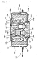
- Fig. 1 is a vertical cross sectional view of a gas generator for an air bag which is one embodiment of the present invention
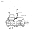
- Fig. 2 is a vertical cross sectional view of an igniter in Fig. 1
- Fig. 3 is a cross sectional view for explaining an inner structure of the igniter.
- Fig. 1 shows a pyrotechnic type gas generator for an air bag in which only a gas generated by combustion of a gas generating agent inflates an air bag.
- a substantially cylindrically-shaped inner cylindrical member 104 is arranged in a housing 103 formed by joining a diffuser shell 101 having a gas discharging port and a closure shell 102 forming an inner accommodating space together with the diffuser shell, and the outside thereof is defined as a first combustion chamber 105a.
- a stepped notch portion is provided inside the inner cylindrical member 104, a disk-like partition wall 107 is disposed at the stepped notch portion, and the space in the inner cylindrical member 104 is partitioned into two chambers by the partition wall 107 so that a second combustion chamber 105b is defined in the diffuser shell side (the upper space) and an ignition means is stored in the closure shell side (the lower space).
- Gas generating agents 109a and 109b which are burnt by the ignition means activated due to the impact to generate a combustion gas, are stored in the first and second combustion chambers 105a and 105b, and the ignition means is provided with a first igniter 112a and a second igniter 112b which are activated due to the impact for ignition.
- the first igniter 112a and the second igniter 112b are activated by the activation-signal outputted on the basis of that a sensor detects the impact, and they are provided in parallel to an initiator collar 113 serving as a holder, having their head portions exposed. Then, the first igniter 112a and the second igniter 112b are fixed to the initiator collar 113 by a metallic pressing member 130 from the above.
- the first igniter 112a has a grounding pin 181 [the negative electrode (or the positive electrode)] and a center pin 182 [the positive (electrode (or the negative electrode)].
- a bridge wire 119 which is a conductive wire such as an electric resistance wire or the like at the portions thereof contacting with a priming as shown in Fig. 3, the other end of the grounding pin 181 is connected to a metal portion of a motor vehicle via a connector to ground, while the other end of the center pin 182 is connected to an external power supply via the connector.
- the grounding pin 181 is connected to a metallic eyelet 195, and the center pin 182 is insulated from the metallic eyelet 195 by a glass 196.
- a bridge wire (electric resistance wire) 119 is connected between the one end of the center pin 182 and the eyelet, and the bridge wire 119 contacts with a priming 197.
- the first igniter 112a has a structure such that the priming 197 and a charge holder 121 are disposed inside a metallic cover member 164, and the cover member 164 and the eyelet 195 contact with each other. Also, the cover member 164 can be covered with a thin film developing an electrical insulation.
- the second igniter 112b has a grounding pin 191 (the negative electrode) and a center pin 192 (the positive electrode).
- a bridge wire 119 which is a conductive wire such as an electric resistance wire or the like at the portions thereof contacting with a priming 197, and the other end of the grounding pin 191 is connected to a metal portion of the motor vehicle via a connector to ground, while the other end of the center pin 192 is connected to an external power supply, via the connector.
- an opening/shutting means (a switch) of current (not shown) is provided between the center pin 192 and the external power supply: Furthermore, a part of the grounding pin 191 is connected to a metallic eyelet 195, and the center pin 192 is insulated from the metallic eyelet 195 by a glass 196. A bridge wire (electric resistance wire) 119 is connected between the one end of the center pin 192 and the eyelet, and the bridge wire 119 contacts with a priming 197. Thereby, when the center pin 192 is electrified, current flows through the bridge wire 119 so that the priming 197 is ignited.
- the second igniter 112b has a structure such that the priming 197 and a charge holder 121 are disposed inside a metallic cover member 164, and the cover member 164 and the eyelet 195 contact with each other. Also, the cover member 164 can be covered with a thin film developing an electrical insulation.
- a transfer charge 116 accommodated in an aluminum cup is disposed above the first igniter 112a, and the transfer charge 116 is separated from the second combustion chamber 105b by a substantially cylindrical partition member 140 (shown in the drawing) and the partition wall 107.
- a flame-transferring hole 117 is provided in the inner cylindrical member 104, and the hole is closed by a seal tape 118.
- a through-hole 110 is provided in the inner cylindrical member 104 defining the first combustion chamber 105a and the second combustion chamber 105b, and the through-hole is closed by a seal tape 111.
- the seal tape 111 is ruptured when the gas generating agent is burnt, both the combustion chambers can communicate with each other through the through-hole 110.
- An opening area of the through-hole 110 is larger than that of the gas discharging port 126, and it does not have a function for controlling the internal pressure in the second combustion chamber 105b.
- a common coolant/filter 122 for purifying and cooling combustion gases generated by combustion of the first and second gas generating agents 109a and 109b is disposed in the housing 103, and an inner circumferential surface of the filter 122 in the diffuser shell 101 side is covered with a short-pass preventing member 123.
- an outer layer 124 for suppressing expansion of the filter 122 due to passing of the combustion gas or the like is disposed outside the coolant/filter 122.
- the outer layer 124 can be made of, for example, a laminated wire mesh body.
- a gap 125 is formed outside the outer layer 124 so that the combustion gas can pass through all portions of the filter 122.
- a gas discharging port 126 formed in the diffuser shell is closed by a seal tape 127 in order to block the outside air.
- the metallic pressing member 130 may be broken by a pressure of that combustion and the broken portion may make a bridge between the first igniter 112a and the second igniter 112b.
- (+) current can flow in the second igniter 112b via the pressing member 130, or the pressing member 130 and the partition member 140.
- (+) current flows in the second igniter 112b in this manner, the (+) current flows in only the grounding pin 191, and it never flows in the center pin 192.
- the opening/shutting means of current between the center pin 192 of the second igniter 112b and the external power supply is open so that current never flows in the center pin 192.
- (+) current flows from the center pin 192 to the grounding pin 181 of the first igniter 112a through the bridge wire 119 and the bridging broken portion.
- the priming 197 is ignited so that the second igniter 112b may be activated erroneously.
- the center pin 192 of the second igniter 112b is set to the positive electrode and the opening/shutting means of current is provided between the center pin 192 and the external power supply, an erroneous activity of the second igniter 112b can be prevented unfailingly.
- FIG. 4 is a vertical cross sectional view of a gas generator for an air bag according to other embodiment of the present invention
- Fig. 5 is a vertical cross sectional view of the initiator assembly in Fig. 4.
- Fig. 4 shows a pyrotechnic type gas generator for an air bag in which only a gas generated by combustion of a gas generating agent inflates an air bag.
- This gas generator is different in an ignition means from the gas generator for an air bag shown in Fig. 1, but is approximately identical to the same in the other portions, so that only the ignition means will be explained.
- the ignition means includes an initiator assembly 10 and a transfer charge 116 filled in an aluminum cup.
- the initiator assembly 10 is fitted into an inner cylindrical member 104 (in the space formed by the inner cylindrical member 104 and the partition wall 107), and it is mounted thereto by crimping a lower end portion 104a of the inner cylindrical member 104.
- the initiator assembly 10 includes a first igniter 32a, a second igniter 32b and a collar assembly 31.
- the collar assembly 31 includes a resin portion 36 made of a molding plastic material as a injection-molded insulating material and a metallic collar 40, and the base portions of the first igniter 32a and the second igniter 32b are surrounded by the resin portion 36.
- the metallic collar 40 is joined to the resin portion 36.
- an injection-molding process is employed for joining the collar assembly 31 comprising the resin portion 36 and the metallic collar 40 integrally with the first igniter 32a and the second igniter 32b.
- liquid-like or fluidized molding plastic material constituting the resin portion 36 is filled in between the base portions of the first igniter 32a and the second igniter 32b and the metallic collar 40.
- the metallic collar 40 is fixed on and retained to the resin portion 36, and the resin portion 36 is fixed on and retained to the first igniter 32a and the second igniter 32b.
- a groove 202 is formed around a lower end portion of the metallic collar 40 of the initiator assembly 10, and an O-ring made of rubber, plastic or the like is fitted in the groove 202. Then, by arranging the O-ring 200 in this manner, moisture is prevented fr,om entering from the contacting portion between the inner cylindrical member 104 and the initiator assembly 10 (metallic collar 40), so that the interior of the gas generator for an air bag is kept in a moisture-proof state. Thus, since the interior is kept in the moisture-proof state, the performance of the gas generating agents 109a and 109b is prevented from deteriorating due to moisture absorption.
- the initiator assembly 10 includes the first initiator 32a and the second initiator 32b, but it is sufficient to provide only one O-ring 200, so that the number of manufacturing steps for the initiator assembly 10 is not increased as compared with that for a gas generator having a single initiator and moisture-proof of the former is substantially equal to that of the latter.
- the first igniter 32a and the second igniter 32b include a metallic eyelet (end plate) 46 in which a hole 50 is formed.
- the first igniter 32a has a center pin 54a [the positive electrode (or the negative electrode)] and a grounding pin 70a [the negative electrode (or the positive electrode)], while the second igniter 32b has a center pin 54b (the positive electrode) and a grounding pin 70b (the negative electrode).
- an unillustrated opening/shutting means of current is provided between the center pin 54b and an external power supply.
- bridge wires which are conductive wires such as electric resistance wires are disposed respectively between the center pins 54a and 54b and the eyelets 46, contacting with the priming 62.
- the cover member 64 may be covered with a thin film developing an electrical insulation.
- center pins 54a and 54b go through holes 50, and the center pins 54a and 54b are positioned, insulated against the metallic eyelets 46 by glasses 33 corresponding to an electrical insulating body.
- the center pins 54a and 54b transmit ignition signals for igniting the priming 62.
- the cover member 64 comprising a metal wall encloses or covers the priming 62 filled in the charge holder 21 and it is welded to the eyelet 46. It is preferable that a circular end portion of the cover member 64 is provided with notches so that it can be broken easily and unfailingly. Such notches can be formed as grooves of about 0.10 to 0.25 mm radially, in case that the cover member 64 is made of stainless steel (SUS305).
- the grounding pins 70a and 70b are insulated from the center pins 54a and 54b by glasses 33.
- the resin portion 36 made of molding plastic material surrounds the metallic eyelets 46 of the first igniter 32a and 'the second igniter 32b, the center pins 54a, 54b and the grounding pins 70a, 70b, and in addition, the metallic collar 40 is mounted to the outside of the resin portion 36.
- the resin portion 36 is resin-molded integrally, including the metallic collar 40. At this time, the end surfaces of the center pins 54a and 54b, the eyelets 46, the glasses 33 holding the center pins 54a and 54b in the holes 50 of the eyelets 46 are put on the same plane.
- a front end peripheral surface of the resin portion 36 and a front end peripheral surface of the metallic collar 40 surrounding the resin portion 36 form a continuous circumferential surface to be frictionally fitted into the inner cylindrical member 104 shown in Fig. 4, and a projection 42 is formed on a front end peripheral surface of the resin portion 36.
- the projection 42 increase the friction between the inner cylindrical member 104 and the initiator assembly 10, prevents rattling or rotation of the initiator assembly 10, and facilitates a crimping process of the inner cylindrical member 104.
- the base portion of the resin portion 36 through which the center pins 54a, 54b and the grounding pins 70a, 70b pass insulates the metallic collar 40 from the center pins 54a, 54b and the grounding pins 70a, 70b.
- the metallic collar 40 has cavities 85 inside, and a surface of the cavity 85 is not covered with the molding plastic material and the metallic collar is exposed.
- the tip end portions of the center pins 54a, 54b and the grounding pins 70a, 70b protrude in the cavities 85 but the tip end portions are not exposed out of the cavities 85 of the metallic collars 40. This is for preventing the pins from being deformed during assembling the initiator.
- Connectors 23a and 23b shown with a chain line in the drawing are fitted into and connected to the cavities 85. That is, the inside of the cavity 85 serves as a connecting portion in which the connector is fitted.
- a recessed notch 88 is provided inside the end portion of the connector connecting cavity 85 of the metallic collar 40 in the circumferential direction, thereby forming a falling-out preventing means for the fitted connector.
- the current flows through the grounding pin 70a via the bridge wire 19, the priming 62 is ignited and burnt in the course, and then the transfer charge 116 is ignited and burnt. Consequently, the seal tape 118 is ruptured by a high temperature gas generated by combustion of the transfer charge 116, the high temperature gas enters the first combustion chamber 105a through the flame-transferring holes 117, and the first gas generating agent 109a is ignited and burnt to generate a gas.
- the metallic pressing member 130 may be broken by a pressure of that combustion and the broken portion may make a bridge between the first igniter 112a and the second igniter 112b.
- (+) current can flow in the second igniter 112b via the pressing member 130, or the pressing member 130 and the partition member 140.
- (+) current flows in the second igniter 32b in this manner, the (+) current flows in only the grounding pin 70b, and it never flows in the center pin 54b.
- the opening/shutting means of current between the center pin 54b of the second igniter 32b and the external power supply is open so that current is prevented from flowing in the center pin 54b.
- (+) current flows from the center pin 54b to the grounding pin 54b of the first igniter 32a through the bridge wire 19 and the bridging broken portion.
- the priming 62 is ignited so that the second igniter 32b may be activated erroneously.
- the center pin 54b of the second igniter 32b is set to the positive electrode and the opening/shutting means of current is provided between the center pin 54b and the external power supply, an erroneous activity of the second igniter 112b can be prevented unfailingly.
- the air bag system according to the present invention can use the pyrotechnic type gas generators shown in Fig. 1 and Fig. 4. Naturally, any gas generator according to the present invention can be used regardless of whether the gas generator is pyrotechnic or not.
- the air bag system is provided with an activation-signal outputting means comprising an impact sensor and a control unit, and a module case in which the gas generator and an air bag are accommodated.
- the gas generator is connected to the activation-signal outputting means (the impact sensor and the control unit) in the side where the first igniter 117 and the second igniter 140 are provided.
- an inflating speed of the air bag can be adjusted in accordance to a degree of the impact by activating only the first igniter 117, or activating the first igniter 117 and the second igniter 140 at different timings, or activating two igniters.
- FIG. 6 shows one embodiment of the air bag system of the present invention.
- the air bag system comprises a gas generator 200, an impact sensor 201, a control unit 202, a module case 203 and an air bag 204.
- the gas generator 200 the gas generator described with reference to Fig. 1 is used, and the activating performance thereof is adjusted to give as little an impact as possible to an at the initial stage in the activation of the gas generator.
- the impact sensor 201 can comprise, for example, a semiconductor type acceleration sensor.
- a semiconductor type acceleration sensor In this semiconductor type acceleration sensor, four semiconductor strain gauges are formed on a beam of a silicon substrate to be bent when acceleration is applied, and these semiconductor strain gauges are bridge-connected. When an acceleration is applied, the beam defects and a strain is produced the surface. The resistances of the semiconductor strain gauges are changed due to this strain, the resistance change is detected as a voltage signal proportional to the acceleration.
- the control unit 202 is provided with an ignition-judgement circuit, and a signal from the semiconductor type acceleration sensor is inputted to the ignition-judgement circuit.
- the control unit 202 starts calculation at a time when the impact signal from the sensor 201 exceeds a predetermined, value and, when the calculated result exceeds a predetermined value, a activation-signal is outputted to the igniter of the gas generator 200, namely, the first igniter 117 or the second igniter 140.
- the module case 203 is made of, for example, polyurethane and it includes a module cover 205.
- the air bag 204 and the gas generator 200 are accommodated in the module case 203 to be constituted as a pad module.
- the pad module is ordinarily mounted to a steering wheel 207 when it is mounted in a driver side in an automobile.
- the air bag 204 is made of nylon (for example, nylon 66), polyester or the like, the opening 206 thereof surrounds a gas discharging port of the gas generator, and the air bag is fixed to a flange portion of the gas generator in a folded state.
- the semiconductor type acceleration sensor 201 senses an impact at a time of collision of an automobile
- the detection signal is transmitted to the control unit 202, and when the impact signal from the sensor exceeds the predetermined value, the control unit 202 starts calculation.
- a working signal is output to the first igniter 117 or the second igniter 140 of the gas generator 200.
- the igniter is activated to ignite the gas generating agent so that the gas generating agent is burnt to generate gas.
- This gas is inj ected to the air bag 204 and thereby the air bag breaks the module cover 205 to inflate so that a cushion absorbing the impact is formed between the steering wheel 207 and the occupant.
Landscapes
- Engineering & Computer Science (AREA)
- Physics & Mathematics (AREA)
- Fluid Mechanics (AREA)
- Mechanical Engineering (AREA)
- General Engineering & Computer Science (AREA)
- Air Bags (AREA)
- Feeding, Discharge, Calcimining, Fusing, And Gas-Generation Devices (AREA)
Abstract
Claims (7)
- Générateur de gaz pour un coussin de sécurité gonflable comprenant, dans un boîtier (103) possédant un orifice d'évacuation de gaz, un moyen d'allumage équipé de premier et second allumeurs (32a, 32b; 112a, 112b; 217, 240), incluant une amorce (62) activée par le choc, et un moyen de production de gaz allumé et brûlé par le moyen d'allumage (109a, 109b) pour générer un gaz de combustion, dans lequel:les premier et second allumeurs (32a, 32b; 112a, 112b; 217, 240) sont montés en parallèle dans le boîtier au moyen d'un support;dans le second allumeur (32b; 112b; 240), une broche centrale (54a, 54b; 182, 192; 217a, 240a) est raccordée à une source d'alimentation externe pour constituer l'électrode positive, une broche de mise à la masse (70a, 70b; 181, 191; 217b, 240b) est raccordée à une partie métallique d'un véhicule automobile pour constituer l'électrode négative, etles premier et second allumeurs (32a, 32b; 112a, 112b; 217, 240) sont fixés au dispositif (113) de support des allumeurs au moyen d'un élément métallique de serrage (130),caractérisé en ce que un moyen d'ouverture / de fermeture du courant est prévu entre la broche centrale (54a, 54b; 182, 192; 217a, 240a) et la source d'alimentation externe, la broche de mise à la masse (70a, 70b; 181, 191; 217b, 240b) étant connectée électriquement à une partie métallique constituant une enceinte en forme de coque extérieure de l'allumeur, etdans lequel la broche centrale (54a, 54b; 182, 192; 217a, 240a) est connectée électriquement à la broche de mise à la masse (70a, 70b; 181, 191; 217b, 240b) par l'intermédiaire uniquement d'un fil formant résistance électrique (119).
- Générateur de gaz pour un coussin de sécurité gonflable selon la revendication 1, dans lequel le moyen d'allumage, qui est équipé des premier et second allumeurs (32a, 32b; 112a, 112b; 217, 240) incluant l'amorce (62) activée par le choc, inclut un ensemble déclencheur (10) activé par le choc et une charge de transfert, et les premier et second allumeurs (32a, 32b; 112a, 112b; 217, 240) incluent chacun au moins une broche conductrice pour allumer l'amorce (62), le support (113) comprenant un ensemble à collet (113) pour fixer l'ensemble déclencheur (10) au générateur de gaz, et l'ensemble à collet (113) comprend un matériau isolant entourant au moins une des parties des premier et second allumeurs respectifs (32a, 32b; 112a, 112b; 217, 240), et un collet réuni au matériau isolant.
- Générateur de gaz pour un coussin de sécurité gonflable selon la revendication 2, dans lequel, dans l'ensemble déclencheur (10), les surfaces d'extrémité d'au moins une broche conductrice, d'un oeillet métallique (46, 195) de l'allumeur comportant un trou (50) par lequel passe la broche conductrice, et un corps électriquement isolant (33) servant à isoler la broche conductrice insérée dans le trou (50) à partir de l'oeillet (46, 195) sont disposés dans le même plan.
- Générateur de gaz pour un coussin de sécurité gonflable selon l'une quelconque des revendications 1 à 3, dans lequel le générateur de gaz pour un coussin de sécurité gonflable possède une structure telle qu'un coussin de sécurité gonflable est gonflé uniquement par un gaz de combustion produit par le moyen de production de gaz.
- Générateur de gaz pour un coussin de sécurité gonflable selon l'une quelconque des revendications 1 à 4, dans lequel le second allumeur (32b; 112b; 240) est adapté pour être activé en même temps que le premier allumeur (32a; 112a; 217) ou après le premier allumeur (32a; 112a; 217).
- Système de coussin de sécurité gonflable comprenant un générateur de gaz (200) pour un coussin de sécurité gonflable (204), un détecteur de choc (201) pour détecter le choc pour activer le générateur de gaz (200), un coussin de sécurité gonflable (204) dans lequel est introduit un gaz généré par le générateur de gaz (200) et/ou un fluide sous pression pour réaliser un gonflage, et un boîtier de module (203) logeant le coussin de sécurité gonflable (204), le générateur de gaz (200) pour un coussin de sécurité gonflable (204) étant le générateur de gaz (200) pour un coussin de sécurité gonflable (204) selon l'une quelconque des revendications 1 à 5.
- Procédé pour recevoir un signal d'activation dans un générateur de gaz pour un coussin de sécurité gonflable, consistant à:prévoir, dans un boîtier (103) du générateur de gaz, un premier allumeur (32a; 112a; 217) et un second allumeur (32b; 112b; 240) montés en parallèle et activés par un signal d'activation électrique par l'intermédiaire d'un dispositif de support;prévoir, dans le second allumeur (32b; 112b; 240), une broche centrale (54a, 54b; 182, 192; 217a, 240a) connectée à une source d'alimentation externe pour constituer une électrode positive;prévoir, dans le second allumeur (32b; 112b; 240) une broche de mise à la masse (70a, 70b; 181, 191; 217b, 240b) connectée à une partie métallique d'un véhicule automobile pour constituer l'électrode négative, etfixer le premier allumeur (32a; 112a; 217) et le second allumeur (32b; 112b; 240) au moyen d'un élément métallique de serrage (130);caractérisé en ce que le procédé consiste en outre à:prévoir un moyen d'ouverture / de fermeture pour un courant entre la broche centrale (54a, 54b; 182, 192; 217a, 240a) et la source d'alimentation externe, la broche de mise à la masse (70a, 70b; 181, 191; 217b, 240b) étant connectée électriquement à une partie métallique constituant une enceinte en forme de coque extérieure de l'allumeur, etdans lequel la broche centrale (54a, 54b; 182, 192; 217a, 240a) est connectée à la broche de mise à la masse (70a, 70b; 181, 191; 217b, 240b) par l'intermédiaire uniquement d'un fil formant résistance électrique (119).
Applications Claiming Priority (5)
| Application Number | Priority Date | Filing Date | Title |
|---|---|---|---|
| JP2000187147 | 2000-06-22 | ||
| JP2000187147 | 2000-06-22 | ||
| JP2001185440 | 2001-06-19 | ||
| JP2001185440A JP4864234B2 (ja) | 2000-06-22 | 2001-06-19 | エアバッグ用ガス発生器 |
| PCT/JP2001/005321 WO2001098114A1 (fr) | 2000-06-22 | 2001-06-21 | Producteur de gaz pour coussin de securite gonflable |
Publications (3)
| Publication Number | Publication Date |
|---|---|
| EP1293394A1 EP1293394A1 (fr) | 2003-03-19 |
| EP1293394A4 EP1293394A4 (fr) | 2004-08-18 |
| EP1293394B1 true EP1293394B1 (fr) | 2006-04-19 |
Family
ID=26594427
Family Applications (1)
| Application Number | Title | Priority Date | Filing Date |
|---|---|---|---|
| EP01941160A Expired - Lifetime EP1293394B1 (fr) | 2000-06-22 | 2001-06-21 | Producteur de gaz pour coussin de securite gonflable |
Country Status (6)
| Country | Link |
|---|---|
| US (1) | US6848713B2 (fr) |
| EP (1) | EP1293394B1 (fr) |
| JP (1) | JP4864234B2 (fr) |
| DE (1) | DE60118915T2 (fr) |
| TW (1) | TW531505B (fr) |
| WO (1) | WO2001098114A1 (fr) |
Families Citing this family (27)
| Publication number | Priority date | Publication date | Assignee | Title |
|---|---|---|---|---|
| CZ20033416A3 (en) * | 2001-05-15 | 2004-04-14 | Nippon Kayaku Kabushiki-Kaisha | Gas generator |
| BRPI0311647A2 (pt) * | 2002-06-07 | 2016-06-28 | Autoliv Dev | disposição de fixação eletricamente isolada para um módulo de air-bag |
| DE10225384C1 (de) * | 2002-06-07 | 2003-11-27 | Guenter Duerschinger | Zündvorrichtung für den Gasgenerator eines Insassen-Rückhaltesystems in einem Kraftfahrzeug |
| US7293797B2 (en) * | 2002-10-07 | 2007-11-13 | Daicel Chemical Industries, Ltd. | Inflator |
| US20040155444A1 (en) * | 2002-12-09 | 2004-08-12 | Naoki Matsuda | Gas generator for air bag |
| DE20300346U1 (de) * | 2003-01-10 | 2003-05-15 | TRW Airbag Systems GmbH, 84544 Aschau | Hybrid-Gasgenerator |
| DE20309360U1 (de) * | 2003-06-17 | 2003-10-23 | TRW Automotive Safety Systems GmbH, 63743 Aschaffenburg | Gasgeneratorbaugruppe |
| US7077428B2 (en) * | 2003-07-07 | 2006-07-18 | Autoliv Asp, Inc. | Airbag initiator cover attachment apparatus and method |
| US7665764B2 (en) * | 2004-01-15 | 2010-02-23 | Daicel Chemical Industries, Ltd. | Gas generator for air bag |
| JP2005225346A (ja) * | 2004-02-12 | 2005-08-25 | Daicel Chem Ind Ltd | エアバッグ用インフレータ |
| JP4407430B2 (ja) * | 2004-08-27 | 2010-02-03 | トヨタ自動車株式会社 | 自動車 |
| EP1669257B1 (fr) * | 2004-12-08 | 2007-04-25 | Delphi Technologies, Inc. | Générateur de gaz |
| US20070001439A1 (en) * | 2005-06-16 | 2007-01-04 | Daicel Chemical Industries, Ltd. | Gas generator for air bag |
| US7597353B2 (en) * | 2006-05-25 | 2009-10-06 | Autoliv Asp, Inc. | Inflator device having an annular inflation gas discharge opening |
| US7950693B2 (en) * | 2008-05-20 | 2011-05-31 | Autoliv Asp, Inc. | Dual stage inflator |
| DE102008060305A1 (de) | 2008-12-03 | 2010-06-10 | Trw Airbag Systems Gmbh | Gasgenerator |
| US8375862B2 (en) * | 2008-12-04 | 2013-02-19 | Tk Holdings, Inc. | Gas generating system |
| US8047569B2 (en) * | 2010-03-12 | 2011-11-01 | Autoliv Asp, Inc. | Multi-stage inflator |
| FR2960958B1 (fr) * | 2010-06-02 | 2012-06-22 | Livbag | Generateur de gaz et son procede de fabrication |
| JP5985950B2 (ja) * | 2012-10-04 | 2016-09-06 | 株式会社ダイセル | ガス発生器とその組立方法 |
| US9290419B2 (en) | 2012-11-29 | 2016-03-22 | Autoliv Asp, Inc. | Duplex actuation system for inflatable restraints |
| US9248802B2 (en) | 2012-11-29 | 2016-02-02 | Autoliv Asp, Inc. | Surface mount initiators |
| US10267605B1 (en) * | 2014-09-30 | 2019-04-23 | Reynolds Systems, Inc. | High G-force resistant initiator assembly having an exploding foil initiator |
| US10920544B2 (en) | 2017-08-09 | 2021-02-16 | Geodynamics, Inc. | Setting tool igniter system and method |
| US10036236B1 (en) | 2017-08-09 | 2018-07-31 | Geodynamics, Inc. | Setting tool igniter system and method |
| US10605576B1 (en) * | 2017-10-16 | 2020-03-31 | Reynolds Systems, Inc. | Dual mode initiator system |
| EP4406788A4 (fr) | 2021-09-22 | 2025-09-03 | Daicel Corp | Générateur de gaz |
Family Cites Families (10)
| Publication number | Priority date | Publication date | Assignee | Title |
|---|---|---|---|---|
| JPS5215845B1 (fr) * | 1970-03-24 | 1977-05-04 | ||
| US5404263A (en) * | 1992-08-27 | 1995-04-04 | Oea, Inc. | All-glass header assembly used in an inflator system |
| JP3702074B2 (ja) | 1997-08-25 | 2005-10-05 | 日本化薬株式会社 | ガス発生器 |
| JP3986184B2 (ja) * | 1997-11-05 | 2007-10-03 | 日本化薬株式会社 | ガス発生器 |
| US6007096A (en) | 1998-04-20 | 1999-12-28 | Trw Inc. | Inflator having a pressure monitoring initiator |
| ATE258124T1 (de) * | 1998-09-28 | 2004-02-15 | Daicel Chem | Luftsack-gasgenerator und luftsacksystem |
| US6315322B1 (en) * | 1999-03-05 | 2001-11-13 | Trw Inc. | Air bag inflator |
| CZ2002120A3 (cs) * | 1999-07-12 | 2002-05-15 | Nippon Kayaku Kabushiki-Kaisha | Vyvíječ plynu |
| KR100511120B1 (ko) * | 1999-07-28 | 2005-08-31 | 니뽄 가야쿠 가부시키가이샤 | 가스 발생기에서 점화기와 차량측 커넥터 사이의 오접속을 판단하는 방법 |
| JP2001163169A (ja) * | 2000-12-19 | 2001-06-19 | Daicel Chem Ind Ltd | エアバッグ用ガス発生器の点火手段 |
-
2001
- 2001-06-19 JP JP2001185440A patent/JP4864234B2/ja not_active Expired - Lifetime
- 2001-06-21 WO PCT/JP2001/005321 patent/WO2001098114A1/fr not_active Ceased
- 2001-06-21 US US10/275,004 patent/US6848713B2/en not_active Expired - Lifetime
- 2001-06-21 EP EP01941160A patent/EP1293394B1/fr not_active Expired - Lifetime
- 2001-06-21 TW TW090115077A patent/TW531505B/zh not_active IP Right Cessation
- 2001-06-21 DE DE60118915T patent/DE60118915T2/de not_active Expired - Lifetime
Also Published As
| Publication number | Publication date |
|---|---|
| JP4864234B2 (ja) | 2012-02-01 |
| US6848713B2 (en) | 2005-02-01 |
| EP1293394A4 (fr) | 2004-08-18 |
| US20030184068A1 (en) | 2003-10-02 |
| DE60118915T2 (de) | 2006-08-31 |
| JP2002079903A (ja) | 2002-03-19 |
| WO2001098114A1 (fr) | 2001-12-27 |
| EP1293394A1 (fr) | 2003-03-19 |
| DE60118915D1 (de) | 2006-05-24 |
| TW531505B (en) | 2003-05-11 |
Similar Documents
| Publication | Publication Date | Title |
|---|---|---|
| EP1293394B1 (fr) | Producteur de gaz pour coussin de securite gonflable | |
| US6718884B1 (en) | Initiator assembly | |
| US6669230B1 (en) | Multistage gas generator for air bag and air bag apparatus | |
| US5241910A (en) | Universal squib connector for a gas generator | |
| US7152874B2 (en) | Gas generator for air bag and air bag apparatus | |
| US6936303B1 (en) | Electric type initiator and gas generator | |
| JP2535125B2 (ja) | 電気コネクタ結合用装置 | |
| EP1447641B2 (fr) | Ensemble initiateur | |
| EP0512682B1 (fr) | Connexion universelle pour capsule détonante | |
| US6820556B1 (en) | Initiator assembly | |
| EP1286125A1 (fr) | Ensemble initiateur et generateur de gaz utilisant cet initiateur | |
| JPH04266548A (ja) | エアーバック膨張装置 | |
| US6257910B1 (en) | Shorting clip for air bag inflator | |
| WO2022239790A1 (fr) | Ensemble allumeur et dispositif de génération de gaz | |
| JP2010513106A (ja) | 自動車のエアバッグ・モジュール用ガス発生器アセンブリ | |
| JP2000329500A (ja) | スクイブ | |
| EP1201512A1 (fr) | Generateur de gaz | |
| JP4425429B2 (ja) | 多段式エアバッグ装置及びそれに用いるガス発生器 | |
| JP2001277990A (ja) | エアバッグ用ガス発生器 | |
| JP2001080447A (ja) | ガス発生器 | |
| JPWO2001031281A1 (ja) | 電気式イニシエーターとガス発生器 |
Legal Events
| Date | Code | Title | Description |
|---|---|---|---|
| PUAI | Public reference made under article 153(3) epc to a published international application that has entered the european phase |
Free format text: ORIGINAL CODE: 0009012 |
|
| 17P | Request for examination filed |
Effective date: 20021210 |
|
| AK | Designated contracting states |
Kind code of ref document: A1 Designated state(s): AT BE CH CY DE DK ES FI FR GB GR IE IT LI LU MC NL PT SE TR |
|
| RBV | Designated contracting states (corrected) |
Designated state(s): AT BE CH DE FR GB LI |
|
| A4 | Supplementary search report drawn up and despatched |
Effective date: 20040706 |
|
| RIC1 | Information provided on ipc code assigned before grant |
Ipc: 7B 60R 21/26 B Ipc: 7F 42B 3/12 B Ipc: 7B 60R 21/01 A Ipc: 7B 60R 21/32 B |
|
| 17Q | First examination report despatched |
Effective date: 20040907 |
|
| GRAP | Despatch of communication of intention to grant a patent |
Free format text: ORIGINAL CODE: EPIDOSNIGR1 |
|
| RBV | Designated contracting states (corrected) |
Designated state(s): DE FR GB |
|
| GRAS | Grant fee paid |
Free format text: ORIGINAL CODE: EPIDOSNIGR3 |
|
| GRAA | (expected) grant |
Free format text: ORIGINAL CODE: 0009210 |
|
| AK | Designated contracting states |
Kind code of ref document: B1 Designated state(s): DE FR GB |
|
| REG | Reference to a national code |
Ref country code: GB Ref legal event code: FG4D |
|
| RIC1 | Information provided on ipc code assigned before grant |
Ipc: B60R 21/26 20060101ALI20060302BHEP Ipc: B60R 21/01 20060101AFI20060302BHEP Ipc: F42B 3/12 20060101ALI20060302BHEP Ipc: B60R 21/16 20060101ALI20060302BHEP |
|
| REF | Corresponds to: |
Ref document number: 60118915 Country of ref document: DE Date of ref document: 20060524 Kind code of ref document: P |
|
| ET | Fr: translation filed | ||
| PLBE | No opposition filed within time limit |
Free format text: ORIGINAL CODE: 0009261 |
|
| STAA | Information on the status of an ep patent application or granted ep patent |
Free format text: STATUS: NO OPPOSITION FILED WITHIN TIME LIMIT |
|
| 26N | No opposition filed |
Effective date: 20070122 |
|
| PGFP | Annual fee paid to national office [announced via postgrant information from national office to epo] |
Ref country code: GB Payment date: 20100616 Year of fee payment: 10 |
|
| REG | Reference to a national code |
Ref country code: FR Ref legal event code: ST Effective date: 20110228 |
|
| PG25 | Lapsed in a contracting state [announced via postgrant information from national office to epo] |
Ref country code: FR Free format text: LAPSE BECAUSE OF NON-PAYMENT OF DUE FEES Effective date: 20100630 |
|
| GBPC | Gb: european patent ceased through non-payment of renewal fee |
Effective date: 20110621 |
|
| PG25 | Lapsed in a contracting state [announced via postgrant information from national office to epo] |
Ref country code: GB Free format text: LAPSE BECAUSE OF NON-PAYMENT OF DUE FEES Effective date: 20110621 |
|
| PGFP | Annual fee paid to national office [announced via postgrant information from national office to epo] |
Ref country code: FR Payment date: 20090611 Year of fee payment: 9 |
|
| PGFP | Annual fee paid to national office [announced via postgrant information from national office to epo] |
Ref country code: DE Payment date: 20200618 Year of fee payment: 20 |
|
| REG | Reference to a national code |
Ref country code: DE Ref legal event code: R071 Ref document number: 60118915 Country of ref document: DE |