EP1293465B1 - Zielregistriereinrichtung für aufzug - Google Patents
Zielregistriereinrichtung für aufzug Download PDFInfo
- Publication number
- EP1293465B1 EP1293465B1 EP00940781A EP00940781A EP1293465B1 EP 1293465 B1 EP1293465 B1 EP 1293465B1 EP 00940781 A EP00940781 A EP 00940781A EP 00940781 A EP00940781 A EP 00940781A EP 1293465 B1 EP1293465 B1 EP 1293465B1
- Authority
- EP
- European Patent Office
- Prior art keywords
- destination
- information
- input
- elevator
- registering
- Prior art date
- Legal status (The legal status is an assumption and is not a legal conclusion. Google has not performed a legal analysis and makes no representation as to the accuracy of the status listed.)
- Expired - Lifetime
Links
Images






Classifications
-
- B—PERFORMING OPERATIONS; TRANSPORTING
- B66—HOISTING; LIFTING; HAULING
- B66B—ELEVATORS; ESCALATORS OR MOVING WALKWAYS
- B66B1/00—Control systems of elevators in general
- B66B1/34—Details, e.g. call counting devices, data transmission from car to control system, devices giving information to the control system
- B66B1/46—Adaptations of switches or switchgear
- B66B1/461—Adaptations of switches or switchgear characterised by their shape or profile
- B66B1/462—Mechanical or piezoelectric input devices
-
- B—PERFORMING OPERATIONS; TRANSPORTING
- B66—HOISTING; LIFTING; HAULING
- B66B—ELEVATORS; ESCALATORS OR MOVING WALKWAYS
- B66B1/00—Control systems of elevators in general
- B66B1/34—Details, e.g. call counting devices, data transmission from car to control system, devices giving information to the control system
- B66B1/46—Adaptations of switches or switchgear
- B66B1/468—Call registering systems
-
- B—PERFORMING OPERATIONS; TRANSPORTING
- B66—HOISTING; LIFTING; HAULING
- B66B—ELEVATORS; ESCALATORS OR MOVING WALKWAYS
- B66B3/00—Applications of devices for indicating or signalling operating conditions of elevators
-
- B—PERFORMING OPERATIONS; TRANSPORTING
- B66—HOISTING; LIFTING; HAULING
- B66B—ELEVATORS; ESCALATORS OR MOVING WALKWAYS
- B66B3/00—Applications of devices for indicating or signalling operating conditions of elevators
- B66B3/002—Indicators
- B66B3/006—Indicators for guiding passengers to their assigned elevator car
-
- B—PERFORMING OPERATIONS; TRANSPORTING
- B66—HOISTING; LIFTING; HAULING
- B66B—ELEVATORS; ESCALATORS OR MOVING WALKWAYS
- B66B2201/00—Aspects of control systems of elevators
- B66B2201/40—Details of the change of control mode
- B66B2201/46—Switches or switchgear
- B66B2201/4607—Call registering systems
- B66B2201/4623—Wherein the destination is registered after boarding
-
- B—PERFORMING OPERATIONS; TRANSPORTING
- B66—HOISTING; LIFTING; HAULING
- B66B—ELEVATORS; ESCALATORS OR MOVING WALKWAYS
- B66B2201/00—Aspects of control systems of elevators
- B66B2201/40—Details of the change of control mode
- B66B2201/46—Switches or switchgear
- B66B2201/4607—Call registering systems
- B66B2201/463—Wherein the call is registered through physical contact with the elevator system
Definitions
- the present invention relates to a destination registering apparatus for an elevator, which is installed at an elevator hall or in a car for registering the destination of the car.
- Such an apparatus may be utilized in an elevator installed in a department store or the like, and users can confirm in the car the layout of a whole floor including retail areas and routes from the car to a retail area by registering the retail area as the destination point.
- the above described apparatus it is undesirable for the above described apparatus to be utilized as is in an elevator installed, for example, in a hotel, because the display can be seen by all the passengers in the car and a destination point, i.e., the room number and position of the guest room can be seen by a stranger if the stranger is in the car. Further, since the layout and the route are only displayed for a short time just before the car arrives at the destination floor, there is a strong possibility that the user will forget to look at the display when there is an extended period time between registering the destination point at the elevator hall and arrival at the destination floor.
- the present invention is made to solve the problems mentioned above, and an object of the present invention is to provide a destination registering apparatus for an elevator, which can display the layout of a destination floor and the route to a destination point preferentially to a passenger who has input the destination point.
- a destination registering apparatus for an elevator comprising: an input device for inputting information assigning a destination point, provided at an elevator hall; a storage device storing layout information for every floor and information of routes from the elevator halls of every floor to every destination point; a selection circuit for selecting information corresponding to the destination point input to the input device from information stored in the storage device; a hall display device for displaying information selected by the selection circuit, provided at the elevator hall; and a CPU for outputting destination registering signals to an elevator control device and outputting information selecting signals to the selection circuit according to the information input by the input device.
- a destination registering apparatus for an elevator comprising: an input device for inputting information assigning a destination point, provided in a car; a car operating panel having a car display device for displaying an image to a passenger who has operated the input device; a storage device storing layout information for every floor and information of routes from the elevator halls of every floor to every destination point; a selection circuit for selecting information corresponding to the destination point input to the input device from information stored in the storage device to display the information on the car display device; and a CPU for outputting destination registering signals to an elevator control device and outputting information selecting signals to the selection circuit according to the information input by the input device.
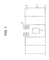
- Fig. 1 is a front view showing an elevator hall according to a first embodiment of the present invention. More particularly an elevator installed at a hotel will be described below.
- a plurality of hall entrances 1 are provided at an elevator hall. Each hall entrance 1 is opened and closed by a plurality of landing doors 2.
- a plurality of direction lamps 3 showing moving directions of corresponding cars (not shown) are provided nearby the hall entrances 1. Further, a hall operating panel 4 is disposed below the direction lamps 3.
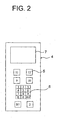
- Fig. 2 is a front view showing the hall operating panel in Fig. 1 .
- the hall operating panel 4 is provided with destination floor buttons 5 for designating destination floors, a ten-key numerical input device 6 for inputting room numbers as destination points, and a hall display device 7 for displaying images to users who have operated the ten-key numerical input device 6.
- the operations of the elevator for guest room floors used only by staying guests are controlled by the ten-key numerical input device 6. Further, the operations of the elevator for floors such as a reception desk floor, a restaurant floor and the like, also used by general users are controlled by the destination floor buttons 5.
- FIG. 3 is a block diagram showing a destination registering apparatus according to the first embodiment.
- a storage device 8 stores layout information for every floor and information of routes from the halls of every floor to every destination point.
- the information corresponding to the destination point input to the destination floor buttons 5 or the ten-key numerical input device 6 is selected by a selection circuit 9 from the information stored in the storage device 8 and displayed on the hall display device 7.
- Signals from the destination floor buttons 5 and the ten-key numerical input device 6 are input to a CPU (central processing unit) 10. signals for registering the destinations are output to an elevator control device 11 by the CPU 10 in accordance with the input information. Also, signals for selecting the information are output to the selection circuit 9 by the CPU 10.
- the ten-key numerical input device 6 is connected with a guest room information registering device 12 in which room numbers of available rooms are registered.
- a destination registering apparatus 13 has the destination floor buttons 5, the ten-key numerical input device 6, the hall display device 7, the storage device 8, the selection circuit 9 and the CPU 10.
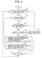
- Fig. 4 is a flow chart showing a control method of the destination registering apparatus in Fig. 3 .
- display contents such as input waiting messages such as "please enter a destination” or the like, or information on events in a building, are displayed on the hall display device 7 during standby mode (step S1).
- step S2 display contents
- step S3 it is normally checked to see whether a destination floor button 5 is pushed or not (stepS2), or whether the room number is input to the ten-key numerical input device 6 (step S3). If no input is received from either the destination floor buttons 5 or the ten-key numerical input device 6, the standby mode display continues.
- a destination floor button 5 is pushed, a call is registered in the elevator control device 11, the input floor is temporarily registered in the elevator control device 11 as the destination floor, and the layout of the input floor is displayed on the hall display device 7 (step S4).
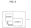
- Fig. 5 is a front view showing an example of the display contents of the hall display device 7 when the destination floor buttons 5 in Fig. 2 are pushed.
- the layout of a restaurant floor is displayed on the hall display device 7.
- Such a display of the layout is performed only for a time previously set in a timer circuit in the selection circuit 9 (step S5), and the display on the hall display device 7 reverts back to the contents for standby mode after the set time passes.
- step S6 if a room number is input to the ten-key numerical input device 6, it is checked to see whether the input room number is registered in the guest room information registering device 12 or not (step S6). In the case of no registration, the guest room of the input number is judged not to be available, and an error message is displayed on the hall display device 7 (step S7). Then, the call registration is refused, and the display reverts back to the standby state.
- the call is registered in the elevator control device 11
- the floor including the input room number is temporarily registered in the elevator control device 11 as the destination floor, and the layout of the corresponding floor and the route to the guest room that is the destination point are displayed on the hall display device 7 (step S8).
- Fig. 6 is a front view showing an example of the display contents of the hall display device 7 when the ten-key numerical input device 6 in Fig. 2 is operated.
- Such a display of the layout and the route is performed only for a time previously set (step S5), and the display in the hall display device 7 reverts back to the contents for standby mode after the set time passes.
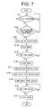
- Fig. 7 is a flow chart showing a control method for the elevator control device 11 in Fig. 3 .
- the elevator control device 11 it is normally checked to see whether a call is registered by the CPU 10 or not (step S11). Then, if a call is registered, it is checked to see whether the destination floor is temporarily registered or not (step S12). If the call is registered and the destination floor is temporarily registered, the car is moved to the called floor (step S13), and the landing doors 2 and car doors (not shown) are opened (step S14).
- step S15 When the previously set time passes after opening the doors (step S15), the landing doors 2 and the car doors are closed (step S16). After this, the destination floor is registered (step S17) and the car is moved to the destination floor (step S18). After the car arrives at the destination floor and is landed, the landing doors 2 and the car doors are opened (step S19). When the time previously set passes after opening the doors (step S20), the landing doors 2 and the car doors are closed (step S21).
- the destination registering apparatus for the elevator since the layout of the destination floor and the route to the guest room are displayed on the hall display device 7 of the same hall operating panel 4 by inputting the room number to the ten-key numerical input device 6 provided at the hall operating panel 4, the display contents are not seen by other users. Also, since the layout and the route are quickly displayed after inputting the room number, there is no fear that the user will forget to look at the display.
- the ten-key numerical input device 6 is connected to the guest room information registering device 12 and it is checked to see whether the input room number is an available number or not, the strangers can be restrained from arbitrarily entering a guest room floor by operating the ten-key numerical input device 6.
- Fig. 8 is a front view showing a hall operating panel of a destination registering apparatus according to a second embodiment of the present invention
- Fig. 9 is a block diagram showing a destination registering apparatus according to the second embodiment.
- a magnetic card recognition device 22 as an input device is used in a hall operating panel 21.
- the magnetic card recognition device 22 is a device for reading magnetic data in magnetic cards (not shown) that users have. Information such as the room number in a hotel or the like is registered in the magnetic card which is also used as a room key.
- the magnetic card recognition device 22 is connected with a magnetic card registering device 23 in which information of the magnetic card corresponding to available room numbers are registered.
- a destination registering apparatus 24 has the destination floor buttons 5, the magnetic card recognition device 22, the hall display device 7, the storage device 8, the selection circuit 9 and the CPU 10.
- the other constructions are the same as in the first embodiment.
- Fig. 10 is a flow chart showing a control method for the destination registering apparatus in Fig. 9 .
- a destination floor button 5 is pushed (step S2) or a magnetic card is inserted into the magnetic card recognition device 22 (step 9). If a magnetic card is inserted into the magnetic card recognition device 22, it is checked to see whether the inserted card is registered in the magnetic card registering device 23 (step 10).
- the other control methods are the same as in the first embodiment.
- the same effect as in the first embodiment can be obtained by using the magnetic card recognition device 22 as the input device. Further, when the ten-key numerical input device 6 is used, anyone can operate it, but since only specified persons have the magnetic card, security can be improved.
- Fig. 11 is a block diagram showing a destination registering apparatus according to a third embodiment of the present invention.
- a car operating panel 31 is provided in a car (not shown). Further, the car operating panel 31 has the same construction as Fig. 2 , and has the destination floor buttons 5, the ten-key numerical input device 6 and a car display device 32.
- a destination registering apparatus 33 according to the third embodiment has the destination floor buttons 5, the ten-key numerical input device 6, the car display device 32, the storage device 8, the selection circuit 9 and the CPU 10.
- the other constructions are the same as in the first embodiment.
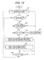
- Fig. 12 is a flow chart showing a control method for the destination registering apparatus 33 in Fig. 11 .
- display contents such as input waiting messages such as "please enter a registration" or the like, or information on events in a building, are displayed on the car display device 32 (step S31).
- step S32 it is normally checked to see whether a destination floor button 5 is pushed or not (stepS32), or whether a room number is input to the ten-key numerical input device 6 (step S33). If no input is received from either the destination floor buttons 5 or the ten-key numerical input device 6, the standby mode display continues.
- step S34 the input floor is registered in the elevator control device 11 as the destination floor, and the layout of the input floor is displayed on the car display device 32 (step S34).
- the display of the layout is performed only for a time previously set in a timer circuit in the selection circuit 9 (step S35), and the display in the car display device 32 reverts back to the contents for standby mode after the set time passed.
- step S36 if a room number is input to the ten-key numerical input device 6, it is checked to see whether the input room number is registered in the guest room information registering device 12 or not (step S36). In the case of no registration, the guest room of the input number is judged not to be available, an error message is displayed on the car display device 32 (step S37). Then, the call registration is refused, and the display reverts back to the standby state.
- the floor including the input room number is registered in the elevator control device 11 as the destination floor, and the layout of the corresponding floor and the route to the guest room that is the destination point are displayed on the car display device 32 (step S38).
- the display of the layout and route is performed only for a time previously set (step S35), and the display in the car display device 32 reverts back to the contents for standby mode after the set time passes.
- the registration of the destination floor in the elevator control device 11 is performed after the car reaches the floor where the call registration is input
- the registration of the destination floor is performed just after inputting because the call registration is input after the user gets on the car.
- the layout of the destination floor and the route to the destination point can be preferentially displayed to the user who has input the guest room number.
- Fig. 13 is a block diagram showing a destination registering apparatus according to a fourth embodiment of the present invention.
- the magnetic card recognition device 22 as an input device is used in a car operating panel 34.
- the magnetic card recognition device 22 is connected with the magnetic card registering device 23.
- a destination registering apparatus 35 has the destination floor buttons 5, the magnetic card recognition device 22, the car display device 32, the storage device 8, the selection circuit 9 and the CPU 10.
- the other constructions are the same as in the first embodiment.
- Fig. 14 is a flow chart showing a control method for the destination registering apparatus 35 in Fig. 13 .
- it is normally checked to see whether a destination floor button 5 is pushed (step S32) or whether the magnetic card is inserted into the magnetic card recognition device 22 (step S39). Then, when the magnetic card is inserted into the magnetic card recognition device 22, it is checked to see whether the input card is registered in the magnetic card registering device 23 (step S40).
- the other control methods are the same as in the third embodiment.
- the same effect as in the third embodiment can be obtained by using the magnetic card recognition device 22 as the input device. Further, security can be further improved as compared with the case using the ten-key numerical input device 6.
- Fig. 15 is a block diagram showing an essential part of a destination registering apparatus according to a fifth embodiment of the present invention.
- a car display device 41 is provided on a car wall 40.
- the elevator control device 11 is provided with a floor information storage device 42 in which the layout of each floor is stored, and a floor information selection device 43 by which required information is selected from the floor information storage device 42 and displayed on the car display device 41.
- the destination registering apparatus further has the car display device 41, the floor information storage device 42 and the floor information selection device 43 in addition to the construction of the first or second embodiment.
- Fig. 16 is a flow chart showing a control method for the elevator control device in Fig. 15 .
- Basic control methods are the same as in the first embodiment ( Fig. 8 ).
- step S22 when the car is moved to the destination floor, it is checked to see whether the next stop floor is registered in the floor information storage device 42 (step S22). If not registered, the flow is the same as in the first embodiment.
- the layout of the next stop floor is displayed on the car display device 41 (step S23). At this time, the route to the destination point as displayed on the hall display device 7 is not displayed.
- the layout display of the car display device 41 is shut off after landing of the car and opening of the doors (step S25). The subsequent control is the same as in the first embodiment.
- the user since the layout of the destination floor is also displayed on the car display device 41 in addition to the display on the hall display device 7, the user can reconfirm, in his or her head, the route to the destination point confirmed at the elevator hall. Further, since the route is not displayed on the car display device 41, there is no fear that the destination point can be seen by other passengers.
- the input device is not limited to the ten-key numerical input device and the magnetic card recognition device, and various types of input devices can be used.
- the present invention is also applicable to elevators installed in other buildings such as, for example, apartments or department stores.
Landscapes
- Engineering & Computer Science (AREA)
- Automation & Control Theory (AREA)
- Computer Networks & Wireless Communication (AREA)
- Mechanical Engineering (AREA)
- Elevator Control (AREA)
- Indicating And Signalling Devices For Elevators (AREA)
Claims (9)
- Zielregistriereinrichtung für einen Aufzug, mit:einer Eingabeeinrichtung (6, 22) zur Eingabe von Informationen, die einen Zielpunkt anweisen, vorgesehen in einem Aufzugsfoyer;einer Speichereinrichtung (8), die Lageplan-Informationen für jede Etage und Informationen zu Wegen von den Aufzugsfoyers jeder Etage zu jedem Zielpunkt speichert;einer Auswahlschaltung (9) zur Auswahl von Informationen entsprechend der Zielpunkteingabe in die Eingabeeinrichtung (6, 22) aus in der Speichereinrichtung (8) gespeicherten Informationen;einer Foyeranzeigeeinrichtung (7) zur Anzeige von durch die Auswahlschaltung (9) ausgewählten Informationen, vorgesehen im Aufzugsfoyer; undeiner CPU (10) zur Ausgabe von Zielregistriersignalen an eine Aufzugssteuereinrichtung (11) und Ausgabe von Informationsauswahlsignalen zu der Auswahlschaltung (9) gemäß der mittels der Eingabeeinrichtung (6, 22) eingegebenen Informationen,wobei die Eingabeeinrichtung (6, 22) mit einer Registriereinrichtung (12, 23) verbunden ist, in welcher Informationen entsprechend verfügbarer Zielpunkte registriert sind,wobei die Zielregistriereinrichtung ausgebildet ist zu prüfen, ob der Zielpunkt entsprechend der eingegebenen Information in der Registriereinrichtung (12, 23) registriert ist, wenn die Information in die Eingabeeinrichtung (6, 22) eingegeben wird, undwobei die Zielregistriereinrichtung derart ausgebildet ist, dass nur dann, wenn der Zielpunkt registriert worden ist, das Zielregistriersignal von der CPU (10) zur Aufzugssteuereinrichtung (11) ausgegeben wird und das Informationsauswahlsignal von der CPU (10) zur Auswahlschaltung (9) ausgegeben wird.
- Zielregistriereinrichtung für einen Aufzug nach Anspruch 1, der ferner eine in einer Kabine vorgesehene Kabinenanzeigeeinrichtung (32) aufweist,
wobei der Lageplan der Etage des nächsten Halts auf der Kabinenanzeigeeinrichtung (32) angezeigt ist. - Zielregistriereinrichtung für einen Aufzug nach Anspruch 1 oder 2,
wobei ferner Rettungswege für Notfälle von jedem Zielpunkt aus in der Speichereinrichtung (8) gespeichert sind, und die Lagepläne, die Wege und die Rettungswege auf der Foyeranzeigeeinrichtung (7) angezeigt sind. - Zielregistriereinrichtung für einen Aufzug, mit:einer Eingabeeinrichtung (6, 22) zur Eingabe von Informationen, die einen Zielpunkt anweisen, vorgesehen in einer Kabine;einem Kabinenbedienungsfeld (31), das eine Kabinenanzeigeeinrichtung (32) zur Anzeige eines Bilds für den Passagier hat, der die Eingabeeinrichtung (6, 22) bedient hat;einer Speichereinrichtung (8), die Lageplan-Informationen für jede Etage und Informationen zu Wegen von den Aufzugsfoyers jeder Etage zu jedem Zielpunkt speichert;einer Auswahlschaltung (9) zur Auswahl von Informationen entsprechend der Zielpunkteingabe in die Eingabeeinrichtung (6, 22) aus in der Speichereinrichtung (8) gespeicherten Informationen, um die Informationen auf der Kabinenanzeigeeinrichtung (32) anzuzeigen; undeiner CPU (10) zur Ausgabe von Zielregistriersignalen an eine Aufzugssteuereinrichtung (11) und Ausgabe von Informationsauswahlsignalen zu der Auswahlschaltung (9) gemäß der mittels der Eingabeeinrichtung (6, 22) eingegebenen Informationen,wobei die Eingabeeinrichtung (6, 22) mit einer Registriereinrichtung (12, 23) verbunden ist, in welcher Informationen entsprechend verfügbarer Zielpunkte registriert sind,wobei die Zielregistriereinrichtung ausgebildet ist zu prüfen, ob der Zielpunkt entsprechend der eingegebenen Information in der Registriereinrichtung (12, 23) registriert ist, wenn die Information in die Eingabeeinrichtung (6, 22) eingegeben ist, undwobei die Zielregistriereinrichtung derart ausgebildet ist, dass nur dann, wenn der Zielpunkt registriert worden ist, das Zielregistriersignal von der CPU (10) zur Aufzugssteuereinrichtung (11) ausgegeben wird und das Informationsauswahlsignal von der CPU (10) zur Auswahlschaltung (9) ausgegeben wird.
- Zielregistriereinrichtung für einen Aufzug nach Anspruch 4,
wobei ferner die Rettungswege für Notfälle von jedem Zielpunkt aus in der Speichereinrichtung (8) gespeichert sind, und die Lagepläne, die Wege und die Rettungswege auf der Foyeranzeigeeinrichtung (7) angezeigt werden. - Zielregistriereinrichtung für einen Aufzug nach einem der Ansprüche 1 bis 5,
wobei die Eingabeeinrichtung (6, 22) eine numerische Eingabeeinrichtung (6) mit Zehnertastatur ist. - Zielregistriereinrichtung für einen Aufzug nach einem der Ansprüche 1 bis 6,
wobei die Eingabeeinrichtung (6, 22) eine Magnetkarten-Erkennungseinrichtung (22) ist. - Zielregistriereinrichtung für einen Aufzug nach einem der Ansprüche 1 bis 7,
wobei die Zielregistriereinrichtung derart ausgebildet ist, dass die Anzeige für den Fall, dass der Zielpunkt nicht in der Registriereinrichtung registriert ist, in den Bereitschaftszustand zurückkehrt, nachdem auf der Anzeigeeinrichtung eine Fehlermeldung angezeigt wurde. - Zielregistriereinrichtung für einen Aufzug nach einem der Ansprüche 1 bis 8,
wobei die Zielregistriereinrichtung derart ausgebildet ist, dass die Rufregistrierung für den Fall, dass der Zielpunkt nicht in der Registriereinrichtung registriert ist, abgelehnt wird.
Applications Claiming Priority (1)
| Application Number | Priority Date | Filing Date | Title |
|---|---|---|---|
| PCT/JP2000/004058 WO2001098191A1 (en) | 2000-06-21 | 2000-06-21 | Destination registering device for elevator |
Publications (3)
| Publication Number | Publication Date |
|---|---|
| EP1293465A1 EP1293465A1 (de) | 2003-03-19 |
| EP1293465A4 EP1293465A4 (de) | 2008-07-30 |
| EP1293465B1 true EP1293465B1 (de) | 2010-03-10 |
Family
ID=11736168
Family Applications (1)
| Application Number | Title | Priority Date | Filing Date |
|---|---|---|---|
| EP00940781A Expired - Lifetime EP1293465B1 (de) | 2000-06-21 | 2000-06-21 | Zielregistriereinrichtung für aufzug |
Country Status (6)
| Country | Link |
|---|---|
| US (1) | US6508334B1 (de) |
| EP (1) | EP1293465B1 (de) |
| JP (1) | JP4754765B2 (de) |
| CN (1) | CN1178840C (de) |
| TW (1) | TW490431B (de) |
| WO (1) | WO2001098191A1 (de) |
Families Citing this family (18)
| Publication number | Priority date | Publication date | Assignee | Title |
|---|---|---|---|---|
| CN1173874C (zh) * | 2000-06-23 | 2004-11-03 | 三菱电机株式会社 | 电梯的显示操作装置 |
| MY137800A (en) * | 2001-12-19 | 2009-03-31 | Inventio Ag | Control panel and method for using a control panel in an elevator |
| JP4434572B2 (ja) * | 2002-11-29 | 2010-03-17 | 東芝エレベータ株式会社 | エレベータ操作盤 |
| DE502004008998D1 (de) * | 2003-06-04 | 2009-04-02 | Inventio Ag | Tableau für Aufzüge mit Schlüsselschalter |
| US7040458B2 (en) * | 2003-06-27 | 2006-05-09 | Fujitec America, Inc. | Elevator destination protocol control with flexible user interface |
| AU2003259775A1 (en) * | 2003-08-11 | 2005-03-10 | Otis Elevator Company | Correlating elevators destination floors with elevators serving those floors by means of color |
| FI117009B (fi) * | 2005-03-08 | 2006-05-15 | Kone Corp | Opastusjärjestelmä |
| US8403113B2 (en) * | 2008-07-02 | 2013-03-26 | Mitsubishi Electric Corporation | Destination floor indication device of elevator |
| US20110115907A1 (en) * | 2009-09-29 | 2011-05-19 | Rory Glenn Cameron | Safe visions |
| JP2015117115A (ja) * | 2013-12-19 | 2015-06-25 | 三菱電機株式会社 | エレベータの情報表示システム |
| KR101703396B1 (ko) * | 2014-12-09 | 2017-02-07 | 연세대학교 원주산학협력단 | 숙박시설 승강기 호출 장치 및 호출 방법 |
| WO2016194231A1 (ja) * | 2015-06-05 | 2016-12-08 | 三菱電機株式会社 | エレベータ情報提示システム |
| US10011460B2 (en) * | 2016-09-27 | 2018-07-03 | Otis Elevator Company | Elevator dynamic displays for messaging and communication |
| US20180099839A1 (en) * | 2016-10-07 | 2018-04-12 | Otis Elevator Company | Elevator call system with mobile device |
| US20180162690A1 (en) * | 2016-12-13 | 2018-06-14 | Otis Elevator Company | Information preview for elevator passengers |
| WO2019102592A1 (ja) * | 2017-11-24 | 2019-05-31 | 三菱電機株式会社 | エレベーター用表示装置およびエレベーター用表示装置の表示制御方法 |
| WO2021214189A1 (de) * | 2020-04-23 | 2021-10-28 | Inventio Ag | Aufzugsbedieneinrichtung mit zwei passagierseitig getrennt angeordneten rufeingabeeinrichtungen |
| CN112348710A (zh) * | 2020-10-22 | 2021-02-09 | 深圳优地科技有限公司 | 酒店入住管理方法、装置、移动机器人及存储介质 |
Family Cites Families (13)
| Publication number | Priority date | Publication date | Assignee | Title |
|---|---|---|---|---|
| JPS6212589A (ja) * | 1986-07-10 | 1987-01-21 | 三菱電機株式会社 | エレベ−タの案内装置 |
| JPH0633140B2 (ja) * | 1987-01-23 | 1994-05-02 | 株式会社日立製作所 | 行き先案内システム |
| JPH02123081A (ja) * | 1988-10-31 | 1990-05-10 | Mitsubishi Electric Corp | エレベータの操作装置 |
| JPH0664856A (ja) * | 1992-08-10 | 1994-03-08 | Hitachi Ltd | エレベーターにおける案内表示装置 |
| JPH06212589A (ja) | 1993-01-18 | 1994-08-02 | Iwashina Seisakusho:Kk | 高濃度タワーの紙料取出構造 |
| JPH06321445A (ja) * | 1993-05-10 | 1994-11-22 | Toshiba Corp | エレベータ |
| JPH07187533A (ja) * | 1993-12-27 | 1995-07-25 | Toshiba Corp | エレベーター装置 |
| US5551533A (en) * | 1994-04-01 | 1996-09-03 | Otis Elevator Company | Audio direction and information for elevator passengers |
| JPH09118484A (ja) * | 1995-10-26 | 1997-05-06 | Toshiba Corp | 自走式エレベーターのホール呼び登録装置 |
| JPH10194618A (ja) * | 1997-01-16 | 1998-07-28 | Mitsubishi Denki Bill Techno Service Kk | エレベーターの乗場呼登録装置 |
| ATE232502T1 (de) * | 1997-03-04 | 2003-02-15 | Inventio Ag | Auf den stockwerken angeordnete rufregistrier- und anzeigeeinrichtungen für aufzüge |
| ZA200001299B (en) * | 1999-04-01 | 2000-10-20 | Inventio Ag | Method of communication with a transportation system. |
| US6341668B1 (en) * | 2000-04-03 | 2002-01-29 | Televator One, Llc | Interactive elevator communication system |
-
2000
- 2000-06-21 EP EP00940781A patent/EP1293465B1/de not_active Expired - Lifetime
- 2000-06-21 US US09/979,152 patent/US6508334B1/en not_active Expired - Fee Related
- 2000-06-21 JP JP2002503638A patent/JP4754765B2/ja not_active Expired - Fee Related
- 2000-06-21 CN CNB008118574A patent/CN1178840C/zh not_active Expired - Fee Related
- 2000-06-21 WO PCT/JP2000/004058 patent/WO2001098191A1/ja not_active Ceased
- 2000-06-22 TW TW089112259A patent/TW490431B/zh not_active IP Right Cessation
Also Published As
| Publication number | Publication date |
|---|---|
| EP1293465A4 (de) | 2008-07-30 |
| CN1178840C (zh) | 2004-12-08 |
| US6508334B1 (en) | 2003-01-21 |
| EP1293465A1 (de) | 2003-03-19 |
| JP4754765B2 (ja) | 2011-08-24 |
| CN1370128A (zh) | 2002-09-18 |
| TW490431B (en) | 2002-06-11 |
| WO2001098191A1 (en) | 2001-12-27 |
Similar Documents
| Publication | Publication Date | Title |
|---|---|---|
| EP1293465B1 (de) | Zielregistriereinrichtung für aufzug | |
| US6315083B1 (en) | Transportation system control with user input of travel destination designations | |
| JPWO2001098191A1 (ja) | エレベータの行先登録装置 | |
| EP2565141A2 (de) | Aufzugssteuereinrichtung | |
| JP2002370877A (ja) | 来訪者報知装置 | |
| JP7021681B2 (ja) | 呼び登録装置、呼び登録装置の制御方法および制御プログラム | |
| JPH1160084A (ja) | エレベーターの運転装置 | |
| JPH02127377A (ja) | エレベーターの呼び登録装置 | |
| JPH11146391A (ja) | エレベータのための情報システム | |
| JP2003104633A (ja) | エレベータ呼び登録装置 | |
| JPH01242379A (ja) | エレベータ案内操作盤 | |
| JPH11146392A (ja) | エレベータのための情報システム | |
| JP2005231885A (ja) | エレベーターの呼び登録装置 | |
| JP2779089B2 (ja) | エレベータ用情報表示装置 | |
| JP2005096945A (ja) | エレベータのセキュリティシステム | |
| JP7156473B1 (ja) | エレベータの群管理システム | |
| JPH05155541A (ja) | エレベータ管理方法 | |
| JP2878812B2 (ja) | エレベータの表示装置 | |
| JP2024139856A (ja) | エレベータシステム | |
| JPH0383774A (ja) | エレベータの遠隔制御装置 | |
| JP2008293467A (ja) | レジャーホテル用マルチ情報装置及びこれを用いた対面防止システム及び案内システム並びに予約システム | |
| JPS60242188A (ja) | エレベ−タ−の呼び登録装置 | |
| JP2005119847A (ja) | エレベータの制御装置 | |
| JPH0157040B2 (de) | ||
| JP2000177938A (ja) | エレベータ制御装置 |
Legal Events
| Date | Code | Title | Description |
|---|---|---|---|
| PUAI | Public reference made under article 153(3) epc to a published international application that has entered the european phase |
Free format text: ORIGINAL CODE: 0009012 |
|
| 17P | Request for examination filed |
Effective date: 20020321 |
|
| AK | Designated contracting states |
Kind code of ref document: A1 Designated state(s): AT BE CH CY DE DK ES FI FR GB GR IE IT LI LU MC NL PT SE Designated state(s): AT BE CH CY DE DK ES FI FR GB GR IE IT LI LU MC NL PT SE |
|
| RBV | Designated contracting states (corrected) |
Designated state(s): AT NL |
|
| REG | Reference to a national code |
Ref country code: DE Ref legal event code: 8566 |
|
| RAP1 | Party data changed (applicant data changed or rights of an application transferred) |
Owner name: MITSUBISHI DENKI KABUSHIKI KAISHA |
|
| A4 | Supplementary search report drawn up and despatched |
Effective date: 20080701 |
|
| 17Q | First examination report despatched |
Effective date: 20081006 |
|
| GRAP | Despatch of communication of intention to grant a patent |
Free format text: ORIGINAL CODE: EPIDOSNIGR1 |
|
| GRAS | Grant fee paid |
Free format text: ORIGINAL CODE: EPIDOSNIGR3 |
|
| GRAA | (expected) grant |
Free format text: ORIGINAL CODE: 0009210 |
|
| AK | Designated contracting states |
Kind code of ref document: B1 Designated state(s): NL |
|
| REG | Reference to a national code |
Ref country code: NL Ref legal event code: T3 |
|
| PLBE | No opposition filed within time limit |
Free format text: ORIGINAL CODE: 0009261 |
|
| STAA | Information on the status of an ep patent application or granted ep patent |
Free format text: STATUS: NO OPPOSITION FILED WITHIN TIME LIMIT |
|
| 26N | No opposition filed |
Effective date: 20101213 |
|
| PGFP | Annual fee paid to national office [announced via postgrant information from national office to epo] |
Ref country code: NL Payment date: 20110629 Year of fee payment: 12 |
|
| REG | Reference to a national code |
Ref country code: NL Ref legal event code: V1 Effective date: 20130101 |
|
| PG25 | Lapsed in a contracting state [announced via postgrant information from national office to epo] |
Ref country code: NL Free format text: LAPSE BECAUSE OF NON-PAYMENT OF DUE FEES Effective date: 20130101 |