EP1293604A2 - Système de voie autostabilisant - Google Patents
Système de voie autostabilisant Download PDFInfo
- Publication number
- EP1293604A2 EP1293604A2 EP02255566A EP02255566A EP1293604A2 EP 1293604 A2 EP1293604 A2 EP 1293604A2 EP 02255566 A EP02255566 A EP 02255566A EP 02255566 A EP02255566 A EP 02255566A EP 1293604 A2 EP1293604 A2 EP 1293604A2
- Authority
- EP
- European Patent Office
- Prior art keywords
- ballast
- gabions
- track structure
- ballast bed
- bed
- Prior art date
- Legal status (The legal status is an assumption and is not a legal conclusion. Google has not performed a legal analysis and makes no representation as to the accuracy of the status listed.)
- Withdrawn
Links
Images


Classifications
-
- E—FIXED CONSTRUCTIONS
- E01—CONSTRUCTION OF ROADS, RAILWAYS, OR BRIDGES
- E01B—PERMANENT WAY; PERMANENT-WAY TOOLS; MACHINES FOR MAKING RAILWAYS OF ALL KINDS
- E01B1/00—Ballastway; Other means for supporting the sleepers or the track; Drainage of the ballastway
- E01B1/001—Track with ballast
Definitions
- the invention relates to a railway track structure formed of at least a pair of rails, which are fastened to sleepers via which they are supported on a bed of ballast material.
- This invention also relates to a method of making track structures and a new ballast bed for such track structures.
- transport capacity of existing or newly laid railway tracks is often required to be increased, which can be realized with heavier and more frequent trains per day that generally attain higher speeds.
- This increase in transport capacity leads to higher and heavier loads being applied to the railway track in its entirety and to its individual components, an important role being played by the dynamic load of the trains that ply on the rails.
- ballast bed material On railway track sections, which frequently carry bulk material, or in deserts and other loose soil dry areas the ballast bed material, becomes fouled up with this bulk material or sand, which also detracts from the proper functioning of the ballast bed.
- the invention has for its object to provide an improved railway track, which does not have the limitations of the prior art railway tracks and no longer has the afore-mentioned disadvantages.
- track structure for fastening rails comprising:-
- the elements of the ballast bed are defined by support box type elements in which ballast material such as pebbles and broken stones is filled.
- the support elements are in the form of wire boxes or in the form of a box having perforated walls.
- the walls of the support element are tensioned and the ballast material filled in the support elements include resiliently compressible elements such as rubber tyre crumbs.
- the resilient pad is provided between the sleeper and the ballast bed is an elastomeric sheet element reinforced on the inside or the outside, preferably provided on the surface of the gabions forming the ballast bed or within the gabions forming the ballast bed.
- the support element for the gabions forming the ballast bed has a wall which constitutes the resilient element.
- the invention also discloses a method of making a track structure consisting the steps of:-
- ballast bed for the track structure consisting of inter fitting gabions formed by filling support elements with ballast material at least some of the gabions provided with resilient elements for mounting sleepers thereon.
- the ballast bed has ballast material, which includes crumbs of resilient material, and the support elements are in the nature of a wire box and the resilient element is a wall of the support element.
- the resilient element is provided either outside or inside the gabion.
- the railway track structure is characterized in that beneath the sleepers the ballast is confined in wire boxes known as gabions.
- the ballast is provided in one or more supporting elements in which the ballast material is filled.
- it relates to a device for securing railway rails on a ballast track or a solid track in a highly resilient manner.
- Ballast tracks which are fitted with the standard superstructure also frequently, exhibit rail compression values that are too low for use in high-speed transport on new routes.
- the resilience of ballast permits track compression which results in a rail head depression of about 0.6 mm. This track compression is clearly below today's desired rail head depression of 1.5 mm.
- This invention envisages the use of at least one resilient layer between the sleeper and the ballast track in order that the track system is self stabilizing.
- a resilient intermediate pad is disposed between the rail sleeper and the ballast bed; this pad ensures sufficient compression.
- the resilient intermediate pad is reinforced therewithin or on the outside.
- the present invention is based on the object of using standard elements and standard sleepers to design a rail attachment, by means of which high rail compression values and proper self stabilization can be achieved.
- the device for securing railway rails on a ballast track or a solid track includes a standard sleeper used on the ballast track; consisting of a plurality of gabions holding ballast and a resilient pad placed below the sleeper typically below the rail seat between the sleeper and the gabions.
- the resilient intermediate pad and/or the gabions may have a larger extension in the sleeper's longitudinal direction than the rail flange and therefore protrude across the width of the rail flange on both sides. As a result, the pressure is distributed over a larger surface area of the ballast bed via the resilient intermediate pad.
- the resilient pad may be secure with the gabion elements such that the upper wall surface may be flexible/resilient.
- the rubber resilient pad may be independent of the gabions.
- the gabions being typically of elements made of wire net or fabric.
- the resistance of the ballast bed to dynamic load and deformation will be favourably influenced if according to the invention the gabions filled with ballast material are under tension. This tension ensures that the ballast material in the gabion will hold together.
- the ballast material may be made up of various grades of pebble, crushed stone, pebble-sand mixtures or some other material of sufficient strength. To stabilize elasticity elastic components may be added to the ballast material.
- the resilient pad may be a bladder of a synthetic polymeric material, which may be placed in the gabion near the closure and inflated with compressed air after tying up the gabion.
- a bladder of a synthetic polymeric material which may be placed in the gabion near the closure and inflated with compressed air after tying up the gabion.
- waste products that are sufficiently elastic.
- a simple embodiment of the railway track structure according to the invention is characterized in that beneath each sleeper there are positioned at least two gabions filled with ballast material.
- the gabions are advantageously so positioned beneath the sleepers that halfway between the two rails the two facing ends of the gabions are spaced at some distance apart. Said space is filled with ballast material or the like.
- a particularly effective embodiment according to the invention is characterized in that the sleepers are each positioned within the upper part of a gabion. This provision has the advantage that the gabions need not be fastened to the sleepers.
- the gabions may be filled with some hard ballast material such as pebbles, broken stone, sand and/or slag. Favourable results are also expected if according to the invention the gabions are filled with a mixture of hard ballast material, such as pebbles, broken stone and/or sand, and elastic material, such as pieces of elastomeric material typically waste tyre crumb.
- a favourable embodiment of the railway track structure according to the invention is characterized in that measured over their side resting on the subsoil, the filled gabions extending in longitudinal direction of the sleepers have varying lengths and varying transverse dimensions in longitudinal direction of the rails.
- ballast gabions will not require any maintenance for many years as far as the ballast bed is concerned.
- the gabions are porous and air and water will have access to the contents of the gabions.
- the filled gabions have a greater width than the sleepers, as a result of which the ballast bed will have a high load bearing capacity and the load is uniformly distributed.
- the ballast bed according to the invention is also expected to be of satisfactory use in desert-like regions with blowing sand.
- a conventional ballast bed is made impermeable to water by all the sand and loses its elasticity in that fine sand particles will deposit in the ballast bed.
- the invention also comprises a method of building a railway track structure by which a bed of ballast material with sleepers and rails is provided, which is characterized according to the invention in that beneath the sleepers there are placed one or more gabions or like containers filled with ballast material.
- the gabions may with advantage be fastened to the sleepers.
- a favourable embodiment of the method according to the invention is characterized in that in the gabion filled with ballast material this material is set into vibration in order that it may be compacted before the gabion is closed. It is preferred that the ballast material is set into vibration at a frequency and at an amplitude such that the ballast material behaves practically like a liquid, and the gabion is closed while the ballast material in it is in vibratory motion or afterwards. In that way the filling of the gabions with ballast material will be optimal, with the wire net or fabric material of the filled gabions being tensioned.
- a favourable embodiment of the method according to the invention is characterized in that the gabion, after it has successively been filled with ballast material and closed, is so compressed by pre-tension transverse to its longitudinal direction that two opposed flattened faces are formed.
- the gabions placed on their supports may be covered with ballast material.
- at least one compressible resilient pad is positioned between the sleeper and the ballast gabions.
- Laying a railway track according to the invention may be simplified by prefabricating a group of sleepers, say 4-6, with gabions filled with ballast material fastened to them and collectively fastening the whole construction to a carrier, such as a mounting rail, after which the carrier with sleepers and gabions is transported to the site for laying the railway track.
- the invention also comprises a gabion-shaped body formed by a flexible container filled with ballast material, which body is formed in the manner described hereinbefore for use in the railway track according to the invention.
- the invention also comprises a foundation for a railway, a building structure, a machine, a road or some other construction, which is characterized in that said foundation contains a plurality of the afore-described gabion-shaped bodies according to the invention.
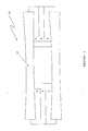
- a self-stabilizing railway track system in accordance with this invention is generally indicated by the reference numeral 10.
- FIGS. 1-3 illustrate the track of which the sleepers are referred to by reference numeral 12 having rail seats at either end.
- the gabions are referred to by the numerals 1, 2, 4 and 5.
- the sleepers are spaced at about 65 cm centres apart.
- each sleeper 12 Beneath each sleeper 12 are the gabions 1,2,4 and 5 filled with ballast material such as coarse gravel or rubble. Each sleeper 12 may be fastened to the gabions 4 and 5. Fastening to the gabions 4 and 5 may be effected with the aid of optionally re-adjustable clamp couplings [not shown].
- the rails are fastened to the sleepers 12 in a conventional manner, which is not shown.
- the gabions which succeed each other in longitudinal direction of the rails, touch on their sides at the points. Alternatively, however, some small space may be left between the sides of the gabions. As the two facing ends of the gabions 4,5 beneath each sleeper do not touch, some free space 3 is left in the centre of the track, halfway between the two rails.
- the subsoil supporting the gabions may be of the same kind as that of the ballast bed of a conventional railway track.
- a resilient layer 14 is provided between the sleeper 12 and the gabion arrangement.
- the gabions are typically of a wire netting having a high tenacity.
- FIGs. 4 5 6 and 7 are schematic illustrations of embodiments of gabions 1 and 2 and 4 and 5 respectively according to the invention in which the sleepers 12 are each positioned on gabions filled with ballast material.
- Typical shape and relative dimensions of the gabions are provided in the drawings, which are merely illustrative of the sizes of the gabions and are in no way limiting or restrictive in nature.
- a typical gabion construction is seen in Figure 7 in which a support wall 16 of the gabion is seen in the form of a mesh and the gabion support element contains ballast material 18 in the form of pebbles or stones.
- To prevent damage to the gabions protective material may be provided on the upperside of the sleepers both on the inside and the outside of the gabions.
- the highly resilient intermediate pad 14 typically made of reinforced rubber allows the rail to exhibit the necessary vertical depression and can be selected such that the rail's desired compression is achieved.
- the pad evenly distributes over a large surface area those vertical forces, which act upon the rail.
- the described rail attachment is also suitable for the use of high-speed trains on new routes. It is therefore possible to convert an existing ballast track to the securing system according to the invention by continuing to use standard sleepers, which also makes this system suitable for use in high speed transport because of their self stabilizing properties.
- ballast track It is also possible to fill up the cavities of the ballast track with concrete, asphalt of the like and therefore to continue using this securing system on a solid track without changing the system because the manner of securing rails according to the invention achieves the desired high compression values as regards overall resilience even without the ballast foundation's contribution.
- the resilient pad can be provided within the gabions forming the ballast bed.
- the support element for the gabions forming the ballast bed can have a wall, which constitutes the resilient pad.
- the present invention also encompasses a method of making a track structure as hereinabove defined, consisting the steps of:-
- the present invention further encompasses a ballast bed for the track structure as hereinabove defined consisting of inter fitting gabions formed by filling support elements with ballast material at least some of the gabions provided with resilient pads for mounting sleepers thereon.
- the ballast material includes crumbs of resilient material.
- the support elements are in the nature of a wire box.
- the resilient pad is a wall of the support element, or alternatively, the resilient pad is provided either outside or inside the gabion.
- the present invention encompasses a gabion as herein described for a ballast bed as hereinabove defined.
Landscapes
- Engineering & Computer Science (AREA)
- Architecture (AREA)
- Civil Engineering (AREA)
- Structural Engineering (AREA)
- Machines For Laying And Maintaining Railways (AREA)
- Railway Tracks (AREA)
Applications Claiming Priority (2)
| Application Number | Priority Date | Filing Date | Title |
|---|---|---|---|
| IN900MU2001 | 2001-09-18 | ||
| INMU09002001 | 2001-09-18 |
Publications (2)
| Publication Number | Publication Date |
|---|---|
| EP1293604A2 true EP1293604A2 (fr) | 2003-03-19 |
| EP1293604A3 EP1293604A3 (fr) | 2004-04-14 |
Family
ID=11097293
Family Applications (1)
| Application Number | Title | Priority Date | Filing Date |
|---|---|---|---|
| EP02255566A Withdrawn EP1293604A3 (fr) | 2001-09-18 | 2002-08-08 | Système de voie autostabilisant |
Country Status (2)
| Country | Link |
|---|---|
| US (1) | US6672515B2 (fr) |
| EP (1) | EP1293604A3 (fr) |
Cited By (1)
| Publication number | Priority date | Publication date | Assignee | Title |
|---|---|---|---|---|
| EP2154290A4 (fr) * | 2007-04-27 | 2013-12-11 | Tokai Ryokaku Tetsudo Kk | Ouvrage d'arrêt de ballast, voie encaissée |
Families Citing this family (3)
| Publication number | Priority date | Publication date | Assignee | Title |
|---|---|---|---|---|
| DE102005054820A1 (de) * | 2005-11-15 | 2007-05-24 | Rail.One Gmbh | Feste Fahrbahn für Schienenfahrzeuge |
| US9515538B2 (en) * | 2008-05-29 | 2016-12-06 | Nidec Motor Corporation | Dynamoelectric machine assemblies having memory for use by external devices |
| JP5379422B2 (ja) * | 2008-08-05 | 2013-12-25 | 東海旅客鉄道株式会社 | バラスト止め工、有道床軌道 |
Family Cites Families (6)
| Publication number | Priority date | Publication date | Assignee | Title |
|---|---|---|---|---|
| DE1914712C3 (de) * | 1969-03-22 | 1973-09-27 | Stahlwerke Peine-Salzgitter Ag, 3150 Peine | Verfahren zum Herstellen eines Eisen bahngleises |
| US3756507A (en) * | 1970-08-06 | 1973-09-04 | Salzgitter Peine Stahlwerke | Railroad track bed |
| US3841554A (en) * | 1972-05-03 | 1974-10-15 | Phillips Petroleum Co | Stabilized railway bed and method of construction |
| EP0105560B1 (fr) * | 1982-10-06 | 1986-04-23 | Akzo N.V. | Structure de voie de chemin de fer et méthode de construction d'une telle structure |
| GB8725290D0 (en) * | 1987-10-28 | 1987-12-02 | Waters J M | Track support system |
| ATE196333T1 (de) * | 1995-05-11 | 2000-09-15 | Pfleiderer Infrastrukturt Gmbh | Massnahmen zur luftschallverminderung bei schienenverkehrswegen, vornehmlich bei festen fahrbahnen für schienengebundenen verkehr und verfahren zur durchführung der massnahmen |
-
2002
- 2002-07-26 US US10/206,024 patent/US6672515B2/en not_active Expired - Fee Related
- 2002-08-08 EP EP02255566A patent/EP1293604A3/fr not_active Withdrawn
Cited By (2)
| Publication number | Priority date | Publication date | Assignee | Title |
|---|---|---|---|---|
| EP2154290A4 (fr) * | 2007-04-27 | 2013-12-11 | Tokai Ryokaku Tetsudo Kk | Ouvrage d'arrêt de ballast, voie encaissée |
| EP3098348A1 (fr) * | 2007-04-27 | 2016-11-30 | Central Japan Railway Company | Structure de retenue de ballast |
Also Published As
| Publication number | Publication date |
|---|---|
| US6672515B2 (en) | 2004-01-06 |
| EP1293604A3 (fr) | 2004-04-14 |
| US20030052182A1 (en) | 2003-03-20 |
Similar Documents
| Publication | Publication Date | Title |
|---|---|---|
| KR101421007B1 (ko) | 궤도용 레일 매립형 프리캐스트 콘크리트 슬래브 패널 | |
| US8240580B2 (en) | Ballast retaining structure, bedded track | |
| US4679731A (en) | Railway track structure and a method of building such structure and bags filled with ballast material | |
| US6502760B2 (en) | Rail support | |
| KR20160009030A (ko) | 콘크리트 침목 및 고형 차로 | |
| US2719676A (en) | Road bed and track for railroads | |
| US6672515B2 (en) | Self stabilizing track system | |
| JP3432302B2 (ja) | 線路軌道の築造方法および改修方法 | |
| JP2014125736A (ja) | まくら木 | |
| CN1011248B (zh) | 铁道上部结构的施工方法 | |
| WO2004079094A2 (fr) | Structure support de genie civil | |
| RU2043455C1 (ru) | Способ строительства дорожного полотна | |
| TWI445869B (zh) | 附接至梯形枕木之鐵軌 | |
| JP3046735B2 (ja) | 吸音効果を持たせた省力型軌道構造 | |
| EP0742318B1 (fr) | Mesures pour la réduction du bruit aérien en trafic ferroviaire particulièrement en voies sans ballast pour trafic roulant sur rails et procédé de l'exécution des mesures | |
| JP3829044B2 (ja) | 鉄道マクラギの支持力補強構造及び支持力補強方法 | |
| KR100709570B1 (ko) | 습지 침수지역 철도 레일 궤도 설치구조 | |
| JP2002081002A (ja) | バラスト軌道 | |
| CN104805738B (zh) | 有砟铁路道床的加固装置、系统及方法 | |
| JP2622492B2 (ja) | 吸音効果を持たせた省力型軌道構造 | |
| US341575A (en) | Road-bed or rail-support for railways | |
| KR100642345B1 (ko) | 연약지반 침하방지를 위한 충격흡수형 철로 | |
| BE1017167A3 (nl) | Spoorweg voor absorptie van geluiden van spoorvoertuigen. | |
| Hwang et al. | Performance of the reinforced railroad roadbed of crushed stones under the simulated cyclic loading using multi purpose loading system | |
| JPH0313601A (ja) | 噴泥現象のおきるのを阻止する鉄道路盤の構築工法 |
Legal Events
| Date | Code | Title | Description |
|---|---|---|---|
| PUAI | Public reference made under article 153(3) epc to a published international application that has entered the european phase |
Free format text: ORIGINAL CODE: 0009012 |
|
| AK | Designated contracting states |
Kind code of ref document: A2 Designated state(s): AT BE BG CH CY CZ DE DK EE ES FI FR GB GR IE IT LI LU MC NL PT SE SK TR Designated state(s): AT BE BG CH CY CZ DE DK EE ES FI FR GB GR IE IT LI LU MC NL PT SE SK TR |
|
| AX | Request for extension of the european patent |
Extension state: AL LT LV MK RO SI |
|
| PUAL | Search report despatched |
Free format text: ORIGINAL CODE: 0009013 |
|
| AK | Designated contracting states |
Kind code of ref document: A3 Designated state(s): AT BE BG CH CY CZ DE DK EE ES FI FR GB GR IE IT LI LU MC NL PT SE SK TR |
|
| AX | Request for extension of the european patent |
Extension state: AL LT LV MK RO SI |
|
| 17P | Request for examination filed |
Effective date: 20040722 |
|
| AKX | Designation fees paid |
Designated state(s): AT BE BG CH CY CZ DE DK EE ES FI FR GB GR IE IT LI LU MC NL PT SE SK TR |
|
| 17Q | First examination report despatched |
Effective date: 20050907 |
|
| STAA | Information on the status of an ep patent application or granted ep patent |
Free format text: STATUS: THE APPLICATION IS DEEMED TO BE WITHDRAWN |
|
| 18D | Application deemed to be withdrawn |
Effective date: 20070301 |