EP1293621A1 - Vorrichtung zur Verankerung von vorgefertigten Gebäudeteilen - Google Patents
Vorrichtung zur Verankerung von vorgefertigten Gebäudeteilen Download PDFInfo
- Publication number
- EP1293621A1 EP1293621A1 EP01122279A EP01122279A EP1293621A1 EP 1293621 A1 EP1293621 A1 EP 1293621A1 EP 01122279 A EP01122279 A EP 01122279A EP 01122279 A EP01122279 A EP 01122279A EP 1293621 A1 EP1293621 A1 EP 1293621A1
- Authority
- EP
- European Patent Office
- Prior art keywords
- building
- recess
- building structure
- support
- support element
- Prior art date
- Legal status (The legal status is an assumption and is not a legal conclusion. Google has not performed a legal analysis and makes no representation as to the accuracy of the status listed.)
- Granted
Links
- 238000004873 anchoring Methods 0.000 title claims description 10
- 238000005253 cladding Methods 0.000 claims description 6
- 230000002787 reinforcement Effects 0.000 description 2
- 238000010276 construction Methods 0.000 description 1
- 239000000834 fixative Substances 0.000 description 1
- 238000004519 manufacturing process Methods 0.000 description 1
- 239000000463 material Substances 0.000 description 1
- 239000004575 stone Substances 0.000 description 1
Images


Classifications
-
- E—FIXED CONSTRUCTIONS
- E04—BUILDING
- E04F—FINISHING WORK ON BUILDINGS, e.g. STAIRS, FLOORS
- E04F13/00—Coverings or linings, e.g. for walls or ceilings
- E04F13/07—Coverings or linings, e.g. for walls or ceilings composed of covering or lining elements; Sub-structures therefor; Fastening means therefor
- E04F13/08—Coverings or linings, e.g. for walls or ceilings composed of covering or lining elements; Sub-structures therefor; Fastening means therefor composed of a plurality of similar covering or lining elements
- E04F13/0801—Separate fastening elements
- E04F13/0832—Separate fastening elements without load-supporting elongated furring elements between wall and covering elements
- E04F13/0853—Separate fastening elements without load-supporting elongated furring elements between wall and covering elements adjustable perpendicular to the wall
- E04F13/0855—Separate fastening elements without load-supporting elongated furring elements between wall and covering elements adjustable perpendicular to the wall adjustable in several directions, one of which is perpendicular to the wall
Definitions
- the invention relates to a device for anchoring prefabricated building parts, in particular facade panels, on a building structure in the preamble of the claim 1 specified genus.
- a support and anchoring device is known from EP 0 423 660 B1 for those supported by a supporting structure of a building Prefabricated parts of the building known that a socket-like Support includes that with an opening in a building support structure is provided or limited.
- the device has a support element with an elongated cylindrical body, its cross section and length the cross section and the length of the support is adapted. This is removably fitted into the support and one the ends protrude from it.
- the support element is with Support means, which is a support area for one with the building support structure Define part of the building to be connected, and with means for adjusting and varying the horizontal and vertical position of the support means with respect to the support Mistake.
- the adjustment means allow adjustment of the Position of the part of the building that corresponds to the building structure connect is in two directions.
- the recess for the support in the building structure must be provided, must be relatively deep, to ensure secure anchoring. A corresponding However, depth is not always available for the support Available. In addition, there is a corresponding pipe for receiving of the support element in the building structure required, wherein sufficient play for assembly is necessary. fixative are not available.
- the invention is based on the requirement of a device for Anchoring of prefabricated parts of the building of the generic type To create a way that provides secure anchoring and the only one recess with shallow depth in the building structure needed.
- the support element Since the support element is horizontal using the fastening screw Is fixed and in the recess in the Building structure supports only, the recess can be proportionate be made small and need not be of great depth exhibit.
- the support element represents a simple welded construction and is so easy and inexpensive to manufacture. Since you can readjust in the vertical direction, the device is easy to use.
- the legs of the support element are advantageously different long and the long leg is due to the building structure on. It is envisaged that the part of the building on a Contact surface of the support element rests, the support element in particular in a recess in the part of the building protrudes. The support of the support element on which the part of the building rests inclined, the bearing surface in Towards the building structure. This results in a particularly secure fixation of the building part on the support element.
- one arranged on the support element horizontal set screw the horizontal distance between Support element and part of the building is changeable, preferably the screw head inside the recess of the building part on this.
- a vertical adjusting screw arranged on the support element is adjustable, the screw head of the vertical Adjust yourself to the bottom of the recess in the building structure supported.
- the adjustment of the horizontal and vertical distance is particularly easy with the screws realizable. The screws allow a fine adjustment of the Distance with little effort.
- the means for adjusting the position of the building part are expediently arranged in one of the transverse plates of the support element.
- That the recess in the building structure and / or the Recess in the building part is clad.
- the disguise in the recess or in the recess is in particular with Struts anchored in the building part or in the building structure.
- the cladding of the recess and recess provides a simple one and inexpensive way to maintain strength in to increase heavily used areas.
- Fig. 1 shows a device 1 for anchoring prefabricated Building parts 3 on a building structure 4.
- the device 1 has a support element 2, the two L-shaped Includes side parts 5 which at their ends, i.e. on the narrow sides the legs 21 and 22, with transverse plates 6 to a closed Profile are welded.
- the short leg 21 of the Carrying element 2 closes with the long leg 22 An angle that is greater than 90 °.
- the legs 21, 22 can however, also be arranged at right angles to each other and the short leg 21 of the support element is thickened at the end of the leg be so that there is an inclined support surface 7.
- the long leg 22 of the support element 2 is in a recess 16 arranged in a building structure 4 and with a Fixing screw 9 in the horizontal direction in this fixed.
- the cross plate 6 of the long leg 22 is arranged above the bottom 17 of the recess 16. The cross plate 6 is penetrated by the adjusting screw 11, the Head rests on the floor 17 and engages with the nut 18 is.
- the nut 18 is fixed on the support element 2, in particular welded. So can the relative vertical position be adjusted between building structure 4 and support element 2.
- the short leg 21 of the support element 2 protrudes from the recess 16 over the building structure 4 into a recess 8 of a building part 3 anchored to the building structure 4.
- the building part 3 can for example be a facade panel be made of different materials such as Stone or concrete can exist. However, others can Facade elements can be fixed with the device.
- the upper Wall 20 of the recess 8 in the building part 3 is in the direction of the building structure 4 is inclined downwards, the angle of inclination the wall 20 the angle of inclination ⁇ of the contact surface 7 of the support element 2 corresponds.
- the cross plate 6 on the short Leg 21 of the support element 2 is from a screw 10 protrudes, their head on the vertical boundary of the recess 8 abuts and which engages with one on the cross plate 6 welded nut 19 is.
- Using the screw 10 is the horizontal distance between support element 2 and part of the building 3 adjustable. It may be advantageous to adjust the screws 10 and 11 on part 3 of the building or on the building structure 4 to be provided. In another embodiment, can be provided, the adjusting screw 11 also on the short To provide legs 21 of the support member 2 so that the set screw 11 acts on the contact surface 7.
- the fastening screw 9 is as shown in Fig. 2 between the two side parts 5 on the long leg 22 of the Support element 2 arranged. Under the screw head the Screw 9, a plate 23 is arranged over which the horizontal Fastening force from the building structure 4 to the both legs 5 is transmitted. Between the long Leg 22 of the support member 2 and the building structure 4 is a gap 24 is formed. The long leg 22 is supported the arranged at its lower end cross plate 6 on the Building structure 4 onwards. By tilting the support element 2 the angle ⁇ can be set by means of the fastening screw 9 become.
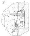
- FIG. 3 shows a further embodiment variant of the device 1 shown.
- the cross plate 6 on the short leg 21 of the supporting element 2 is arranged on the outer longitudinal side of the leg 21, down into the recess 16 in the building structure 4 protrudes.
- the nut 18 is below the cross plate 6 arranged, in which the screw 11 is screwed.
- the Nut 18 is supported on the cross plate 6, so that the vertical distance between building structure 4 and support element 2 can be varied.
- the nut 18 can on the cross plate 6th be welded on to prevent rotation relative to the transverse plate 6 to avoid.
- a covering 14 is arranged in the recess, which is anchored in the building structure with struts 15 is.
- the long leg 22 is on the building structure 4 with a Fastening screw 9 attached.
- the fastening screw 9 is screwed into the building structure 4 in a socket 26, which is anchored in the building structure with a strut 27 is.
- the horizontal screw 10 is in a long leg 22 of the support element 2 arranged socket 29th screwed. Your head is on the wall of the recess 8, whereby the distance between the support element 2 and part of the building 3 can be adjusted in the horizontal direction.
- an end plate 6 is arranged, which forms the bearing surface 7 for the building part 3.
- the long leg 22 protrudes into one formed on the building part 3 Recess 8.
- the recess 8 is like the recess 16 with a cladding 12 provided with struts 13 in the building part is anchored.
- a reinforcement 25 is arranged, a deformation of the panel 12 by too large Contact forces prevented.
- the elements of the device 1 are perspective shown.
- the strut 13 is arranged, with which the panel 12 in a building part 3 can be anchored.
- a reinforcement 25 is arranged, which the panel on the Support surface 7 reinforced.
- a support element 2 is shown on the a panel 14 is arranged.
- the panel 14 can anchored in the part of the building by means of the struts 15, in particular be poured.
- 6 shows side panels 30 shown, which are arranged on the panel 14, so that a recess 16 is fully lined.
- the support element 2 can with the fastening screw 9 in a building structure 3 can be fixed.
- Version 29, in the the horizontal set screw 10 is screwed in a side part 5 welded on the side. Instead of the version 29 can also be arranged transversely to the side parts 5 Plate and a nut fixed thereon may be provided.
Landscapes
- Engineering & Computer Science (AREA)
- Architecture (AREA)
- Civil Engineering (AREA)
- Structural Engineering (AREA)
- Joining Of Building Structures In Genera (AREA)
Abstract
Description
- Fig. 1
- einen Schnitt durch ein Gebäudeteil, das mit einer Vorrichtung zur Verankerung an einer Gebäudestruktur fixiert ist,
- Fig. 2
- einen Schnitt entlang der Linie II-II in Fig. 1,
- Fig. 3
- eine Schnittdarstellung einer weiteren Ausführungsform der Vorrichtung,
- Fig. 4
- eine perspektivische Darstellung der Verkleidung eines Gebäudeteiles mit daran angeordneten Streben,
- Fig. 5
- eine perspektivische Darstellung einer Vorrichtung zur Verankerung von vorgefertigten Gebäudeteilen und einer Auskleidung der Gebäudestruktur mit daran angeordneten Streben,
- Fig. 6
- die Vorrichtung aus Fig. 5 in einer anderen perspektivischen Darstellung,
- Fig. 7
- die Verkleidung aus Fig. 4 in einer anderen perspektivischen Darstellung.
Claims (9)
- Vorrichtung zur Verankerung von vorgefertigten Gebäudeteilen (3), insbesondere von Fassadenplatten, an einer Gebäudestruktur (4), wobei die Vorrichtung ein Tragelement (2) umfaßt, auf dem das Gebäudeteil (3) abgestützt ist, und wobei in der Gebäudestruktur (4) eine Aussparung (16) ausgebildet ist, in der das Tragelement (2) angeordnet ist und aus der es über die Gebäudestruktur (4) herausragt, und wobei die Vorrichtung Mittel zum Einstellen der Position des Gebäudeteils (3) gegenüber der Gebäudestruktur (4) in vertikaler Richtung aufweist,
dadurch gekennzeichnet, daß das Tragelement (2) aus zwei mindestens annähernd parallel ausgerichteten, im wesentlichen L-förmigen Seitenteilen (5) besteht, die jeweils im Bereich ihrer entfernt liegenden Enden durch Querplatten (6) zu einem geschlossenen Rahmen miteinander verbunden, insbesondere verschweißt sind und das Tragelement (2) mit einem seiner Schenkel (22) an der Gebäudestruktur (4) anliegt und an dieser mittels einer Befestigungsschraube (9) fixiert ist, wobei sich die Befestigungsschraube (9) zwischen den beiden Seitenteilen (5) erstreckt. - Vorrichtung nach Anspruch 1,
dadurch gekennzeichnet, daß die Schenkel (21, 22) des Tragelements (2) unterschiedlich lang sind und der lange Schenkel (22) an der Gebäudestruktur (4) anliegt. - Vorrichtung nach Anspruch 1 oder 2,
dadurch gekennzeichnet, daß das Gebäudeteil (3) auf einer Auflagefläche (7) des Tragelementes (2) aufliegt, wobei das Tragelement (2) insbesondere in eine Ausnehmung (8) des Gebäudeteils (3) ragt. - Vorrichtung nach Anspruch 3,
dadurch gekennzeichnet, daß die Auflagefläche (7) des Tragelementes (2), auf der das Gebäudeteil (3) aufliegt, geneigt ist, wobei die Auflagefläche (7) in Richtung auf die Gebäudestruktur (4) abfällt. - Vorrichtung nach einem der Ansprüche 1 bis 4,
dadurch gekennzeichnet, daß über eine am Tragelement (2) angeordnete horizontale Stellschraube (10) der horizontale Abstand zwischen Tragelement (2) und Gebäudeteil (3) veränderbar ist, wobei vorzugsweise der Schraubenkopf innerhalb der Ausnehmung (8) des Gebäudeteiles (3) an diesem anliegt. - Vorrichtung nach einem der Ansprüche 1 bis 5,
dadurch gekennzeichnet, daß über eine am Tragelement (2) angeordnete vertikale Stellschraube (11) die relative vertikale Lage zwischen Tragelement (2) und Gebäudestruktur (4) einstellbar ist, wobei der Schraubenkopf der vertikalen Stellschraube (11) sich am Boden (17) der Aussparung (16) in der Gebäudestruktur abstützt. - Vorrichtung nach einem der Ansprüche 1 bis 6,
dadurch gekennzeichnet, daß die Mittel zum Einstellen der Position des Gebäudeteils (3) in einer der Querplatten (6) des Tragelementes (2) angeordnet sind. - Vorrichtung nach einem der Ansprüche 1 bis 7,
dadurch gekennzeichnet, daß die Aussparung (16) in der Gebäudestruktur (4) und/oder die Ausnehmung (8) im Gebäudeteil (3) verkleidet ist bzw. sind. - Vorrichtung nach Anspruch 8,
dadurch gekennzeichnet, daß eine Verkleidung (12, 14) in der Ausnehmung (8) bzw. Aussparung (16) mit Streben (13, 15) im Gebäudeteil (3) bzw. in der Gebäudestruktur (4) verankert ist.
Priority Applications (4)
| Application Number | Priority Date | Filing Date | Title |
|---|---|---|---|
| ES01122279T ES2309026T3 (es) | 2001-09-18 | 2001-09-18 | Dispositivo para el anclaje de elementos de construccion prefabricados. |
| EP01122279A EP1293621B1 (de) | 2001-09-18 | 2001-09-18 | Vorrichtung zur Verankerung von vorgefertigten Gebäudeteilen |
| AT01122279T ATE399912T1 (de) | 2001-09-18 | 2001-09-18 | Vorrichtung zur verankerung von vorgefertigten gebäudeteilen |
| DE50114073T DE50114073D1 (de) | 2001-09-18 | 2001-09-18 | Vorrichtung zur Verankerung von vorgefertigten Gebäudeteilen |
Applications Claiming Priority (1)
| Application Number | Priority Date | Filing Date | Title |
|---|---|---|---|
| EP01122279A EP1293621B1 (de) | 2001-09-18 | 2001-09-18 | Vorrichtung zur Verankerung von vorgefertigten Gebäudeteilen |
Publications (2)
| Publication Number | Publication Date |
|---|---|
| EP1293621A1 true EP1293621A1 (de) | 2003-03-19 |
| EP1293621B1 EP1293621B1 (de) | 2008-07-02 |
Family
ID=8178651
Family Applications (1)
| Application Number | Title | Priority Date | Filing Date |
|---|---|---|---|
| EP01122279A Expired - Lifetime EP1293621B1 (de) | 2001-09-18 | 2001-09-18 | Vorrichtung zur Verankerung von vorgefertigten Gebäudeteilen |
Country Status (4)
| Country | Link |
|---|---|
| EP (1) | EP1293621B1 (de) |
| AT (1) | ATE399912T1 (de) |
| DE (1) | DE50114073D1 (de) |
| ES (1) | ES2309026T3 (de) |
Citations (4)
| Publication number | Priority date | Publication date | Assignee | Title |
|---|---|---|---|---|
| EP0212228A2 (de) * | 1985-08-28 | 1987-03-04 | Unistrut Europe PLC | Vorrichtung zur Verankerung von Platten |
| EP0423660A1 (de) * | 1989-10-16 | 1991-04-24 | Sergio Zambelli | Stütz- und Verankerungsvorrichtung für vorgefertigte, insbesondere aus Beton oder ähnlichem hergestellte Gebäudeteile |
| CH681316A5 (en) * | 1991-01-25 | 1993-02-26 | Vibramacc S A | Facade supporting structure with adjustable arms - includes bracket with support for horizontal arm clamped by sloping bolts to rear of facade panels |
| WO1993021410A1 (de) * | 1992-04-11 | 1993-10-28 | Fischerwerke Artur Fischer Gmbh & Co. Kg | Konsole für fassadenbefestigung |
-
2001
- 2001-09-18 DE DE50114073T patent/DE50114073D1/de not_active Expired - Lifetime
- 2001-09-18 EP EP01122279A patent/EP1293621B1/de not_active Expired - Lifetime
- 2001-09-18 AT AT01122279T patent/ATE399912T1/de not_active IP Right Cessation
- 2001-09-18 ES ES01122279T patent/ES2309026T3/es not_active Expired - Lifetime
Patent Citations (4)
| Publication number | Priority date | Publication date | Assignee | Title |
|---|---|---|---|---|
| EP0212228A2 (de) * | 1985-08-28 | 1987-03-04 | Unistrut Europe PLC | Vorrichtung zur Verankerung von Platten |
| EP0423660A1 (de) * | 1989-10-16 | 1991-04-24 | Sergio Zambelli | Stütz- und Verankerungsvorrichtung für vorgefertigte, insbesondere aus Beton oder ähnlichem hergestellte Gebäudeteile |
| CH681316A5 (en) * | 1991-01-25 | 1993-02-26 | Vibramacc S A | Facade supporting structure with adjustable arms - includes bracket with support for horizontal arm clamped by sloping bolts to rear of facade panels |
| WO1993021410A1 (de) * | 1992-04-11 | 1993-10-28 | Fischerwerke Artur Fischer Gmbh & Co. Kg | Konsole für fassadenbefestigung |
Also Published As
| Publication number | Publication date |
|---|---|
| DE50114073D1 (de) | 2008-08-14 |
| ATE399912T1 (de) | 2008-07-15 |
| EP1293621B1 (de) | 2008-07-02 |
| ES2309026T3 (es) | 2008-12-16 |
Similar Documents
| Publication | Publication Date | Title |
|---|---|---|
| DE202004003022U1 (de) | Bodenanker zur Halterung von Kanthölzern | |
| EP0826834B1 (de) | Schachtabschluss | |
| DE3246725A1 (de) | Aufhaengevorrichtung fuer wandbekleidungsplatten und unter verwendung derartiger aufhaengevorrichtungen aufgebaute plattenverankerungen | |
| DE69006308T2 (de) | Stütz- und Verankerungsvorrichtung für vorgefertigte, insbesondere aus Beton oder ähnlichem hergestellte Gebäudeteile. | |
| EP1293621B1 (de) | Vorrichtung zur Verankerung von vorgefertigten Gebäudeteilen | |
| EP0799935B1 (de) | Kantenschalung | |
| DE10224305B4 (de) | Anordnung eines Fertigteils an einem Brücken- oder Stützmauerbauwerk | |
| DE3743701C2 (de) | ||
| DE3842951C2 (de) | ||
| DE20319861U1 (de) | Befestigungsvorrichtung zur flexiblen Anordnung von Zäunen oder Sichtschutzwänden | |
| EP0607462B1 (de) | Doppelboden | |
| DE20118703U1 (de) | Vorrichtung zum Verankern eines stabförmigen Gegenstandes im Erdreich | |
| DE19623985C1 (de) | Hohlraumbodenstütze | |
| DE2455296C3 (de) | Wand mit Stützen und daran befestigten Wandplatten | |
| EP0622507A1 (de) | Abstützung für eine aus Fertigelementen modulartig aufgebaute Tragebene, insbesondere ein Leichtbau-Parkdeck | |
| EP0493681A1 (de) | Vorrichtung zum Verankern von Wandplatten an einem Verankerungsgrund | |
| AT521695B1 (de) | Formstein für eine überlaufrinne | |
| DE10161426A1 (de) | Verankerung für verspannte Konstruktionen | |
| DE2263371A1 (de) | Vorrichtung zur befestigung eines betonfertigteils | |
| EP0457967B1 (de) | Bauteil aus Beton mit U- oder rechteckförmigem Querschnitt zur Herstellung von Versorgungskanälen | |
| EP0666380B1 (de) | Vorrichtung zur Befestigung von Balkonpfosten | |
| DE29806444U1 (de) | Fundament für Grabsteine, Denkmäler, Treppen u.dgl. | |
| EP0618336A2 (de) | Abstützung für eine aus Fertigelementen modulartig aufgebaute Tragebene, insbesondere ein Leichtbau-Parkdeck | |
| EP0593017A1 (de) | Verbindungsteil | |
| WO2018041512A1 (de) | System zur begrenzung des randes einer bodenfläche |
Legal Events
| Date | Code | Title | Description |
|---|---|---|---|
| PUAI | Public reference made under article 153(3) epc to a published international application that has entered the european phase |
Free format text: ORIGINAL CODE: 0009012 |
|
| AK | Designated contracting states |
Kind code of ref document: A1 Designated state(s): AT BE CH CY DE DK ES FI FR GB GR IE IT LI LU MC NL PT SE TR |
|
| AX | Request for extension of the european patent |
Extension state: AL LT LV MK RO SI |
|
| 17P | Request for examination filed |
Effective date: 20031015 |
|
| AKX | Designation fees paid |
Designated state(s): AT BE CH CY DE DK ES FI FR GB GR IE IT LI LU MC NL PT SE TR |
|
| 17Q | First examination report despatched |
Effective date: 20050630 |
|
| RIN1 | Information on inventor provided before grant (corrected) |
Inventor name: SCHEIDER, MARTIN, DIPL.-ING. Inventor name: NUSINER, ENRICO, DR. ING. |
|
| RAP1 | Party data changed (applicant data changed or rights of an application transferred) |
Owner name: HALFEN GMBH |
|
| GRAP | Despatch of communication of intention to grant a patent |
Free format text: ORIGINAL CODE: EPIDOSNIGR1 |
|
| GRAS | Grant fee paid |
Free format text: ORIGINAL CODE: EPIDOSNIGR3 |
|
| GRAA | (expected) grant |
Free format text: ORIGINAL CODE: 0009210 |
|
| AK | Designated contracting states |
Kind code of ref document: B1 Designated state(s): AT BE CH CY DE DK ES FI FR GB GR IE IT LI LU MC NL PT SE TR |
|
| REG | Reference to a national code |
Ref country code: GB Ref legal event code: FG4D Free format text: NOT ENGLISH |
|
| REG | Reference to a national code |
Ref country code: CH Ref legal event code: EP |
|
| REF | Corresponds to: |
Ref document number: 50114073 Country of ref document: DE Date of ref document: 20080814 Kind code of ref document: P |
|
| REG | Reference to a national code |
Ref country code: IE Ref legal event code: FG4D Free format text: LANGUAGE OF EP DOCUMENT: GERMAN |
|
| REG | Reference to a national code |
Ref country code: GR Ref legal event code: EP Ref document number: 20080402458 Country of ref document: GR |
|
| REG | Reference to a national code |
Ref country code: ES Ref legal event code: FG2A Ref document number: 2309026 Country of ref document: ES Kind code of ref document: T3 |
|
| PG25 | Lapsed in a contracting state [announced via postgrant information from national office to epo] |
Ref country code: PT Free format text: LAPSE BECAUSE OF FAILURE TO SUBMIT A TRANSLATION OF THE DESCRIPTION OR TO PAY THE FEE WITHIN THE PRESCRIBED TIME-LIMIT Effective date: 20081202 |
|
| REG | Reference to a national code |
Ref country code: IE Ref legal event code: FD4D |
|
| PG25 | Lapsed in a contracting state [announced via postgrant information from national office to epo] |
Ref country code: FI Free format text: LAPSE BECAUSE OF FAILURE TO SUBMIT A TRANSLATION OF THE DESCRIPTION OR TO PAY THE FEE WITHIN THE PRESCRIBED TIME-LIMIT Effective date: 20080702 |
|
| PG25 | Lapsed in a contracting state [announced via postgrant information from national office to epo] |
Ref country code: DK Free format text: LAPSE BECAUSE OF FAILURE TO SUBMIT A TRANSLATION OF THE DESCRIPTION OR TO PAY THE FEE WITHIN THE PRESCRIBED TIME-LIMIT Effective date: 20080702 Ref country code: IE Free format text: LAPSE BECAUSE OF FAILURE TO SUBMIT A TRANSLATION OF THE DESCRIPTION OR TO PAY THE FEE WITHIN THE PRESCRIBED TIME-LIMIT Effective date: 20080702 Ref country code: MC Free format text: LAPSE BECAUSE OF NON-PAYMENT OF DUE FEES Effective date: 20080930 |
|
| REG | Reference to a national code |
Ref country code: CH Ref legal event code: PL |
|
| PLBE | No opposition filed within time limit |
Free format text: ORIGINAL CODE: 0009261 |
|
| STAA | Information on the status of an ep patent application or granted ep patent |
Free format text: STATUS: NO OPPOSITION FILED WITHIN TIME LIMIT |
|
| 26N | No opposition filed |
Effective date: 20090403 |
|
| PG25 | Lapsed in a contracting state [announced via postgrant information from national office to epo] |
Ref country code: AT Free format text: LAPSE BECAUSE OF NON-PAYMENT OF DUE FEES Effective date: 20080918 Ref country code: LI Free format text: LAPSE BECAUSE OF NON-PAYMENT OF DUE FEES Effective date: 20080930 Ref country code: CH Free format text: LAPSE BECAUSE OF NON-PAYMENT OF DUE FEES Effective date: 20080930 |
|
| PG25 | Lapsed in a contracting state [announced via postgrant information from national office to epo] |
Ref country code: SE Free format text: LAPSE BECAUSE OF FAILURE TO SUBMIT A TRANSLATION OF THE DESCRIPTION OR TO PAY THE FEE WITHIN THE PRESCRIBED TIME-LIMIT Effective date: 20081002 |
|
| PG25 | Lapsed in a contracting state [announced via postgrant information from national office to epo] |
Ref country code: CY Free format text: LAPSE BECAUSE OF FAILURE TO SUBMIT A TRANSLATION OF THE DESCRIPTION OR TO PAY THE FEE WITHIN THE PRESCRIBED TIME-LIMIT Effective date: 20080702 Ref country code: LU Free format text: LAPSE BECAUSE OF NON-PAYMENT OF DUE FEES Effective date: 20080918 |
|
| PG25 | Lapsed in a contracting state [announced via postgrant information from national office to epo] |
Ref country code: TR Free format text: LAPSE BECAUSE OF FAILURE TO SUBMIT A TRANSLATION OF THE DESCRIPTION OR TO PAY THE FEE WITHIN THE PRESCRIBED TIME-LIMIT Effective date: 20080702 |
|
| PGFP | Annual fee paid to national office [announced via postgrant information from national office to epo] |
Ref country code: DE Payment date: 20140922 Year of fee payment: 14 Ref country code: GR Payment date: 20140919 Year of fee payment: 14 |
|
| PGFP | Annual fee paid to national office [announced via postgrant information from national office to epo] |
Ref country code: FR Payment date: 20140919 Year of fee payment: 14 Ref country code: GB Payment date: 20140919 Year of fee payment: 14 |
|
| PGFP | Annual fee paid to national office [announced via postgrant information from national office to epo] |
Ref country code: NL Payment date: 20140918 Year of fee payment: 14 |
|
| PGFP | Annual fee paid to national office [announced via postgrant information from national office to epo] |
Ref country code: BE Payment date: 20140919 Year of fee payment: 14 |
|
| REG | Reference to a national code |
Ref country code: DE Ref legal event code: R119 Ref document number: 50114073 Country of ref document: DE |
|
| GBPC | Gb: european patent ceased through non-payment of renewal fee |
Effective date: 20150918 |
|
| REG | Reference to a national code |
Ref country code: NL Ref legal event code: MM Effective date: 20151001 |
|
| REG | Reference to a national code |
Ref country code: GR Ref legal event code: ML Ref document number: 20080402458 Country of ref document: GR Effective date: 20160405 |
|
| REG | Reference to a national code |
Ref country code: FR Ref legal event code: ST Effective date: 20160531 |
|
| PG25 | Lapsed in a contracting state [announced via postgrant information from national office to epo] |
Ref country code: GB Free format text: LAPSE BECAUSE OF NON-PAYMENT OF DUE FEES Effective date: 20150918 Ref country code: GR Free format text: LAPSE BECAUSE OF NON-PAYMENT OF DUE FEES Effective date: 20160405 Ref country code: DE Free format text: LAPSE BECAUSE OF NON-PAYMENT OF DUE FEES Effective date: 20160401 |
|
| PG25 | Lapsed in a contracting state [announced via postgrant information from national office to epo] |
Ref country code: FR Free format text: LAPSE BECAUSE OF NON-PAYMENT OF DUE FEES Effective date: 20150930 Ref country code: NL Free format text: LAPSE BECAUSE OF NON-PAYMENT OF DUE FEES Effective date: 20151001 |
|
| PG25 | Lapsed in a contracting state [announced via postgrant information from national office to epo] |
Ref country code: BE Free format text: LAPSE BECAUSE OF NON-PAYMENT OF DUE FEES Effective date: 20150930 |
|
| PGFP | Annual fee paid to national office [announced via postgrant information from national office to epo] |
Ref country code: IT Payment date: 20180925 Year of fee payment: 18 |
|
| PGFP | Annual fee paid to national office [announced via postgrant information from national office to epo] |
Ref country code: ES Payment date: 20181022 Year of fee payment: 18 |
|
| PG25 | Lapsed in a contracting state [announced via postgrant information from national office to epo] |
Ref country code: IT Free format text: LAPSE BECAUSE OF NON-PAYMENT OF DUE FEES Effective date: 20190918 |
|
| REG | Reference to a national code |
Ref country code: ES Ref legal event code: FD2A Effective date: 20210128 |
|
| PG25 | Lapsed in a contracting state [announced via postgrant information from national office to epo] |
Ref country code: ES Free format text: LAPSE BECAUSE OF NON-PAYMENT OF DUE FEES Effective date: 20190919 |