EP1293632B1 - Système de ressort pour le hayon pivotant d'un véhicule - Google Patents
Système de ressort pour le hayon pivotant d'un véhicule Download PDFInfo
- Publication number
- EP1293632B1 EP1293632B1 EP20020019652 EP02019652A EP1293632B1 EP 1293632 B1 EP1293632 B1 EP 1293632B1 EP 20020019652 EP20020019652 EP 20020019652 EP 02019652 A EP02019652 A EP 02019652A EP 1293632 B1 EP1293632 B1 EP 1293632B1
- Authority
- EP
- European Patent Office
- Prior art keywords
- spring
- cylinder
- piston rod
- gas pressure
- spring system
- Prior art date
- Legal status (The legal status is an assumption and is not a legal conclusion. Google has not performed a legal analysis and makes no representation as to the accuracy of the status listed.)
- Expired - Lifetime
Links
- 230000001681 protective effect Effects 0.000 claims description 6
- 230000006835 compression Effects 0.000 description 3
- 238000007906 compression Methods 0.000 description 3
- 238000013016 damping Methods 0.000 description 3
- 230000001419 dependent effect Effects 0.000 description 1
- 238000010586 diagram Methods 0.000 description 1
- 239000000725 suspension Substances 0.000 description 1
Images

Classifications
-
- F—MECHANICAL ENGINEERING; LIGHTING; HEATING; WEAPONS; BLASTING
- F16—ENGINEERING ELEMENTS AND UNITS; GENERAL MEASURES FOR PRODUCING AND MAINTAINING EFFECTIVE FUNCTIONING OF MACHINES OR INSTALLATIONS; THERMAL INSULATION IN GENERAL
- F16F—SPRINGS; SHOCK-ABSORBERS; MEANS FOR DAMPING VIBRATION
- F16F13/00—Units comprising springs of the non-fluid type as well as vibration-dampers, shock-absorbers, or fluid springs
- F16F13/002—Units comprising springs of the non-fluid type as well as vibration-dampers, shock-absorbers, or fluid springs comprising at least one fluid spring
-
- E—FIXED CONSTRUCTIONS
- E05—LOCKS; KEYS; WINDOW OR DOOR FITTINGS; SAFES
- E05F—DEVICES FOR MOVING WINGS INTO OPEN OR CLOSED POSITION; CHECKS FOR WINGS; WING FITTINGS NOT OTHERWISE PROVIDED FOR, CONCERNED WITH THE FUNCTIONING OF THE WING
- E05F1/00—Closers or openers for wings, not otherwise provided for in this subclass
- E05F1/08—Closers or openers for wings, not otherwise provided for in this subclass spring-actuated, e.g. for horizontally sliding wings
- E05F1/10—Closers or openers for wings, not otherwise provided for in this subclass spring-actuated, e.g. for horizontally sliding wings for swinging wings, e.g. counterbalance
- E05F1/1041—Closers or openers for wings, not otherwise provided for in this subclass spring-actuated, e.g. for horizontally sliding wings for swinging wings, e.g. counterbalance with a coil spring perpendicular to the pivot axis
- E05F1/105—Closers or openers for wings, not otherwise provided for in this subclass spring-actuated, e.g. for horizontally sliding wings for swinging wings, e.g. counterbalance with a coil spring perpendicular to the pivot axis with a compression spring
- E05F1/1058—Closers or openers for wings, not otherwise provided for in this subclass spring-actuated, e.g. for horizontally sliding wings for swinging wings, e.g. counterbalance with a coil spring perpendicular to the pivot axis with a compression spring for counterbalancing
-
- E—FIXED CONSTRUCTIONS
- E05—LOCKS; KEYS; WINDOW OR DOOR FITTINGS; SAFES
- E05F—DEVICES FOR MOVING WINGS INTO OPEN OR CLOSED POSITION; CHECKS FOR WINGS; WING FITTINGS NOT OTHERWISE PROVIDED FOR, CONCERNED WITH THE FUNCTIONING OF THE WING
- E05F1/00—Closers or openers for wings, not otherwise provided for in this subclass
- E05F1/08—Closers or openers for wings, not otherwise provided for in this subclass spring-actuated, e.g. for horizontally sliding wings
- E05F1/10—Closers or openers for wings, not otherwise provided for in this subclass spring-actuated, e.g. for horizontally sliding wings for swinging wings, e.g. counterbalance
- E05F1/1091—Closers or openers for wings, not otherwise provided for in this subclass spring-actuated, e.g. for horizontally sliding wings for swinging wings, e.g. counterbalance with a gas spring
-
- F—MECHANICAL ENGINEERING; LIGHTING; HEATING; WEAPONS; BLASTING
- F16—ENGINEERING ELEMENTS AND UNITS; GENERAL MEASURES FOR PRODUCING AND MAINTAINING EFFECTIVE FUNCTIONING OF MACHINES OR INSTALLATIONS; THERMAL INSULATION IN GENERAL
- F16F—SPRINGS; SHOCK-ABSORBERS; MEANS FOR DAMPING VIBRATION
- F16F9/00—Springs, vibration-dampers, shock-absorbers, or similarly-constructed movement-dampers using a fluid or the equivalent as damping medium
- F16F9/02—Springs, vibration-dampers, shock-absorbers, or similarly-constructed movement-dampers using a fluid or the equivalent as damping medium using gas only or vacuum
- F16F9/0209—Telescopic
-
- F—MECHANICAL ENGINEERING; LIGHTING; HEATING; WEAPONS; BLASTING
- F16—ENGINEERING ELEMENTS AND UNITS; GENERAL MEASURES FOR PRODUCING AND MAINTAINING EFFECTIVE FUNCTIONING OF MACHINES OR INSTALLATIONS; THERMAL INSULATION IN GENERAL
- F16F—SPRINGS; SHOCK-ABSORBERS; MEANS FOR DAMPING VIBRATION
- F16F9/00—Springs, vibration-dampers, shock-absorbers, or similarly-constructed movement-dampers using a fluid or the equivalent as damping medium
- F16F9/32—Details
- F16F9/58—Stroke limiting stops, e.g. arranged on the piston rod outside the cylinder
-
- E—FIXED CONSTRUCTIONS
- E05—LOCKS; KEYS; WINDOW OR DOOR FITTINGS; SAFES
- E05Y—INDEXING SCHEME ASSOCIATED WITH SUBCLASSES E05D AND E05F, RELATING TO CONSTRUCTION ELEMENTS, ELECTRIC CONTROL, POWER SUPPLY, POWER SIGNAL OR TRANSMISSION, USER INTERFACES, MOUNTING OR COUPLING, DETAILS, ACCESSORIES, AUXILIARY OPERATIONS NOT OTHERWISE PROVIDED FOR, APPLICATION THEREOF
- E05Y2800/00—Details, accessories and auxiliary operations not otherwise provided for
- E05Y2800/20—Combinations of elements
- E05Y2800/22—Combinations of elements of not identical elements of the same category, e.g. combinations of not identical springs
-
- E—FIXED CONSTRUCTIONS
- E05—LOCKS; KEYS; WINDOW OR DOOR FITTINGS; SAFES
- E05Y—INDEXING SCHEME ASSOCIATED WITH SUBCLASSES E05D AND E05F, RELATING TO CONSTRUCTION ELEMENTS, ELECTRIC CONTROL, POWER SUPPLY, POWER SIGNAL OR TRANSMISSION, USER INTERFACES, MOUNTING OR COUPLING, DETAILS, ACCESSORIES, AUXILIARY OPERATIONS NOT OTHERWISE PROVIDED FOR, APPLICATION THEREOF
- E05Y2900/00—Application of doors, windows, wings or fittings thereof
- E05Y2900/50—Application of doors, windows, wings or fittings thereof for vehicles
- E05Y2900/53—Type of wing
- E05Y2900/546—Tailboards, tailgates or sideboards opening upwards
Definitions
- the invention relates to a spring system for a pivotable flap, in particular a tailgate of a motor vehicle according to the preamble of patent claim 1.
- One from the DE 196 46 939 A1 known spring system comprises on both sides of the flap ever a gas spring.
- Gas springs can serve as weight compensation elements and at the same time have a damping function.
- a major disadvantage of gas springs, especially when working with very high pressures, is their strong temperature dependence. At low temperatures, they often can not effectively lift the flap or assist lifting. At high temperatures, the lifting takes place too fast. To mitigate this temperature dependence, therefore, a mechanical spring is arranged centrally above the gas pressure spring parallel to the gas pressure spring. Disadvantageously, such a spring system has a relatively large outer diameter.
- the DE 3939118 discloses a gas spring with two arranged in the cylinder of the gas spring springs.
- the US 3801085 discloses a spring system in which a spring is disposed over the piston rod of a gas spring.
- the invention has for its object to provide a spring system for a hinged flap of a motor vehicle, which has a comparatively small outer diameter.
- the core idea of the invention is that two coil springs surround only one protruding from the cylinder of the gas spring portion of a piston rod, and the coil springs are supported directly or indirectly on the front side of the cylinder of the gas spring.
- the gas spring ensures good damping properties due to its flat spring characteristic.
- the coil springs reduce the temperature dependence of the complete spring system and, on the other hand, permit a steeper spring characteristic of the spring system adapted to the respective requirements than the gas spring alone.
- the arrangement of the coil springs exclusively on the piston rod allows a small outer diameter of the spring system at relatively long lengths. The outer diameter may advantageously be less than or equal to 22 mm.
- a spring system in which a coil spring is disposed over a piston rod of a gas spring.
- the coil spring is supported on the one hand on a plate which is mounted axially adjustable on the piston rod as a stop, and on the other hand at the end of a dirt cover to which a hinge point is connected, with which the spring system is articulated body side.
- the coil springs are supported directly or indirectly on the end face of the cylinder of the gas spring.
- the function is completely different: While the spring system of DE 36 00 845 A1 short suspension travel on the coil spring to protect the gas spring, the spring system of the invention is used to compensate for the temperature dependence of the gas spring and to achieve a desired spring characteristic. Thus, the DE 36 00 845 A1 No instructions to see how a spring system must be constructed in order to compensate for space-optimized the temperature dependence of a gas spring at least partially and yet to introduce the damping properties of the gas spring in the spring system.
- Gas springs usually have a very low spring constant, so that even with large spring travel, the spring force is still low. To the optimum Compensation of lever forces of the flap mechanism but usually higher spring forces are required.
- the spring force of the spring system according to the invention is thereby increased by the parallel connection of the coil spring to the gas spring. Since the desired spring forces of the spring system are usually well above the spring forces of the gas spring, the coil springs advantageously have a greater spring constant than the gas spring.
- the two coil springs have different lengths in the axial direction of the piston rod.
- the shorter coil spring when compressing such a spring system initially only the gas spring and the longer coil spring act. After the spring system has been partially compressed, the shorter coil spring also acts in a further compression.
- the at least substantially linear spring characteristic of the spring system is created in this way a kink.
- this can be used so that the flap can be almost completely closed with little force. Only on the very last piece just before the flap falls into the lock, additionally acts the shorter coil spring, so that the final closing of the flap a little more force is required, or the flap does not fall with too much momentum into the lock.
- These are ideally both coil springs compression springs.
- At least one of the coil springs still has a bias even when fully extended piston rod. Due to this bias, the desired spring force can be ensured even in this extreme position of the spring system. In a vehicle door can be ensured with such a spring system, for example, that the vehicle door can be easily opened regardless of the temperature to the final position without bouncing.
- FIG. 1 and Fig. 2 shown spring system 1 includes a gas spring 2, which has a double-sided closed cylinder 3, from which a piston rod 4 protrudes. At the free end of the piston rod 4, a plate 5 is fixed radially. Between this plate 5 and the closed cylinder 3 are two mutually arranged coil springs 6 and 7 concentrically over the protruding from the cylinder 3 portion of the piston rod 4. The outer coil spring 6 and the inner coil spring 7 are designed as compression springs. The two coil springs 6 and 7 are surrounded by a protective cylinder 8, which can slide telescopically over the cylinder 3 of the gas spring 2.
- a respective fastening lug 9 and 10 is attached on the outside of the plate 5 and on the opposite end face of the cylinder 3 of the gas spring 2. These two eyelets 9 and 10 are used to attach the spring system 1 to a vehicle flap, not shown here, or to a body body, also not shown.
- a ring seal 11 is arranged radially.
- Fig. 2 represents the spring system 1 in the fully extended end position.
- the spring system 1 When the spring system 1 is compressed from this end position, pushes the piston rod 4 in the cylinder 3. In this case, first only the gas spring 2 and the outer coil spring 7 is compressed.
- the inner coil spring 7 has a shorter overall length than the possible stroke of the gas spring 2, so that only after a certain spring travel of the spring system 1, the inner coil spring 6 is compressed. As a result, the spring force required for compressing the spring system 1 increases significantly faster from a certain spring travel, as to this point.
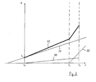
- the corresponding spring characteristics are shown in the diagram in Fig. 3 shown. In it, the vertical force F and horizontally the spring travel s is plotted vertically.
- the characteristic of the gas spring is indicated at 30.
- the spring characteristic of the outer coil spring 6 is shown at 31. Due to the prestressing, the coil spring 6 generates a spring force F s 0 already at the 0th
- the characteristic of the inner coil spring 7 is numbered 33. Due to the shorter overall length of the inner coil spring 7, this generates a force only from the spring travel s 1 .
- the designated 32 spring characteristic of the spring system 1 according to the invention consists of the sum of all these spring characteristics 30, 31 and 32nd
- Such a spring system 1 can be used, for example, that when closing a vehicle door shortly before the flap falls into a lock, the Force generated by the spring system 1 is significantly larger, so that the flap falls heavily braked into the lock.
- a sleeve 12 is pushed over at least a portion of the piston rod 4.
- this sleeve 12 prevents rattling of the inner coil spring 7 on the piston rod 4.
- the inner coil spring 7 is connected at one end fixed to the adjacent end face 13 of the cylinder 3. As a result, the inner helical spring 7 does not axially slide back and forth on the piston rod even when the piston rod 4 is fully extended.
Landscapes
- Engineering & Computer Science (AREA)
- General Engineering & Computer Science (AREA)
- Mechanical Engineering (AREA)
- Fluid-Damping Devices (AREA)
- Springs (AREA)
- Superstructure Of Vehicle (AREA)
Claims (8)
- Système de ressorts de volet pivotant, notamment de coffre de véhicule automobile comprenant :- au moins un ressort à gaz (2) qui, à l'état assemblé, agit à distance de l'axe de pivotement horizontal du volet d'une part, sur le corps de la carrosserie et d'autre part, sur le volet,- au moins un ressort hélicoïdal (6, 7) entourant exclusivement le segment d'une tige de piston (4) sortant du cylindre (3) du ressort à gaz (2), et le ressort hélicoïdal (6, 7) s'appuie directement ou indirectement contre la face frontale du cylindre (3) du ressort à gaz (2),
caractérisé par- deux ressorts hélicoïdaux (6, 7) l'un dans l'autre, entourant la tige de piston (4) sortant du cylindre (3) du ressort à gaz (2),- les deux ressorts hélicoïdaux (6, 7) ayant des longueurs différentes dans la direction axiale de la tige de piston (4), et- le ressort hélicoïdal (7) le plus court est fixé par une extrémité directement ou indirectement au cylindre (3) du ressort à gaz (2),- au moins un ressort hélicoïdal (6) est en précontrainte même lorsque la tige de piston (4) est complètement déployée. - Système de ressorts selon la revendication 1,
caractérisé en ce qu'
au moins le ressort hélicoïdal (6, 7) a une constante de ressort plus grande que le ressort à gaz (2). - Système de ressorts selon la revendication 1 ou 2,
caractérisé en ce qu'
au moins une partie de la longueur de la tige de piston (4) comporte un manchon (12), entre le ressort hélicoïdal intérieur (7) et la tige de piston (4). - Système de ressorts selon les revendications 1 à 3,
caractérisé en ce que
les deux ressorts hélicoïdaux (6, 7) sont des ressorts de compression. - Système de ressorts selon les revendications précédentes,
caractérisé en ce que
les ressorts hélicoïdaux (6, 7) sont entourés par un cylindre protecteur (8). - Système de ressorts selon la revendication 5,
caractérisé en ce que
le cylindre protecteur (8) coulisse télescopiquement sur le cylindre (3) du ressort à gaz (2). - Système de ressorts selon la revendication 6,
caractérisé en ce qu'
un joint (11) est fixé radialement sur le cylindre (3) du ressort à gaz (2), et lorsque la tige de piston (4) est complètement rétractée, le joint assure l'étanchéité entre le cylindre de protection (8) et le cylindre (3) du ressort à gaz (2). - Système de ressorts selon les revendications précédentes,
caractérisé en ce que
le système de ressorts (1) a un diamètre total inférieur à 22 mm.
Applications Claiming Priority (2)
| Application Number | Priority Date | Filing Date | Title |
|---|---|---|---|
| DE2001144791 DE10144791A1 (de) | 2001-09-12 | 2001-09-12 | Federsystem für eine schwenkbare Klappe eines Kraftfahrzeugs |
| DE10144791 | 2001-09-12 |
Publications (3)
| Publication Number | Publication Date |
|---|---|
| EP1293632A2 EP1293632A2 (fr) | 2003-03-19 |
| EP1293632A3 EP1293632A3 (fr) | 2005-12-28 |
| EP1293632B1 true EP1293632B1 (fr) | 2010-03-17 |
Family
ID=7698682
Family Applications (1)
| Application Number | Title | Priority Date | Filing Date |
|---|---|---|---|
| EP20020019652 Expired - Lifetime EP1293632B1 (fr) | 2001-09-12 | 2002-09-03 | Système de ressort pour le hayon pivotant d'un véhicule |
Country Status (2)
| Country | Link |
|---|---|
| EP (1) | EP1293632B1 (fr) |
| DE (2) | DE10144791A1 (fr) |
Families Citing this family (7)
| Publication number | Priority date | Publication date | Assignee | Title |
|---|---|---|---|---|
| FR3036127B1 (fr) * | 2015-05-11 | 2019-08-09 | Renault S.A.S | Actionneur pour ouverture automatique d'un hayon, muni d'un element elastique ayant une raideur progressive |
| DE102017131058A1 (de) * | 2017-12-22 | 2019-06-27 | Stabilus Gmbh | Klappenanordnung für ein Fahrzeug |
| WO2022038031A1 (fr) * | 2020-08-17 | 2022-02-24 | Brose Fahrzeugteile Se & Co. Kommanditgesellschaft, Bamberg | Dispositif d'entraînement conçu pour un ouvrant d'un véhicule automobile |
| JP7542431B2 (ja) | 2020-12-24 | 2024-08-30 | 株式会社クボタ | 作業車 |
| DE102022111137B4 (de) | 2021-05-21 | 2025-01-30 | Illinois Tool Works Inc. | Betätigungsvorrichtung zum öffnen und schliessen einer abdeckung in oder an einem fahrzeug |
| DE102024107478B3 (de) | 2024-03-15 | 2024-12-05 | Edscha Mechatronics Solutions GmbH | Federstütze für eine Fahrzeugklappe |
| DE102024107852B3 (de) | 2024-03-19 | 2025-01-02 | Edscha Mechatronics Solutions GmbH | Federstütze für eine Fahrzeugklappe |
Family Cites Families (6)
| Publication number | Priority date | Publication date | Assignee | Title |
|---|---|---|---|---|
| US3801085A (en) * | 1972-08-24 | 1974-04-02 | Gen Motors Corp | Gas spring booster arrangement |
| US4623132A (en) * | 1985-02-27 | 1986-11-18 | Fichtel & Sachs Industries, Inc. | Gas spring counterbalance system |
| DE3939118C2 (de) * | 1989-11-25 | 1998-04-09 | Stabilus Gmbh | Gasfeder mit abgestufter Kraftkennlinie |
| DE19646939C2 (de) * | 1996-11-13 | 2000-04-06 | Bayerische Motoren Werke Ag | Federsystem für eine schwenkbare Klappe eines Kraftfahrzeugs |
| DE19715860B4 (de) * | 1997-04-16 | 2005-11-03 | Roto Frank Ag | Dachfenster |
| AT414033B (de) * | 2001-01-09 | 2006-08-15 | Blum Gmbh Julius | Dämpfer, insbesondere für möbel |
-
2001
- 2001-09-12 DE DE2001144791 patent/DE10144791A1/de not_active Withdrawn
-
2002
- 2002-09-03 EP EP20020019652 patent/EP1293632B1/fr not_active Expired - Lifetime
- 2002-09-03 DE DE50214284T patent/DE50214284D1/de not_active Expired - Lifetime
Also Published As
| Publication number | Publication date |
|---|---|
| EP1293632A3 (fr) | 2005-12-28 |
| EP1293632A2 (fr) | 2003-03-19 |
| DE50214284D1 (de) | 2010-04-29 |
| DE10144791A1 (de) | 2003-03-27 |
Similar Documents
| Publication | Publication Date | Title |
|---|---|---|
| EP2212134B1 (fr) | Groupe d'axes pour un véhicule utilitaire et procédé pour fabriquer un groupe d'axes de ce type | |
| EP2550168B1 (fr) | Ressort pneumatique avec vanne intégrée | |
| EP2671001B1 (fr) | Ensemble piston-cylindre hydropneumatique | |
| EP2042771B2 (fr) | Amortisseur d'oscillations doté d'une butée | |
| EP2226453B1 (fr) | Entraînement par vis sans fin pour un élément mobile d'un véhicule automobile | |
| EP2394870B1 (fr) | Dispositif de ressort sur un clapet basculant d'un véhicule automobile | |
| EP0943525A2 (fr) | Colonne de direction d'un véhicule automobile | |
| DE102016210407A1 (de) | Frontspoiler-Anordnung mit als Überlastschutz vom Bewegungsantrieb entkoppelbarem Strömungsleitbauteil | |
| EP4153884B1 (fr) | Ressort à gaz et procédé de production d'un ressort à gaz | |
| DE102015009717A1 (de) | Ein- und ausfahrbare Stütze für schwenkbare Fahrzeugabdeckung | |
| DE102015109394A1 (de) | ZUG-/STOßEINRICHTUNG, INSBESONDERE FÜR MITTELPUFFERKUPPLUNGEN VON SPURGEFÜHRTEN FAHRZEUGEN | |
| DE102012013970A1 (de) | Vorrichtung zum Andrücken einer Zahnstange an ein Ritzel | |
| DE19646939C2 (de) | Federsystem für eine schwenkbare Klappe eines Kraftfahrzeugs | |
| EP1293632B1 (fr) | Système de ressort pour le hayon pivotant d'un véhicule | |
| DE10355444B4 (de) | Klappeneinheit | |
| DE102020119230A1 (de) | Antriebsanordnung für eine Klappe eines Kraftfahrzeugs | |
| DE102013007874A1 (de) | Türgelenkanordnung, Fahrzeugtür | |
| DE102021133006A1 (de) | Spindelanordnung | |
| DE102007032411A1 (de) | Kraftfahrzeug mit einer Fahrzeugtür | |
| EP2199729B1 (fr) | Ecoutille pour véhicules militaires | |
| DE102004026356B4 (de) | Zugfederanordnung | |
| DE10163386B4 (de) | Fensterheber mit einer Notschließeinrichtung für ein Kraftfahrzeug, insbesondere für ein Sicherheitsfahrzeug | |
| DE102012013964A1 (de) | Vorrichtung zum Andrücken einer Zahnstange an ein Ritzel | |
| EP1711392B1 (fr) | Direction a cremaillere destinee notamment a des camions legers | |
| DE102019128830A1 (de) | Antrieb zur Verstellung eines Verstellelements eines Kraftfahrzeugs |
Legal Events
| Date | Code | Title | Description |
|---|---|---|---|
| PUAI | Public reference made under article 153(3) epc to a published international application that has entered the european phase |
Free format text: ORIGINAL CODE: 0009012 |
|
| AK | Designated contracting states |
Kind code of ref document: A2 Designated state(s): AT BE BG CH CY CZ DE DK EE ES FI FR GB GR IE IT LI LU MC NL PT SE SK TR Designated state(s): AT BE BG CH CY CZ DE DK EE ES FI FR GB GR IE IT LI LU MC NL PT SE SK TR |
|
| AX | Request for extension of the european patent |
Extension state: AL LT LV MK RO SI |
|
| PUAL | Search report despatched |
Free format text: ORIGINAL CODE: 0009013 |
|
| AK | Designated contracting states |
Kind code of ref document: A3 Designated state(s): AT BE BG CH CY CZ DE DK EE ES FI FR GB GR IE IT LI LU MC NL PT SE SK TR |
|
| AX | Request for extension of the european patent |
Extension state: AL LT LV MK RO SI |
|
| 17P | Request for examination filed |
Effective date: 20060324 |
|
| AKX | Designation fees paid |
Designated state(s): DE FR GB |
|
| 17Q | First examination report despatched |
Effective date: 20071008 |
|
| GRAP | Despatch of communication of intention to grant a patent |
Free format text: ORIGINAL CODE: EPIDOSNIGR1 |
|
| GRAS | Grant fee paid |
Free format text: ORIGINAL CODE: EPIDOSNIGR3 |
|
| GRAA | (expected) grant |
Free format text: ORIGINAL CODE: 0009210 |
|
| AK | Designated contracting states |
Kind code of ref document: B1 Designated state(s): DE FR GB |
|
| REG | Reference to a national code |
Ref country code: GB Ref legal event code: FG4D Free format text: NOT ENGLISH |
|
| REF | Corresponds to: |
Ref document number: 50214284 Country of ref document: DE Date of ref document: 20100429 Kind code of ref document: P |
|
| PLBE | No opposition filed within time limit |
Free format text: ORIGINAL CODE: 0009261 |
|
| STAA | Information on the status of an ep patent application or granted ep patent |
Free format text: STATUS: NO OPPOSITION FILED WITHIN TIME LIMIT |
|
| 26N | No opposition filed |
Effective date: 20101220 |
|
| REG | Reference to a national code |
Ref country code: FR Ref legal event code: PLFP Year of fee payment: 15 |
|
| REG | Reference to a national code |
Ref country code: FR Ref legal event code: PLFP Year of fee payment: 16 |
|
| REG | Reference to a national code |
Ref country code: FR Ref legal event code: PLFP Year of fee payment: 17 |
|
| PGFP | Annual fee paid to national office [announced via postgrant information from national office to epo] |
Ref country code: FR Payment date: 20210927 Year of fee payment: 20 |
|
| PGFP | Annual fee paid to national office [announced via postgrant information from national office to epo] |
Ref country code: GB Payment date: 20210923 Year of fee payment: 20 Ref country code: DE Payment date: 20210904 Year of fee payment: 20 |
|
| REG | Reference to a national code |
Ref country code: DE Ref legal event code: R071 Ref document number: 50214284 Country of ref document: DE |
|
| REG | Reference to a national code |
Ref country code: GB Ref legal event code: PE20 Expiry date: 20220902 |
|
| PG25 | Lapsed in a contracting state [announced via postgrant information from national office to epo] |
Ref country code: GB Free format text: LAPSE BECAUSE OF EXPIRATION OF PROTECTION Effective date: 20220902 |
|
| P01 | Opt-out of the competence of the unified patent court (upc) registered |
Effective date: 20230502 |