EP2199729B1 - Ecoutille pour véhicules militaires - Google Patents
Ecoutille pour véhicules militaires Download PDFInfo
- Publication number
- EP2199729B1 EP2199729B1 EP09180134.0A EP09180134A EP2199729B1 EP 2199729 B1 EP2199729 B1 EP 2199729B1 EP 09180134 A EP09180134 A EP 09180134A EP 2199729 B1 EP2199729 B1 EP 2199729B1
- Authority
- EP
- European Patent Office
- Prior art keywords
- locking
- axis
- pivoting
- locking element
- hatch according
- Prior art date
- Legal status (The legal status is an assumption and is not a legal conclusion. Google has not performed a legal analysis and makes no representation as to the accuracy of the status listed.)
- Active
Links
Images




Classifications
-
- F—MECHANICAL ENGINEERING; LIGHTING; HEATING; WEAPONS; BLASTING
- F41—WEAPONS
- F41H—ARMOUR; ARMOURED TURRETS; ARMOURED OR ARMED VEHICLES; MEANS OF ATTACK OR DEFENCE, e.g. CAMOUFLAGE, IN GENERAL
- F41H5/00—Armour; Armour plates
- F41H5/22—Manhole covers, e.g. on tanks; Doors on armoured vehicles or structures
- F41H5/223—Manhole covers specially adapted for armoured or fighting vehicles
Definitions
- the invention relates to a pivot hatch according to the preamble of patent claim 1.
- Schwenkluken this type are used on military vehicles in particular as entry / exit hatches, through which a crew member of the vehicle in the vehicle can get on and off.
- the hatch cover is opened and locked in the open position via a locking element, so that a member of the vehicle crew can stick his head through the vehicle hatch to the vehicle's exterior, resulting in better visibility for this crew member,
- Locking elements for locking the hatch cover are known from the prior art, which can be moved back and forth in the direction of a locking axis in order to form a lock with a locking structure of the vehicle-fixed pivot bearing (see, eg EP 0 863 378 A2 ).
- Known locking elements extend in the direction of the locking axis and engage laterally in the locking structure, resulting in a positive locking of the hatch cover on the pivot bearing.
- the object of the invention is therefore to provide a pivot hatch in which a lock between the pivoting hatch cover and the pivot bearing is possible even at a more distant from the pivot axis of the pivot bearing locking axis.
- This object is achieved by a pivot hatch according to claim 1.
- Over the length of the locking element a reliable locking of the hatch cover can be realized even with larger distances between the locking axis and the pivot axis.
- extending transversely to the locking axis locking elements in contrast to purely axially extending locking elements not only on shear, but also on Bending are claimed, resulting in a favorable transfer of the particular in Studentslukefahren in rough terrain large forces.
- the hatch cover can be locked in two pivot positions via the locking element, wherein a first locking structure is provided for locking in the first pivot position and a second locking structure is provided for locking in the second pivot position.
- a first locking structure is provided for locking in the first pivot position
- a second locking structure is provided for locking in the second pivot position.
- the locking element can be moved back and forth in the direction of the locking axis by actuating an actuating element provided on the inside of the hatch cover.
- an actuating element provided on the inside of the hatch cover.
- the actuating element is coupled in such a way with an actuating bolt extending along the locking axis, that a rotational movement of the actuating element is converted into a translational movement of the actuating bolt.
- the actuating bolt may carry at one end of the locking element, which is entrained by the movement of the actuating bolt and in this way in the axial direction of the locking axis with the locking structures is engageable.
- An advantage for a reliable power transmission between the actuating element and the actuating bolt or the locking element is an embodiment, according to which the actuating element is coupled via a meshing with a toothed segment of the actuating bolt gear segment.
- the locking element has a guide portion and an engagement portion.
- the guide portion is guided over guide surfaces in the guide and that engages the engagement portion for locking the hatch cover via engagement surfaces in a pivotal position in a locking structure.
- the locking element has in this way a double function.
- the locking between the hatch cover and the pivot bearing is provided via the locking portion.
- the guide portion of the locking element is guided within the guide, so that there is a play-free transmission of forces over the guide portion.
- the engagement surfaces are inclined relative to each other, wherein in particular one of the two engagement surfaces is inclined relative to one of the guide surfaces and the second engagement surface is aligned parallel to the guide surfaces.
- An advantageous embodiment provides that the locking element is guided over the guide portion in the guide so that a torque support of the actuating bolt results, resulting in a reliable introduction of the forces and in particular the locking bolt is outside the power flow. This allows a smooth operation of the locking element.
- the locking structure is arranged on a bearing element for a Schwenkachsharm extending along the pivot axis.
- a further embodiment provides that the locking structure is a recess which is continuous parallel to the direction of the locking axis.
- the configuration of the locking structure as a recess passing through in the locking direction has the advantage that impurities accumulating within the locking structure are pushed out in the direction of entry when the locking element enters.
- the locking structure is a recess which opens in a direction radial to the pivot axis.
- the locking element engages from outside the pivot bearing in the locking structure and forms the lock.
- the locking element is loaded in the direction of the locking position via a spring, so that the lock is effected automatically by inserting the locking element into the locking structure as a result of the spring force, without requiring an actuation here.
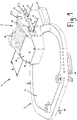
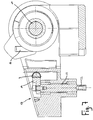
- FIG. 1 shows a Schwenkluke 1, as this particular as entry / exit hatch on military vehicles, in particular armored vehicles is used.
- the pivot hatch 1 has a solid hatch cover 3, which is arranged pivotably about a pivot axis S on a pivot bearing 2.
- the pivot bearing 2 is fixed to the vehicle on the outer contour of the vehicle.
- the hatch cover 3 In order to lock the hatch cover 3 having a considerable weight in the open position, the hatch cover 3 is provided with a locking element 4, which in locking structures 5.1, 5.2 of the pivot bearing 2 is locked or latched, so that after locking further pivotal movements of the hatch cover 3 are blocked relative to the pivot bearing 2.
- the pivot bearing 2 is formed by two bearing elements 15 which are fixed to the vehicle outer contour and form a bearing for a Schwenkachsêt 11.
- One of the two bearing elements 15 is provided with the two locking structures 5.1, 5.2, at an angle of 90 ° or 170 ° relative to the in FIG. 1 illustrated closed position of the hatch cover 3 are arranged.
- the locking element 4 is of elongated geometry and is arranged to be movable in the axial direction of the locking axis V back and forth. In the closed position according to FIG. 1 is the locking element 4 is not locked, but lies loosely against the side surface 26 of the bearing element 15 from the outside.
- the hatch cover 3 In the closed position, the hatch cover 3 is secured against opening by means of two closing elements 30 designed in the manner of a rotatable hand latch.
- the closing elements 30 are located on the inside 6 of the hatch cover 3 in the region of the hatch cover 3 facing away from the pivot bearing 2, cf. also Fig. 2 ,
- FIG. 1 It can also be seen that on the outside 7 of the hatch cover 3, a housing 17 is provided, in which the components required for locking the locking element 4 are housed.
- an actuating element 8 is provided, which is provided for actuating the locking element 4 and for releasing the lock.
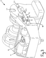
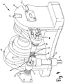
- FIG. 3 in which a cover plate 18 of the housing 17 is not located, is located in the interior of the housing 17 is a locking bolt 9 which is axially movable along the locking axis V back and forth and carries at its free end the locking element 4.
- the locking element 4 extends from the locking axis V in the direction of the pivot axis S. In the embodiment shown in the figures, the locking element 4 extends radially both to the locking axis V as well as to the pivot axis S.
- the locking element 4 extends transversely to the axis of the locking bolt 9 and is in the embodiment according to FIG. 3 releasably connected to the free end of the locking bolt 9.
- the locking element 4 has three sections.
- the section 4.2 forms the actual locking portion, which engages or snaps into the designed according to the type of recesses locking structures 5.1, 5.2 from the outside.
- To the engaging section 4.2 joins a guide section 4.1 of the locking element 4, which is guided within a bearing element 10, which is arranged in a side wall of the housing 17.
- a mounting portion 4.3 in which the locking element 4 is screwed by a bolt 19 with the locking pin 9.
- the guide section 4.1 of the locking element 4 slides within the locking element 10 via two mutually parallel guide surfaces 20.1, 20.2, so that a virtually backlash-free arrangement results, cf. also the representation in FIG. 9 ,
- the bearing element 10 is of overall horseshoe-shaped geometry and has a section corresponding to the geometry of the section 4.3, approximately hollow cylindrical section, and a two parallel surfaces having portion corresponding to the parallel guide surfaces 20.1, 20.2 of the locking element 4.
- the bearing element 10 is made of a suitable sliding bearing material.
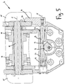
- actuator 8 is provided on the inside 6 of the hatch cover 3. This is connected via a square 22 with a shaft 23 which extends in a direction transverse to the hatch cover 3, see. Fig. 4 ,
- the shaft 23 penetrates the hatch cover 3 and projects into the housing 17 provided on its outer side 7.
- the shaft 23 is provided with a gear segment 14, which engages in a rack portion 13 of the locking bolt 9.
- about the meshing with the rack portion 13 gear segment 14 is a rotational movement of the operating handle 8 in a translational movement of the actuating bolt 9 and thus the locking element 4 along the locking axis V transferred, see. also FIGS. 6 and 7 ,
- the one end of a kind of actuating rod performing locking bolt 9 is guided in the locking direction in a bearing member 24 movable back and forth and force loaded by a spring 12 in the direction of the locking position.
- the other end of the locking bolt 9 is guided over the locking element 4 in the guide 10, so that the load of the hatch cover is not transmitted to the locking pin 9 and this is easy to move back and forth, see. also Fig. 5 ,
- the interior of the housing 17 is provided by a sealing ring 27 surrounding the actuating pin 9.
- the locking element 4 first slides along the outside 26 of the bearing element 15. Driven by the compression spring 12, it then locks on reaching the first locking structure 5.1 automatically in the locking structure 5.1, which is a bearing element 15 passing through the recess. The unlocking is then carried out by actuation of the actuating element 8 against the force of the spring 12, whereby the locking element 4 disengages from the locking structure 5.1 and the hatch cover 3 can be pivoted further or back to the closed position.
- FIG. 8 is a first open position shown, in which the hatch cover 3 is pivoted relative to the closed position by 90 ° upwards. As in FIG. 8 can be seen, in this position, the locking element 4 in the locking structure 5.1 engaged. Due to the play-free guidance of the locking element 4 within the bearing element 10, the introduced via the hatch cover 3 forces or moments are derived free of play on the bearing elements 15.
- the locking element 4 is shown in a perspective view.
- the locking element 4 is similar in cross section to the shape of a lock cylinder, wherein the locking element 4 has a construction with a total of three sections.
- section 4.2 forms the actual locking section. This has a smaller depth T 1 than the other sections 4.1, 4.3.
- the locking portion 4.2 is provided with engagement surfaces 21.1, 21.2, which are inclined relative to each other, see.
- FIG. 10 The guide section 4.1 has a greater depth T 2 than the locking section 4.2, so that the guide surfaces 20.1, 20.2 are always guided inside the bearing element 10 even when the locking structures 5.1, 5.2 lie outside the locking structures 5.1, 5.2.
- connection section 4.1 for connection to the locking pin 9, which has the greatest depth T 3 and has approximately a round cylindrical contour with an inside provided square 25.
- the locking element 4 extends in the region between the locking axis V and the pivot axis S of the pivot bearing 2, so that even with larger distances between the pivot axis S and the locking axis V a lock in the open positions is possible.
- the locking element 4 is not only subjected to shear but also to bending, so that even heavy-duty hatch cover 3 can be locked reliably via the locking element 4.
Landscapes
- Engineering & Computer Science (AREA)
- General Engineering & Computer Science (AREA)
- Lock And Its Accessories (AREA)
- Pivots And Pivotal Connections (AREA)
- Refuge Islands, Traffic Blockers, Or Guard Fence (AREA)
Claims (15)
- Ecoutille avec un panneau de cale (3) disposé de façon pivotante autour d'un axe de pivotement (S) par rapport à un palier pivotant (2), qui peut être verrouillé par un élément de verrouillage (4) dans au moins une position pivotée par rapport au palier pivotant (2), dans laquelle l'élément de verrouillage (4) est déplaçable en direction d'un axe de verrouillage (V) parallèle à l'axe de pivotement (S) et peut être mis en prise avec une structure de verrouillage (5.1, 5.2) du palier pivotant (2), caractérisée en ce que l'élément de verrouillage (4) s'étend à partir de l'axe de verrouillage (V) en direction de l'axe de pivotement (S) et en ce que la structure de verrouillage (5.1, 5.2) est un évidement s'ouvrant dans une direction radiale par rapport à l'axe de pivotement (S).
- Ecoutille selon la revendication 1, caractérisée en ce que le panneau de cale (3) peut être verrouillé dans deux positions pivotées au moyen de l'élément de verrouillage (4), dans laquelle il est prévu pour le verrouillage dans la première position pivotée une première structure de verrouillage (5.1) et pour le verrouillage dans la deuxième position pivotée une deuxième structure de verrouillage (5.2).
- Ecoutille selon la revendication 1 ou 2, caractérisée en ce que l'élément de verrouillage (4) est déplaçable en mouvement alternatif en direction de l'axe de verrouillage (V) par actionnement d'un élément d'actionnement (8) prévu sur le côté intérieur (6) du panneau de cale (3).
- Ecoutille selon la revendication 3, caractérisée en ce que l'élément d'actionnement (8) est couplé à un boulon d'actionnement (9) s'étendant le long de l'axe de verrouillage (V) de telle manière qu'un mouvement de rotation de l'élément d'actionnement (8) soit converti en un mouvement de translation du boulon d'actionnement (9).
- Ecoutille selon la revendication 4, caractérisée en ce que l'élément d'actionnement (8) est couplé au moyen d'un segment de roue dentée engrenant avec un segment denté du boulon d'actionnement (9).
- Ecoutille selon la revendication 4, caractérisée en ce que le mouvement du boulon de verrouillage (9) est guidé dans un guidage (10).
- Ecoutille selon l'une quelconque des revendications précédentes, caractérisée en ce que l'élément de verrouillage (4) présente une partie de guidage (4.1) et une partie de prise (4.2).
- Ecoutille selon la revendication 7, caractérisée en ce que la partie de guidage (4.1) est guidée par des faces de guidage (20.1, 20.2) dans le guidage (10) et en ce que la partie de prise (4.2) s'engage dans une structure de verrouillage (5.1, 5.2) pour le verrouillage du panneau de cale (3) par des faces de prise (21.1, 21.2) dans une position pivotée.
- Ecoutille selon la revendication 8, caractérisée en ce que les faces de guidage (20.1, 20.2) sont parallèles l'une à l'autre.
- Ecoutille selon la revendication 8 ou 9, caractérisée en ce que les faces de prise (21.1, 21.2) sont inclinées l'une par rapport à l'autre.
- Ecoutille selon l'une quelconque des revendications 8 à 10, caractérisée en ce que l'élément de verrouillage (4) est guidé sur la partie de guidage (4.1) dans le guidage (10) de telle manière qu'il en résulte un appui de couple de rotation du boulon d'actionnement (9).
- Ecoutille selon l'une quelconque des revendications précédentes, caractérisée en ce que la structure de verrouillage (5.1, 5.2) est disposée sur un élément de palier (10) pour un corps d'axe de pivotement (11) s'étendant le long de l'axe de pivotement (S).
- Ecoutille selon l'une quelconque des revendications précédentes, caractérisée en ce que la structure de verrouillage (5.1, 5.2) est un évidement continu parallèle à la direction de l'axe de verrouillage (V).
- Ecoutille selon l'une quelconque des revendications précédentes, caractérisée en ce que l'élément de verrouillage (4) s'engage de l'extérieur dans la structure de verrouillage (5.1, 5.2) et forme le verrouillage.
- Ecoutille selon l'une quelconque des revendications précédentes, caractérisée en ce que l'élément de verrouillage (4) est chargé par un ressort (12) en direction de la position de verrouillage.
Applications Claiming Priority (1)
| Application Number | Priority Date | Filing Date | Title |
|---|---|---|---|
| DE102008063769A DE102008063769B4 (de) | 2008-12-22 | 2008-12-22 | Schwenkluke, insbesondere für militärische Fahrzeuge |
Publications (3)
| Publication Number | Publication Date |
|---|---|
| EP2199729A2 EP2199729A2 (fr) | 2010-06-23 |
| EP2199729A3 EP2199729A3 (fr) | 2012-06-06 |
| EP2199729B1 true EP2199729B1 (fr) | 2018-02-21 |
Family
ID=41718353
Family Applications (1)
| Application Number | Title | Priority Date | Filing Date |
|---|---|---|---|
| EP09180134.0A Active EP2199729B1 (fr) | 2008-12-22 | 2009-12-21 | Ecoutille pour véhicules militaires |
Country Status (3)
| Country | Link |
|---|---|
| EP (1) | EP2199729B1 (fr) |
| DE (1) | DE102008063769B4 (fr) |
| ES (1) | ES2663413T3 (fr) |
Families Citing this family (3)
| Publication number | Priority date | Publication date | Assignee | Title |
|---|---|---|---|---|
| DE102011008699B4 (de) | 2011-01-15 | 2016-12-08 | Rheinmetall Landsysteme Gmbh | Schutzvorrichtung für insbesondere eine Luke |
| WO2014004254A1 (fr) * | 2012-06-26 | 2014-01-03 | Bae Systems Land & Armaments L. P. | Ecoutille divisée blindée |
| CN112777131B (zh) * | 2021-01-26 | 2022-06-07 | 益新制罐(惠州)有限公司 | 一种多边形儿童安全铁盒 |
Citations (14)
| Publication number | Priority date | Publication date | Assignee | Title |
|---|---|---|---|---|
| GB446340A (en) | 1934-10-20 | 1936-04-20 | Ceandess Ltd | Improvements in or relating to cap closures for petrol and oil tanks, radiators and the like |
| DE1584038A1 (de) | 1964-03-20 | 1969-03-27 | Bofors Ab | Anhaengevorrichtung fuer einen Deckel,insbesondere fuer den Deckel einer Einsteigoeffnung einer fahrbaren Kanone od.dgl. |
| GB1281084A (en) | 1969-02-25 | 1972-07-12 | Helio Mirror Company Ltd | Improvements in and relating to hatch assemblies for vehicles |
| US3721363A (en) | 1970-09-16 | 1973-03-20 | Gulf & Western Industries | Quick-opening manway closure |
| DE2403634A1 (de) | 1973-03-08 | 1974-09-12 | France Etat | Militaerische einrichtung mit beobachtungsstand |
| DE3908788A1 (de) | 1989-03-17 | 1990-09-20 | Rheinmetall Gmbh | Sperrvorrichtung fuer eine dachlukendeckelverriegelung |
| DE3908790A1 (de) | 1989-03-17 | 1990-09-20 | Rheinmetall Gmbh | Turminnenseitig bedienbarer mechanismus zum oeffnen und ablegen eines mit panzerschutz ausgeruesteten dachlukendeckels |
| DE3908789A1 (de) | 1989-03-17 | 1990-09-20 | Rheinmetall Gmbh | Verriegelungs- und aufschwenkmechanismus fuer einen mit panzerschutz ausgeruesteten dachlukendeckel |
| DE3938586A1 (de) | 1989-11-21 | 1991-05-23 | Wegmann & Co | Vorrichtung zum massenausgleich an gepanzerten lukendeckeln fuer kampffahrzeuge, insbesondere kampfpanzer |
| EP0863378A2 (fr) | 1997-03-05 | 1998-09-09 | Wegmann & Co. GmbH | Couvercle de trou d'homme pour véhicule blindé |
| EP1039259A2 (fr) | 1999-03-19 | 2000-09-27 | Krauss-Maffei Wegmann GmbH & Co. KG | Couvercle de trou d'homme pour véhicule blindé |
| DE10225617A1 (de) | 2002-06-07 | 2003-12-24 | Muhr & Bender Kg | Spanneinrichtung für Zugmittel, insbesondere Riemenspanneinrichtung |
| KR20070066681A (ko) | 2005-12-22 | 2007-06-27 | 두산인프라코어 주식회사 | 상하 열림각도 조정이 가능한 특수차량의 해치 개폐장치 |
| FR2920461A1 (fr) | 2007-08-30 | 2009-03-06 | Peugeot Citroen Automobiles Sa | Dispositif de maintien en position d'ouverture stable d'un ouvrant de vehicule automobile, en particulier d'un capot avant |
-
2008
- 2008-12-22 DE DE102008063769A patent/DE102008063769B4/de not_active Expired - Fee Related
-
2009
- 2009-12-21 EP EP09180134.0A patent/EP2199729B1/fr active Active
- 2009-12-21 ES ES09180134.0T patent/ES2663413T3/es active Active
Patent Citations (14)
| Publication number | Priority date | Publication date | Assignee | Title |
|---|---|---|---|---|
| GB446340A (en) | 1934-10-20 | 1936-04-20 | Ceandess Ltd | Improvements in or relating to cap closures for petrol and oil tanks, radiators and the like |
| DE1584038A1 (de) | 1964-03-20 | 1969-03-27 | Bofors Ab | Anhaengevorrichtung fuer einen Deckel,insbesondere fuer den Deckel einer Einsteigoeffnung einer fahrbaren Kanone od.dgl. |
| GB1281084A (en) | 1969-02-25 | 1972-07-12 | Helio Mirror Company Ltd | Improvements in and relating to hatch assemblies for vehicles |
| US3721363A (en) | 1970-09-16 | 1973-03-20 | Gulf & Western Industries | Quick-opening manway closure |
| DE2403634A1 (de) | 1973-03-08 | 1974-09-12 | France Etat | Militaerische einrichtung mit beobachtungsstand |
| DE3908788A1 (de) | 1989-03-17 | 1990-09-20 | Rheinmetall Gmbh | Sperrvorrichtung fuer eine dachlukendeckelverriegelung |
| DE3908790A1 (de) | 1989-03-17 | 1990-09-20 | Rheinmetall Gmbh | Turminnenseitig bedienbarer mechanismus zum oeffnen und ablegen eines mit panzerschutz ausgeruesteten dachlukendeckels |
| DE3908789A1 (de) | 1989-03-17 | 1990-09-20 | Rheinmetall Gmbh | Verriegelungs- und aufschwenkmechanismus fuer einen mit panzerschutz ausgeruesteten dachlukendeckel |
| DE3938586A1 (de) | 1989-11-21 | 1991-05-23 | Wegmann & Co | Vorrichtung zum massenausgleich an gepanzerten lukendeckeln fuer kampffahrzeuge, insbesondere kampfpanzer |
| EP0863378A2 (fr) | 1997-03-05 | 1998-09-09 | Wegmann & Co. GmbH | Couvercle de trou d'homme pour véhicule blindé |
| EP1039259A2 (fr) | 1999-03-19 | 2000-09-27 | Krauss-Maffei Wegmann GmbH & Co. KG | Couvercle de trou d'homme pour véhicule blindé |
| DE10225617A1 (de) | 2002-06-07 | 2003-12-24 | Muhr & Bender Kg | Spanneinrichtung für Zugmittel, insbesondere Riemenspanneinrichtung |
| KR20070066681A (ko) | 2005-12-22 | 2007-06-27 | 두산인프라코어 주식회사 | 상하 열림각도 조정이 가능한 특수차량의 해치 개폐장치 |
| FR2920461A1 (fr) | 2007-08-30 | 2009-03-06 | Peugeot Citroen Automobiles Sa | Dispositif de maintien en position d'ouverture stable d'un ouvrant de vehicule automobile, en particulier d'un capot avant |
Also Published As
| Publication number | Publication date |
|---|---|
| DE102008063769B4 (de) | 2011-02-17 |
| EP2199729A2 (fr) | 2010-06-23 |
| DE102008063769A1 (de) | 2010-06-24 |
| EP2199729A3 (fr) | 2012-06-06 |
| ES2663413T3 (es) | 2018-04-12 |
Similar Documents
| Publication | Publication Date | Title |
|---|---|---|
| EP2362041B1 (fr) | Verrouillage de protection contre les mines pour l'agencement sur des portes de véhicules militaires | |
| EP2291571B1 (fr) | Dispositif de fermeture comprenant un ressort à cliquet | |
| DE102010013715B4 (de) | Verriegelungsmechanismus für eine Luftfahrzeugtür, Verfahren zum Verriegeln einer Luftfahrzeugtür und Flugzeugtür | |
| EP2157396B1 (fr) | Porte de véhicule pour véhicules blindés comportant un pêne de protection contre les mines | |
| DE102009018188B4 (de) | Vorrichtung zum automatischen Schließen einer Fahrzeugtür | |
| DE102023109932B3 (de) | Antriebsvorrichtung mit Kopplungsvorrichtung für eine Fahrzeugklappe | |
| EP1767388A2 (fr) | Porte pivotante-coulissante pour véhicules de transport de personnes | |
| EP2199729B1 (fr) | Ecoutille pour véhicules militaires | |
| EP2096027B1 (fr) | Commande de clapets | |
| DE102010002736A1 (de) | Kraftfahrzeugschloss mit Kraftübertragung auf den Schlosskasten | |
| EP0918126A2 (fr) | Système d'actionnement pour pièces mobiles sur des véhicules. | |
| EP0428953A1 (fr) | Véhicule blindé de combat, en particulier char | |
| DE102005061127B4 (de) | Luftfahrzeugtür-Anordnung sowie Luftfahrzeugrumpf mit einer derartigen Luftfahrzeugtür-Anordnung | |
| DE10117769B4 (de) | Vorrichtung zur Unterstützung einer Öffnungsbewegung einer Fahrzeugklappe | |
| DE102016115622A1 (de) | Verriegelungssystem zur Verriegelung eines Deckels in einem Kraftfahrzeug | |
| EP3287579B1 (fr) | Dispositif de fermeture pour porte | |
| DE202007013330U1 (de) | Kraftfahrzeugschloß | |
| DE10008497B4 (de) | Feststellmechanismus für Schiebetür | |
| EP1293632A2 (fr) | Système de ressort pour le hayon pivotant d'un véhicule | |
| EP3617432B1 (fr) | Dispositif de fermeture pour une porte | |
| EP1150090B1 (fr) | Dispsitif pour l'ouverture et la fermeture d'un couvercle d'une trappe d'un véhicule de combat, en particulier un char | |
| DE102010036607A1 (de) | Minenschutzverriegelung und Verfahren zur Entriegelung einer Minenschutzverriegelung | |
| DE102022101040A1 (de) | Gepanzertes Fahrzeug mit Notausstiegsluke | |
| EP2105558A2 (fr) | Serrure avec un agencement de sécurité | |
| DE102013009921A1 (de) | Türantrieb für eine Schwenkschiebetür eines Fahrzeugs |
Legal Events
| Date | Code | Title | Description |
|---|---|---|---|
| PUAI | Public reference made under article 153(3) epc to a published international application that has entered the european phase |
Free format text: ORIGINAL CODE: 0009012 |
|
| AK | Designated contracting states |
Kind code of ref document: A2 Designated state(s): AT BE BG CH CY CZ DE DK EE ES FI FR GB GR HR HU IE IS IT LI LT LU LV MC MK MT NL NO PL PT RO SE SI SK SM TR |
|
| AX | Request for extension of the european patent |
Extension state: AL BA RS |
|
| PUAL | Search report despatched |
Free format text: ORIGINAL CODE: 0009013 |
|
| AK | Designated contracting states |
Kind code of ref document: A3 Designated state(s): AT BE BG CH CY CZ DE DK EE ES FI FR GB GR HR HU IE IS IT LI LT LU LV MC MK MT NL NO PL PT RO SE SI SK SM TR |
|
| AX | Request for extension of the european patent |
Extension state: AL BA RS |
|
| RIC1 | Information provided on ipc code assigned before grant |
Ipc: F41H 5/22 20060101AFI20120503BHEP |
|
| 17P | Request for examination filed |
Effective date: 20121130 |
|
| 17Q | First examination report despatched |
Effective date: 20131010 |
|
| GRAP | Despatch of communication of intention to grant a patent |
Free format text: ORIGINAL CODE: EPIDOSNIGR1 |
|
| STAA | Information on the status of an ep patent application or granted ep patent |
Free format text: STATUS: GRANT OF PATENT IS INTENDED |
|
| INTG | Intention to grant announced |
Effective date: 20170321 |
|
| GRAJ | Information related to disapproval of communication of intention to grant by the applicant or resumption of examination proceedings by the epo deleted |
Free format text: ORIGINAL CODE: EPIDOSDIGR1 |
|
| STAA | Information on the status of an ep patent application or granted ep patent |
Free format text: STATUS: EXAMINATION IS IN PROGRESS |
|
| GRAP | Despatch of communication of intention to grant a patent |
Free format text: ORIGINAL CODE: EPIDOSNIGR1 |
|
| STAA | Information on the status of an ep patent application or granted ep patent |
Free format text: STATUS: GRANT OF PATENT IS INTENDED |
|
| INTC | Intention to grant announced (deleted) | ||
| INTG | Intention to grant announced |
Effective date: 20170606 |
|
| GRAJ | Information related to disapproval of communication of intention to grant by the applicant or resumption of examination proceedings by the epo deleted |
Free format text: ORIGINAL CODE: EPIDOSDIGR1 |
|
| STAA | Information on the status of an ep patent application or granted ep patent |
Free format text: STATUS: EXAMINATION IS IN PROGRESS |
|
| GRAP | Despatch of communication of intention to grant a patent |
Free format text: ORIGINAL CODE: EPIDOSNIGR1 |
|
| STAA | Information on the status of an ep patent application or granted ep patent |
Free format text: STATUS: GRANT OF PATENT IS INTENDED |
|
| INTC | Intention to grant announced (deleted) | ||
| INTG | Intention to grant announced |
Effective date: 20170925 |
|
| GRAS | Grant fee paid |
Free format text: ORIGINAL CODE: EPIDOSNIGR3 |
|
| GRAA | (expected) grant |
Free format text: ORIGINAL CODE: 0009210 |
|
| STAA | Information on the status of an ep patent application or granted ep patent |
Free format text: STATUS: THE PATENT HAS BEEN GRANTED |
|
| AK | Designated contracting states |
Kind code of ref document: B1 Designated state(s): AT BE BG CH CY CZ DE DK EE ES FI FR GB GR HR HU IE IS IT LI LT LU LV MC MK MT NL NO PL PT RO SE SI SK SM TR |
|
| REG | Reference to a national code |
Ref country code: GB Ref legal event code: FG4D Free format text: NOT ENGLISH |
|
| REG | Reference to a national code |
Ref country code: CH Ref legal event code: EP |
|
| REG | Reference to a national code |
Ref country code: AT Ref legal event code: REF Ref document number: 972232 Country of ref document: AT Kind code of ref document: T Effective date: 20180315 |
|
| REG | Reference to a national code |
Ref country code: IE Ref legal event code: FG4D Free format text: LANGUAGE OF EP DOCUMENT: GERMAN |
|
| REG | Reference to a national code |
Ref country code: DE Ref legal event code: R096 Ref document number: 502009014739 Country of ref document: DE |
|
| REG | Reference to a national code |
Ref country code: SE Ref legal event code: TRGR |
|
| REG | Reference to a national code |
Ref country code: ES Ref legal event code: FG2A Ref document number: 2663413 Country of ref document: ES Kind code of ref document: T3 Effective date: 20180412 |
|
| REG | Reference to a national code |
Ref country code: NL Ref legal event code: MP Effective date: 20180221 |
|
| REG | Reference to a national code |
Ref country code: LT Ref legal event code: MG4D |
|
| PG25 | Lapsed in a contracting state [announced via postgrant information from national office to epo] |
Ref country code: FI Free format text: LAPSE BECAUSE OF FAILURE TO SUBMIT A TRANSLATION OF THE DESCRIPTION OR TO PAY THE FEE WITHIN THE PRESCRIBED TIME-LIMIT Effective date: 20180221 Ref country code: LT Free format text: LAPSE BECAUSE OF FAILURE TO SUBMIT A TRANSLATION OF THE DESCRIPTION OR TO PAY THE FEE WITHIN THE PRESCRIBED TIME-LIMIT Effective date: 20180221 Ref country code: HR Free format text: LAPSE BECAUSE OF FAILURE TO SUBMIT A TRANSLATION OF THE DESCRIPTION OR TO PAY THE FEE WITHIN THE PRESCRIBED TIME-LIMIT Effective date: 20180221 Ref country code: NO Free format text: LAPSE BECAUSE OF FAILURE TO SUBMIT A TRANSLATION OF THE DESCRIPTION OR TO PAY THE FEE WITHIN THE PRESCRIBED TIME-LIMIT Effective date: 20180521 Ref country code: NL Free format text: LAPSE BECAUSE OF FAILURE TO SUBMIT A TRANSLATION OF THE DESCRIPTION OR TO PAY THE FEE WITHIN THE PRESCRIBED TIME-LIMIT Effective date: 20180221 Ref country code: CY Free format text: LAPSE BECAUSE OF FAILURE TO SUBMIT A TRANSLATION OF THE DESCRIPTION OR TO PAY THE FEE WITHIN THE PRESCRIBED TIME-LIMIT Effective date: 20180221 |
|
| PG25 | Lapsed in a contracting state [announced via postgrant information from national office to epo] |
Ref country code: BG Free format text: LAPSE BECAUSE OF FAILURE TO SUBMIT A TRANSLATION OF THE DESCRIPTION OR TO PAY THE FEE WITHIN THE PRESCRIBED TIME-LIMIT Effective date: 20180521 Ref country code: LV Free format text: LAPSE BECAUSE OF FAILURE TO SUBMIT A TRANSLATION OF THE DESCRIPTION OR TO PAY THE FEE WITHIN THE PRESCRIBED TIME-LIMIT Effective date: 20180221 Ref country code: GR Free format text: LAPSE BECAUSE OF FAILURE TO SUBMIT A TRANSLATION OF THE DESCRIPTION OR TO PAY THE FEE WITHIN THE PRESCRIBED TIME-LIMIT Effective date: 20180522 |
|
| PG25 | Lapsed in a contracting state [announced via postgrant information from national office to epo] |
Ref country code: MT Free format text: LAPSE BECAUSE OF FAILURE TO SUBMIT A TRANSLATION OF THE DESCRIPTION OR TO PAY THE FEE WITHIN THE PRESCRIBED TIME-LIMIT Effective date: 20180221 |
|
| PG25 | Lapsed in a contracting state [announced via postgrant information from national office to epo] |
Ref country code: EE Free format text: LAPSE BECAUSE OF FAILURE TO SUBMIT A TRANSLATION OF THE DESCRIPTION OR TO PAY THE FEE WITHIN THE PRESCRIBED TIME-LIMIT Effective date: 20180221 Ref country code: RO Free format text: LAPSE BECAUSE OF FAILURE TO SUBMIT A TRANSLATION OF THE DESCRIPTION OR TO PAY THE FEE WITHIN THE PRESCRIBED TIME-LIMIT Effective date: 20180221 Ref country code: PL Free format text: LAPSE BECAUSE OF FAILURE TO SUBMIT A TRANSLATION OF THE DESCRIPTION OR TO PAY THE FEE WITHIN THE PRESCRIBED TIME-LIMIT Effective date: 20180221 |
|
| REG | Reference to a national code |
Ref country code: DE Ref legal event code: R026 Ref document number: 502009014739 Country of ref document: DE |
|
| PG25 | Lapsed in a contracting state [announced via postgrant information from national office to epo] |
Ref country code: CZ Free format text: LAPSE BECAUSE OF FAILURE TO SUBMIT A TRANSLATION OF THE DESCRIPTION OR TO PAY THE FEE WITHIN THE PRESCRIBED TIME-LIMIT Effective date: 20180221 Ref country code: SK Free format text: LAPSE BECAUSE OF FAILURE TO SUBMIT A TRANSLATION OF THE DESCRIPTION OR TO PAY THE FEE WITHIN THE PRESCRIBED TIME-LIMIT Effective date: 20180221 Ref country code: DK Free format text: LAPSE BECAUSE OF FAILURE TO SUBMIT A TRANSLATION OF THE DESCRIPTION OR TO PAY THE FEE WITHIN THE PRESCRIBED TIME-LIMIT Effective date: 20180221 Ref country code: SM Free format text: LAPSE BECAUSE OF FAILURE TO SUBMIT A TRANSLATION OF THE DESCRIPTION OR TO PAY THE FEE WITHIN THE PRESCRIBED TIME-LIMIT Effective date: 20180221 |
|
| PLBI | Opposition filed |
Free format text: ORIGINAL CODE: 0009260 |
|
| PLAX | Notice of opposition and request to file observation + time limit sent |
Free format text: ORIGINAL CODE: EPIDOSNOBS2 |
|
| 26 | Opposition filed |
Opponent name: RHEINMETALL LANDSYSTEME GMBH Effective date: 20181121 |
|
| PG25 | Lapsed in a contracting state [announced via postgrant information from national office to epo] |
Ref country code: SI Free format text: LAPSE BECAUSE OF FAILURE TO SUBMIT A TRANSLATION OF THE DESCRIPTION OR TO PAY THE FEE WITHIN THE PRESCRIBED TIME-LIMIT Effective date: 20180221 |
|
| PLBB | Reply of patent proprietor to notice(s) of opposition received |
Free format text: ORIGINAL CODE: EPIDOSNOBS3 |
|
| PG25 | Lapsed in a contracting state [announced via postgrant information from national office to epo] |
Ref country code: MC Free format text: LAPSE BECAUSE OF FAILURE TO SUBMIT A TRANSLATION OF THE DESCRIPTION OR TO PAY THE FEE WITHIN THE PRESCRIBED TIME-LIMIT Effective date: 20180221 Ref country code: LU Free format text: LAPSE BECAUSE OF NON-PAYMENT OF DUE FEES Effective date: 20181221 |
|
| REG | Reference to a national code |
Ref country code: IE Ref legal event code: MM4A |
|
| REG | Reference to a national code |
Ref country code: BE Ref legal event code: MM Effective date: 20181231 |
|
| PG25 | Lapsed in a contracting state [announced via postgrant information from national office to epo] |
Ref country code: IE Free format text: LAPSE BECAUSE OF NON-PAYMENT OF DUE FEES Effective date: 20181221 |
|
| PG25 | Lapsed in a contracting state [announced via postgrant information from national office to epo] |
Ref country code: BE Free format text: LAPSE BECAUSE OF NON-PAYMENT OF DUE FEES Effective date: 20181231 |
|
| REG | Reference to a national code |
Ref country code: AT Ref legal event code: MM01 Ref document number: 972232 Country of ref document: AT Kind code of ref document: T Effective date: 20181221 |
|
| PG25 | Lapsed in a contracting state [announced via postgrant information from national office to epo] |
Ref country code: TR Free format text: LAPSE BECAUSE OF FAILURE TO SUBMIT A TRANSLATION OF THE DESCRIPTION OR TO PAY THE FEE WITHIN THE PRESCRIBED TIME-LIMIT Effective date: 20180221 |
|
| PG25 | Lapsed in a contracting state [announced via postgrant information from national office to epo] |
Ref country code: AT Free format text: LAPSE BECAUSE OF NON-PAYMENT OF DUE FEES Effective date: 20181221 |
|
| PG25 | Lapsed in a contracting state [announced via postgrant information from national office to epo] |
Ref country code: PT Free format text: LAPSE BECAUSE OF FAILURE TO SUBMIT A TRANSLATION OF THE DESCRIPTION OR TO PAY THE FEE WITHIN THE PRESCRIBED TIME-LIMIT Effective date: 20180221 |
|
| PG25 | Lapsed in a contracting state [announced via postgrant information from national office to epo] |
Ref country code: HU Free format text: LAPSE BECAUSE OF FAILURE TO SUBMIT A TRANSLATION OF THE DESCRIPTION OR TO PAY THE FEE WITHIN THE PRESCRIBED TIME-LIMIT; INVALID AB INITIO Effective date: 20091221 Ref country code: MK Free format text: LAPSE BECAUSE OF NON-PAYMENT OF DUE FEES Effective date: 20180221 |
|
| PG25 | Lapsed in a contracting state [announced via postgrant information from national office to epo] |
Ref country code: IS Free format text: LAPSE BECAUSE OF FAILURE TO SUBMIT A TRANSLATION OF THE DESCRIPTION OR TO PAY THE FEE WITHIN THE PRESCRIBED TIME-LIMIT Effective date: 20180621 |
|
| REG | Reference to a national code |
Ref country code: DE Ref legal event code: R100 Ref document number: 502009014739 Country of ref document: DE |
|
| PLCK | Communication despatched that opposition was rejected |
Free format text: ORIGINAL CODE: EPIDOSNREJ1 |
|
| PLBN | Opposition rejected |
Free format text: ORIGINAL CODE: 0009273 |
|
| STAA | Information on the status of an ep patent application or granted ep patent |
Free format text: STATUS: OPPOSITION REJECTED |
|
| 27O | Opposition rejected |
Effective date: 20220223 |
|
| P01 | Opt-out of the competence of the unified patent court (upc) registered |
Effective date: 20230517 |
|
| REG | Reference to a national code |
Ref country code: DE Ref legal event code: R081 Ref document number: 502009014739 Country of ref document: DE Owner name: KNDS DEUTSCHLAND GMBH & CO. KG, DE Free format text: FORMER OWNER: KRAUSS-MAFFEI WEGMANN GMBH & CO. KG, 80997 MUENCHEN, DE |
|
| REG | Reference to a national code |
Ref country code: ES Ref legal event code: PC2A Owner name: KNDS DEUTSCHLAND GMBH & CO. KG Effective date: 20250304 |
|
| REG | Reference to a national code |
Ref country code: CH Ref legal event code: U11 Free format text: ST27 STATUS EVENT CODE: U-0-0-U10-U11 (AS PROVIDED BY THE NATIONAL OFFICE) Effective date: 20260101 |
|
| PGFP | Annual fee paid to national office [announced via postgrant information from national office to epo] |
Ref country code: GB Payment date: 20251218 Year of fee payment: 17 |
|
| PGFP | Annual fee paid to national office [announced via postgrant information from national office to epo] |
Ref country code: FR Payment date: 20251218 Year of fee payment: 17 |
|
| PGFP | Annual fee paid to national office [announced via postgrant information from national office to epo] |
Ref country code: SE Payment date: 20251217 Year of fee payment: 17 |
|
| PGFP | Annual fee paid to national office [announced via postgrant information from national office to epo] |
Ref country code: ES Payment date: 20260119 Year of fee payment: 17 |
|
| PGFP | Annual fee paid to national office [announced via postgrant information from national office to epo] |
Ref country code: DE Payment date: 20251231 Year of fee payment: 17 |
|
| PGFP | Annual fee paid to national office [announced via postgrant information from national office to epo] |
Ref country code: IT Payment date: 20251231 Year of fee payment: 17 |
|
| PGFP | Annual fee paid to national office [announced via postgrant information from national office to epo] |
Ref country code: CH Payment date: 20260101 Year of fee payment: 17 |