EP1293746A2 - Distributeur d'air comprimé à fonctionnement automatique - Google Patents
Distributeur d'air comprimé à fonctionnement automatique Download PDFInfo
- Publication number
- EP1293746A2 EP1293746A2 EP02447176A EP02447176A EP1293746A2 EP 1293746 A2 EP1293746 A2 EP 1293746A2 EP 02447176 A EP02447176 A EP 02447176A EP 02447176 A EP02447176 A EP 02447176A EP 1293746 A2 EP1293746 A2 EP 1293746A2
- Authority
- EP
- European Patent Office
- Prior art keywords
- piston
- cylinder
- distributor
- chamber
- valve
- Prior art date
- Legal status (The legal status is an assumption and is not a legal conclusion. Google has not performed a legal analysis and makes no representation as to the accuracy of the status listed.)
- Granted
Links
Images

Classifications
-
- F—MECHANICAL ENGINEERING; LIGHTING; HEATING; WEAPONS; BLASTING
- F41—WEAPONS
- F41B—WEAPONS FOR PROJECTING MISSILES WITHOUT USE OF EXPLOSIVE OR COMBUSTIBLE PROPELLANT CHARGE; WEAPONS NOT OTHERWISE PROVIDED FOR
- F41B11/00—Compressed-gas guns, e.g. air guns; Steam guns
- F41B11/70—Details not provided for in F41B11/50 or F41B11/60
- F41B11/71—Electric or electronic control systems, e.g. for safety purposes
-
- F—MECHANICAL ENGINEERING; LIGHTING; HEATING; WEAPONS; BLASTING
- F41—WEAPONS
- F41B—WEAPONS FOR PROJECTING MISSILES WITHOUT USE OF EXPLOSIVE OR COMBUSTIBLE PROPELLANT CHARGE; WEAPONS NOT OTHERWISE PROVIDED FOR
- F41B11/00—Compressed-gas guns, e.g. air guns; Steam guns
- F41B11/50—Magazines for compressed-gas guns; Arrangements for feeding or loading projectiles from magazines
- F41B11/57—Electronic or electric systems for feeding or loading
-
- F—MECHANICAL ENGINEERING; LIGHTING; HEATING; WEAPONS; BLASTING
- F41—WEAPONS
- F41B—WEAPONS FOR PROJECTING MISSILES WITHOUT USE OF EXPLOSIVE OR COMBUSTIBLE PROPELLANT CHARGE; WEAPONS NOT OTHERWISE PROVIDED FOR
- F41B11/00—Compressed-gas guns, e.g. air guns; Steam guns
- F41B11/70—Details not provided for in F41B11/50 or F41B11/60
- F41B11/72—Valves; Arrangement of valves
- F41B11/721—Valves; Arrangement of valves for controlling gas pressure for both firing the projectile and for loading or feeding
Definitions
- the present invention relates to a compressed air or gas distributor placed or not at the end of a cylinder piston and which, after its activation, has a automatic operation caused by pressure and air depression in the cylinder.
- the present invention also relates to an achievement in kit form or integrated into everything mobile assembly driven by compressed air or pneumatic pressure (possibly pressurized gas other than air).
- compressed air by a means mechanical implemented by the operator at the time of charging (hand pumping), or a compressed gas, such as that the carbon dioxide in a cartridge is distributed from a storage chamber to the barrel of tear. This distribution is done by means of a valve actuated by pressing the trigger.
- US patent US-A-5,400 536 describes a rotary and double barrel pistol action, presenting a cylinder in line with the barrel for the projectile fire.
- a rod secured to the piston of the cylinder is struck by the dog, which opens the valve and releases pressurized gas into the barrel.
- U.S. Patent US-A-5,613,483 discloses assembling a piston and a cylinder for a handgun gas.
- the piston can move back and forth, between a loading position and a firing position.
- the cylinder has two chambers through which moves the piston.
- the piston When the piston is in the position of loading, the cylinder is in communication via the first chamber with a gas supply device under pressure. This position of the piston prevents any communication between the two rooms.
- the piston rod is provided with a passage section at the contact with the cylinder which extends from longitudinally.
- document US-A-5,363,834 describes a weapon having a first operating mode for the propulsion of a projectile by compressed gas contained in a cartridge and a second operating mode for compressed air propulsion generated by a manual pumping.
- the aim is to be able to remedy a failure of the compressed gas supply system (dioxide of carbon).
- a manual switch operable by the shooter allows switching from one operating mode to another, by bringing a storage chamber into contact with either the gas compressed, or with the compressed air obtained by pumping. then from the shot, the dog strikes a cylinder piston element which releases pressurized air or gas to the barrel tear.
- the present invention aims to provide a jack and its compressed gas distributor, preferably in line, fully automatic after activation by an initial impulse.
- the invention has the complementary aim of ability to provide, for certain applications, such a cylinder and its distributor in kit form, easily adaptable on existing equipment.
- the invention also aims to provide such a distributor which is compact, that is to say causing a very small increase in the length of the cylinder by distributor integration, simple and easy to production.
- the invention aims to propose a pneumatic automatic distributor usable in a large number of technical fields and not limited to specific armaments sector.
- the present invention relates to a automatic device for the distribution of compressed gas, for example air or compressed carbon dioxide, comprising a cylinder constituted a cylinder in which can slide a piston provided a piston head, said cylinder being provided with a closable front end, called distributor support, a distributor located in the extension of said cylinder.
- the dispenser can be ordered directly by the front of the piston.
- the distributor has a gas supply compressed, a chamber that can contain said gas under pressure being dynamically located between the end lockable cylinder and piston head.
- the device comprises a valve capable of open and close along the cylinder axis and a seal double allowing the opening and closing of the arrival of compressed gas, the valve being provided with a spring reminder such that at equilibrium, it is detached from the joint double, rear side, the double seal being provided with a return spring such that at equilibrium, it closes the arrival compressed gas.
- the piston head can come into contact at the front of the cylinder with the valve, this which causes the integral recoil of said valve and the double seal with stop against the distributor support, this which causes admission by a compressed gas supply in the bedroom.
- pressurized gas escapes either through outlet of the piston out of the cylinder, either through a fitted orifice in the cylinder, the piston then remaining inside the cylinder.
- the piston is provided with a return spring which tends to bring it back towards its equilibrium position at the front of the cylinder.
- the bedroom not being or being weakly pressurized and the piston no longer in contact with the valve, the valve and the double seal are in their equilibrium position under the effect of their respective return springs and the valve is detached from the double seal, allowing a exhaust of gas contained in the chamber through a orifice provided in the wall of the distributor support, the double seal being in the closed position of the arrival of gas under pressure.
- the contact between the piston and the valve is produced by means of a control striker capable of slide freely inside the piston, the part rear of the striker having been struck initially by the hammer.
- the dispenser can be controlled by a traction device placed in front the assembly constituted by the distributor and its cylinder.
- the traction device replaces the percussion initial piston with a hammer.
- Another advantage is that ability to easily reset activation element (hammer) of the distributor by the recoil of the piston.
- the cylinder / distributor device of the present invention is advantageously usable with pistol-type weapons (with slide) or rifle (with movable breech).
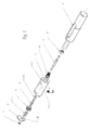
- Figure 1 shows an exploded view with nomenclature according to the principle of control by a striker passing through the piston of the jack according to the invention.
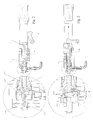
- Figure 2 shows a sectional view longitudinal of the different parts of the cylinder / distributor of Figure 1, as well as a detailed view, in the position of rest, with the compressed air supply blocked.
- Figure 3 shows a sectional view longitudinal of the different parts of the cylinder / distributor of Figure 1, as well as a detailed view, in position activation of the distributor for air opening.
- Figure 4 shows a sectional view longitudinal of the different parts of the cylinder / distributor of Figure 1, as well as a detailed view, in position recoil of the piston, with the compressed air supply open.
- Figure 5 shows a sectional view longitudinal of the different parts of the cylinder / distributor of Figure 1, as well as a detailed view, in position piston outside the cylinder tube, the compressed air supply being closed.
- Figure 6 shows a sectional view longitudinal of the different cylinder / distributor parts Figure 1, and a detailed view, in the return position the piston of the cylinder moved by its spring with exhaust from compressed air through the distributor.
- the air distribution device automatic tablet according to the invention can be produced in kit form or integrated into any mechanism such as rifle or pistol especially for shooting simulation or in any mechanism depending on the possibilities exploitation of the advantages of the invention.
- activation initial of the dispenser is obtained by percussion of a striker 9 which can slide freely inside a piston 80, by means of a hammer (or hammer) 15 which can be an original part of a weapon or equipped device automatic compressed air distributor according to the invention.
- Percussion is by pivoting towards the front of the hammer 15 in a recess of the piston body 8.
- FIG. 3 shows the position opening the air supply.
- a striker 9 which passes through the piston 80 of the jack and is controlled by a hammer 15 which strikes said striker 9.
- the latter transmits its linear movement at valve 5 of the distributor.
- the valve 5 then comes into contact with the seal of distributor 3, the latter moving to the left, this which allows compressed air to pass between the assembly attached seal 3 - valve 5 and piston head 11 of cylinder.
- Figure 5 shows the position of depressurization in the cylinder.
- the piston 80 recedes cylinder the latter can either exit the cylinder tube or cylinder 1, or stay in the cylinder thanks to a lateral air exhaust 12 located in the cylinder tube 1. In both cases, this has the effect of causing the pressure in the cylinder tube 1 and, at the same time, decrease the pressure on the distributor seal assembly 3 and valve 5.
- the assembly 3.5 can then, under the effect of respective springs 4.6 of the two parts 3.5 resume its initial position to the right (figure 6), which closes compressed air supply thanks to the double circular joint distributor 3. This also allows the escape of air still in room 10 when returning piston 80 of the cylinder which, moved by its spring (not shown) returns to its initial rest position towards the left.
- the air exhaust is achieved by detaching the valve 5 from the seal distributor 3, through the lower hole 20 of the support of the distributor 2 (see detail view of FIG. 6).
- the compressed air supply remains blocked at this stage and the system returned to its original rest position. The complete sequence of cylinder and distributor is therefore carried out automatically since it is initiated only by the impulse of the hammer 15, without that any other intervention is necessary.
- the striker part 9 could be absent and be replaced by direct contact between the piston 80 of the jack and the valve 5, which would have effect when closing the cylinder to the left, would automatically have all the functions available illustrated in Figures 3 to 6. To stop, in this configuration, the operating cycle, just to interrupt the piston of the cylinder tube before its contact with valve 5.
- the device of the invention can be produced as a kit to be mounted directly in fire simulation weapons or be adaptable to any other mechanism, either as a kit, or integrated into a more complex, whether or not requiring modifications to the system original.
Landscapes
- Engineering & Computer Science (AREA)
- General Engineering & Computer Science (AREA)
- Percussive Tools And Related Accessories (AREA)
- Portable Nailing Machines And Staplers (AREA)
- Fluid-Driven Valves (AREA)
- Organic Low-Molecular-Weight Compounds And Preparation Thereof (AREA)
- Toys (AREA)
- Control Of The Air-Fuel Ratio Of Carburetors (AREA)
- Eye Examination Apparatus (AREA)
Abstract
- déplacement du piston (80) vers l'avant, admission de gaz comprimé dans la chambre (13) et pressurisation de celle-ci,
- recul du piston (80) vers l'arrière, échappement du gaz comprimé contenu dans la chambre (13) et dépressurisation de celle-ci,
- retour du piston (80) vers l'avant, fermeture de l'arrivée de gaz comprimé (14), échappement vers l'avant du gaz résiduel contenu dans la chambre (13) et retour du dispositif à sa position initiale.
Description
- déplacement du piston vers l'avant, admission de gaz comprimé dans la chambre et pressurisation de celle-ci,
- recul du piston vers l'arrière, échappement du gaz comprimé contenu dans la chambre et dépressurisation de celle-ci,
- retour du piston vers l'avant, fermeture de l'arrivée de gaz comprimé, échappement vers l'avant du gaz résiduel contenu dans la chambre et retour du dispositif à sa position initiale.
- grande compacité vu la très faible augmentation de la longueur du vérin par l'intégration du distributeur ;
- fonction ouverture de l'arrivée d'air avec maintien pendant toute la durée du déplacement du piston vers l'arrière ;
- fonction fermeture automatique de l'arrivée d'air comprimé par dépression de chambre ;
- fonction échappement de l'air automatique lors du retour de piston ;
- possibilité de réalisation sous forme de kit ;
- réarmement automatique du marteau ;
- possibilité de déplacement de pièces mobiles, non exclusivement limité à des fins d'alimentation pneumatique dans des armes à gaz ou air comprimé.
Claims (10)
- Dispositif à fonctionnement automatique pour la distribution de gaz comprimé, comprenant un vérin constitué d'un cylindre (1) dans lequel peut coulisser un piston (80) muni d'une tête de piston (11), ledit cylindre (1) étant muni à une extrémité avant obturable, dite support de distributeur (2), d'un distributeur présentant une arrivée de gaz comprimé (14), une chambre (13) pouvant contenir ledit gaz sous pression étant située dynamiquement entre l'extrémité obturable du cylindre (2) et la tête de piston (11), caractérisé en ce que le dispositif comprend des moyens pour effectuer successivement et automatiquement les opérations suivantes, après que le piston (80) ait été percuté initialement du côté de son extrémité arrière par un marteau (15) :déplacement du piston (80) vers l'avant, admission de gaz comprimé dans la chambre (13) et pressurisation de celle-ci,recul du piston (80) vers l'arrière, échappement du gaz comprimé contenu dans la chambre (13) et dépressurisation de celle-ci,retour du piston (80) vers l'avant, fermeture de l'arrivée de gaz comprimé (14), échappement vers l'avant du gaz résiduel contenu dans la chambre (13) et retour du dispositif à sa position initiale.
- Dispositif selon la revendication 1, caractérisé en ce qu'il comprend une soupape (5) capable de s'ouvrir et se fermer selon l'axe du cylindre (1) et un joint double (3) permettant l'ouverture et la fermeture de l'arrivée de gaz comprimé (14), la soupape (5) étant munie d'un ressort de rappel (6) tel qu'à l'équilibre, elle soit décollée du joint double (3), côté arrière, le joint double (3) étant muni d'un ressort de rappel (4) tel qu'à l'équilibre, il obture l'arrivée de gaz comprimé.
- Dispositif selon la revendication 2, caractérisé en ce que la tête du piston (11) peut entrer en contact à l'avant du cylindre avec la soupape (5), ce qui provoque le recul solidaire de ladite soupape (5) et du joint double (3) à butée contre le support de distributeur (2), ce qui provoque l'admission de gaz comprimé par une arrivée (14) dans la chambre (10).
- Dispositif selon la revendication 1, caractérisé en ce que lors de la dépressurisation de la chambre (10) par retour du piston (80) vers l'arrière, le gaz sous pression s'échappe par sortie du piston hors du cylindre.
- Dispositif selon la revendication 1, caractérisé en ce que lors de la dépressurisation de la chambre (10) par retour du piston (80) vers l'arrière, le gaz sous pression s'échappe par un orifice (12) aménagé dans le cylindre (1), le piston (80) restant à l'intérieur du cylindre (1).
- Dispositif selon la revendication 1, caractérisé en ce que le piston (80) est muni d'un ressort de rappel qui a tendance à le ramener vers sa position d'équilibre à l'avant du cylindre.
- Dispositif selon la revendication 1, caractérisé en ce que, la chambre n'étant pas ou étant faiblement pressurisée et le piston (80) n'étant pas en contact avec la soupape (5), la soupape (5) et le joint double (3) sont dans leur position d'équilibre sous l'effet de leurs ressorts de rappel respectifs (6,4) et la soupape (5) est décollée du joint double (3), ce qui permet un échappement de gaz contenu dans la chambre (10) au travers d'un orifice (20) pourvu dans la paroi du support de distributeur (2), le joint double (3) étant en position de fermeture de l'arrivée de gaz sous pression (14).
- Dispositif selon l'une quelconque des revendications 2 à 7, caractérisé en ce que la commande initiale du distributeur est réalisée par contact entre le piston (80) et la soupape (5) au moyen d'un percuteur (9) capable de coulisser librement à l'intérieur du piston (80), la partie arrière du percuteur (9) ayant été percutée initialement par le marteau (15).
- Dispositif selon l'une quelconque des revendications 2 à 7, caractérisé en ce que la commande initiale du distributeur est réalisée par un dispositif de traction placé devant l'ensemble constitué par le distributeur et son vérin.
- Dispositif selon l'une quelconque des revendications précédentes, caractérisé en ce que le gaz comprimé est de l'air comprimé.
Applications Claiming Priority (2)
| Application Number | Priority Date | Filing Date | Title |
|---|---|---|---|
| BE200100598 | 2001-09-14 | ||
| BE2001/0598A BE1014951A4 (fr) | 2001-09-14 | 2001-09-14 | Distributeur d'air comprime a fonctionnement automatique. |
Publications (3)
| Publication Number | Publication Date |
|---|---|
| EP1293746A2 true EP1293746A2 (fr) | 2003-03-19 |
| EP1293746A3 EP1293746A3 (fr) | 2003-03-26 |
| EP1293746B1 EP1293746B1 (fr) | 2006-04-26 |
Family
ID=3897101
Family Applications (1)
| Application Number | Title | Priority Date | Filing Date |
|---|---|---|---|
| EP02447176A Expired - Lifetime EP1293746B1 (fr) | 2001-09-14 | 2002-09-13 | Distributeur d'air comprimé à fonctionnement automatique |
Country Status (5)
| Country | Link |
|---|---|
| US (1) | US6739324B2 (fr) |
| EP (1) | EP1293746B1 (fr) |
| AT (1) | ATE324566T1 (fr) |
| BE (1) | BE1014951A4 (fr) |
| DE (1) | DE60210883T2 (fr) |
Families Citing this family (6)
| Publication number | Priority date | Publication date | Assignee | Title |
|---|---|---|---|---|
| DE20214533U1 (de) * | 2002-09-19 | 2002-12-05 | J.G. Anschütz GmbH & Co. KG, 89079 Ulm | Gasdruckwaffe |
| DE102004047628B4 (de) * | 2004-09-30 | 2008-09-18 | Heckler & Koch Gmbh | Waffensimulator und Feuerwaffe dafür |
| USD587766S1 (en) | 2006-07-20 | 2009-03-03 | Kee Action Sports I Llc | Paintball field marker |
| US20110041825A1 (en) * | 2009-08-20 | 2011-02-24 | Shih-Che Hu | Gun-lock assembly |
| US9068792B2 (en) * | 2012-08-29 | 2015-06-30 | Real Action Paintball (Rap4) | Projectile launcher able to launch an object using a hammer |
| CZ308759B6 (cs) * | 2020-03-12 | 2021-04-28 | Altaros Air Solutions s.r.o. | Tělo střelné plynové zbraně bez ztrátového expanzního prostoru |
Family Cites Families (13)
| Publication number | Priority date | Publication date | Assignee | Title |
|---|---|---|---|---|
| GB713044A (en) * | 1952-04-15 | 1954-08-04 | Keikki Eino Klemola | Improvements in or relating to air guns or rifles |
| US3612026A (en) * | 1970-03-18 | 1971-10-12 | Crosman Arms Co Inc | Gas-operated revolver with rotatable magazine |
| US4819609A (en) * | 1986-12-22 | 1989-04-11 | Tippmann Dennis J | Automatic feed marking pellet gun |
| US4850330A (en) * | 1987-12-01 | 1989-07-25 | Katsumi Nagayoshi | Device for shooting bullets by pressure medium for use in a toy gun |
| GB2228067B (en) * | 1988-11-30 | 1993-07-21 | Bubb Anthony John Allen | Air discharge valve |
| US4936282A (en) * | 1988-12-09 | 1990-06-26 | Dobbins Jerrold M | Gas powered gun |
| GB2258913A (en) * | 1991-05-17 | 1993-02-24 | Stephen Robert Wilkins | Valve for a pneumatic firearm |
| US5160795A (en) * | 1991-07-29 | 1992-11-03 | Crosman Corporation | Gun with pivoting barrel, rotary ammunition cylinder, and double action firing mechanism |
| US5363834A (en) * | 1993-03-30 | 1994-11-15 | Daisy Manufacturing Company, Inc. | Gun powered by either compressed gas cartridge or hand-pumped air |
| US5349938A (en) * | 1993-04-22 | 1994-09-27 | Farrell Kenneth R | Reciprocatable barrel pneumatic gun |
| US5497758A (en) * | 1994-06-23 | 1996-03-12 | Dobbins; Jerrold M. | Compressed gas powered gun |
| US5613483A (en) * | 1995-11-09 | 1997-03-25 | Lukas; Michael A. | Gas powered gun |
| US5778868A (en) * | 1997-02-03 | 1998-07-14 | K.K.M. Inc. | Pneumatic gun |
-
2001
- 2001-09-14 BE BE2001/0598A patent/BE1014951A4/fr not_active IP Right Cessation
-
2002
- 2002-09-13 DE DE60210883T patent/DE60210883T2/de not_active Expired - Fee Related
- 2002-09-13 EP EP02447176A patent/EP1293746B1/fr not_active Expired - Lifetime
- 2002-09-13 US US10/243,125 patent/US6739324B2/en not_active Expired - Fee Related
- 2002-09-13 AT AT02447176T patent/ATE324566T1/de not_active IP Right Cessation
Also Published As
| Publication number | Publication date |
|---|---|
| US6739324B2 (en) | 2004-05-25 |
| ATE324566T1 (de) | 2006-05-15 |
| DE60210883D1 (de) | 2006-06-01 |
| US20030051717A1 (en) | 2003-03-20 |
| EP1293746A3 (fr) | 2003-03-26 |
| BE1014951A4 (fr) | 2004-07-06 |
| DE60210883T2 (de) | 2006-11-09 |
| EP1293746B1 (fr) | 2006-04-26 |
Similar Documents
| Publication | Publication Date | Title |
|---|---|---|
| FR2696536A1 (fr) | Jouets d'action. | |
| CH699667A2 (fr) | Nouveau mecanisme de retard d'ouverture pour arme automatique. | |
| EP0719998A2 (fr) | Arme à feu atomatique ou semi-automatique | |
| US7856969B2 (en) | Air gun | |
| FR2771484A1 (fr) | Bloc de culasse pour dispositif pneumatique | |
| EP1293746B1 (fr) | Distributeur d'air comprimé à fonctionnement automatique | |
| FR2685072A1 (fr) | Dispositif pneumatique de recul artificiel pour une arme individuelle. | |
| EP1650525B1 (fr) | Dispositif de tir | |
| EP0308321A1 (fr) | Appareil de scellement pour travaux sous-marins | |
| WO2019048668A1 (fr) | Mitrailleuse | |
| WO2019048672A1 (fr) | Mitrailleuse | |
| US12078444B2 (en) | Gas projectile platform and assembly | |
| EP1939576B1 (fr) | Arme à air comprimé | |
| EP2342526A1 (fr) | Mecanisme pneumatique pour arme-jouet lancant des billes de peinture ou de plastique de faible poids, actionne par une munition pyrotechnique specifique | |
| FR2847665A1 (fr) | Pistolet a gaz comprime | |
| FR2604247A1 (fr) | Dispositif d'ejection au moyen d'une charge propulsive liquide d'un projectile place dans un tube de lancement. | |
| EP3477242A1 (fr) | Mitrailleuse | |
| EP3477239A1 (fr) | Mitrailleuse | |
| BE519777A (fr) | ||
| FR2677741A1 (fr) | Canon a injection regeneratrice d'ergol liquide. | |
| FR2681674A1 (fr) | Dispositif de rearmement et arme a air comprime ainsi equipee. | |
| FR2574920A1 (fr) | Arme a air comprime | |
| FR3099568A3 (fr) | Structure à mouvement de va-et-vient a verrou pour un pistolet jouet | |
| FR3100322A1 (fr) | Réplique d’arme pour l’entraînement au tir | |
| FR2986611A1 (fr) | Dispositif de lancement pneumatique |
Legal Events
| Date | Code | Title | Description |
|---|---|---|---|
| PUAI | Public reference made under article 153(3) epc to a published international application that has entered the european phase |
Free format text: ORIGINAL CODE: 0009012 |
|
| PUAL | Search report despatched |
Free format text: ORIGINAL CODE: 0009013 |
|
| AK | Designated contracting states |
Kind code of ref document: A2 Designated state(s): AT BE BG CH CY CZ DE DK EE ES FI FR GB GR IE IT LI LU MC NL PT SE SK TR |
|
| AX | Request for extension of the european patent |
Extension state: AL LT LV MK RO SI |
|
| AK | Designated contracting states |
Kind code of ref document: A3 Designated state(s): AT BE BG CH CY CZ DE DK EE ES FI FR GB GR IE IT LI LU MC NL PT SE SK TR |
|
| AX | Request for extension of the european patent |
Extension state: AL LT LV MK RO SI |
|
| 17P | Request for examination filed |
Effective date: 20030730 |
|
| AKX | Designation fees paid |
Designated state(s): AT BE BG CH CY CZ DE DK EE ES FI FR GB GR IE IT LI LU MC NL PT SE SK TR |
|
| 17Q | First examination report despatched |
Effective date: 20040805 |
|
| GRAP | Despatch of communication of intention to grant a patent |
Free format text: ORIGINAL CODE: EPIDOSNIGR1 |
|
| GRAS | Grant fee paid |
Free format text: ORIGINAL CODE: EPIDOSNIGR3 |
|
| GRAA | (expected) grant |
Free format text: ORIGINAL CODE: 0009210 |
|
| AK | Designated contracting states |
Kind code of ref document: B1 Designated state(s): AT BE BG CH CY CZ DE DK EE ES FI FR GB GR IE IT LI LU MC NL PT SE SK TR |
|
| PG25 | Lapsed in a contracting state [announced via postgrant information from national office to epo] |
Ref country code: IT Free format text: LAPSE BECAUSE OF FAILURE TO SUBMIT A TRANSLATION OF THE DESCRIPTION OR TO PAY THE FEE WITHIN THE PRESCRIBED TIME-LIMIT;WARNING: LAPSES OF ITALIAN PATENTS WITH EFFECTIVE DATE BEFORE 2007 MAY HAVE OCCURRED AT ANY TIME BEFORE 2007. THE CORRECT EFFECTIVE DATE MAY BE DIFFERENT FROM THE ONE RECORDED. Effective date: 20060426 Ref country code: CZ Free format text: LAPSE BECAUSE OF FAILURE TO SUBMIT A TRANSLATION OF THE DESCRIPTION OR TO PAY THE FEE WITHIN THE PRESCRIBED TIME-LIMIT Effective date: 20060426 Ref country code: AT Free format text: LAPSE BECAUSE OF FAILURE TO SUBMIT A TRANSLATION OF THE DESCRIPTION OR TO PAY THE FEE WITHIN THE PRESCRIBED TIME-LIMIT Effective date: 20060426 Ref country code: IE Free format text: LAPSE BECAUSE OF FAILURE TO SUBMIT A TRANSLATION OF THE DESCRIPTION OR TO PAY THE FEE WITHIN THE PRESCRIBED TIME-LIMIT Effective date: 20060426 Ref country code: SK Free format text: LAPSE BECAUSE OF FAILURE TO SUBMIT A TRANSLATION OF THE DESCRIPTION OR TO PAY THE FEE WITHIN THE PRESCRIBED TIME-LIMIT Effective date: 20060426 Ref country code: FI Free format text: LAPSE BECAUSE OF FAILURE TO SUBMIT A TRANSLATION OF THE DESCRIPTION OR TO PAY THE FEE WITHIN THE PRESCRIBED TIME-LIMIT Effective date: 20060426 Ref country code: NL Free format text: LAPSE BECAUSE OF FAILURE TO SUBMIT A TRANSLATION OF THE DESCRIPTION OR TO PAY THE FEE WITHIN THE PRESCRIBED TIME-LIMIT Effective date: 20060426 Ref country code: GB Free format text: LAPSE BECAUSE OF FAILURE TO SUBMIT A TRANSLATION OF THE DESCRIPTION OR TO PAY THE FEE WITHIN THE PRESCRIBED TIME-LIMIT Effective date: 20060426 |
|
| REG | Reference to a national code |
Ref country code: GB Ref legal event code: FG4D Free format text: NOT ENGLISH |
|
| REG | Reference to a national code |
Ref country code: IE Ref legal event code: FG4D Free format text: LANGUAGE OF EP DOCUMENT: FRENCH |
|
| REF | Corresponds to: |
Ref document number: 60210883 Country of ref document: DE Date of ref document: 20060601 Kind code of ref document: P |
|
| PG25 | Lapsed in a contracting state [announced via postgrant information from national office to epo] |
Ref country code: SE Free format text: LAPSE BECAUSE OF FAILURE TO SUBMIT A TRANSLATION OF THE DESCRIPTION OR TO PAY THE FEE WITHIN THE PRESCRIBED TIME-LIMIT Effective date: 20060726 Ref country code: DK Free format text: LAPSE BECAUSE OF FAILURE TO SUBMIT A TRANSLATION OF THE DESCRIPTION OR TO PAY THE FEE WITHIN THE PRESCRIBED TIME-LIMIT Effective date: 20060726 |
|
| PG25 | Lapsed in a contracting state [announced via postgrant information from national office to epo] |
Ref country code: ES Free format text: LAPSE BECAUSE OF FAILURE TO SUBMIT A TRANSLATION OF THE DESCRIPTION OR TO PAY THE FEE WITHIN THE PRESCRIBED TIME-LIMIT Effective date: 20060806 |
|
| PG25 | Lapsed in a contracting state [announced via postgrant information from national office to epo] |
Ref country code: PT Free format text: LAPSE BECAUSE OF FAILURE TO SUBMIT A TRANSLATION OF THE DESCRIPTION OR TO PAY THE FEE WITHIN THE PRESCRIBED TIME-LIMIT Effective date: 20060926 |
|
| PG25 | Lapsed in a contracting state [announced via postgrant information from national office to epo] |
Ref country code: MC Free format text: LAPSE BECAUSE OF NON-PAYMENT OF DUE FEES Effective date: 20060930 Ref country code: LI Free format text: LAPSE BECAUSE OF NON-PAYMENT OF DUE FEES Effective date: 20060930 Ref country code: CH Free format text: LAPSE BECAUSE OF NON-PAYMENT OF DUE FEES Effective date: 20060930 |
|
| NLV1 | Nl: lapsed or annulled due to failure to fulfill the requirements of art. 29p and 29m of the patents act | ||
| REG | Reference to a national code |
Ref country code: IE Ref legal event code: FD4D |
|
| GBV | Gb: ep patent (uk) treated as always having been void in accordance with gb section 77(7)/1977 [no translation filed] |
Effective date: 20060426 |
|
| PLBE | No opposition filed within time limit |
Free format text: ORIGINAL CODE: 0009261 |
|
| STAA | Information on the status of an ep patent application or granted ep patent |
Free format text: STATUS: NO OPPOSITION FILED WITHIN TIME LIMIT |
|
| 26N | No opposition filed |
Effective date: 20070129 |
|
| REG | Reference to a national code |
Ref country code: CH Ref legal event code: PL |
|
| PG25 | Lapsed in a contracting state [announced via postgrant information from national office to epo] |
Ref country code: GR Free format text: LAPSE BECAUSE OF FAILURE TO SUBMIT A TRANSLATION OF THE DESCRIPTION OR TO PAY THE FEE WITHIN THE PRESCRIBED TIME-LIMIT Effective date: 20060727 |
|
| PG25 | Lapsed in a contracting state [announced via postgrant information from national office to epo] |
Ref country code: BG Free format text: LAPSE BECAUSE OF FAILURE TO SUBMIT A TRANSLATION OF THE DESCRIPTION OR TO PAY THE FEE WITHIN THE PRESCRIBED TIME-LIMIT Effective date: 20060726 Ref country code: EE Free format text: LAPSE BECAUSE OF FAILURE TO SUBMIT A TRANSLATION OF THE DESCRIPTION OR TO PAY THE FEE WITHIN THE PRESCRIBED TIME-LIMIT Effective date: 20060426 |
|
| PG25 | Lapsed in a contracting state [announced via postgrant information from national office to epo] |
Ref country code: TR Free format text: LAPSE BECAUSE OF FAILURE TO SUBMIT A TRANSLATION OF THE DESCRIPTION OR TO PAY THE FEE WITHIN THE PRESCRIBED TIME-LIMIT Effective date: 20060426 Ref country code: LU Free format text: LAPSE BECAUSE OF NON-PAYMENT OF DUE FEES Effective date: 20060913 |
|
| PG25 | Lapsed in a contracting state [announced via postgrant information from national office to epo] |
Ref country code: CY Free format text: LAPSE BECAUSE OF FAILURE TO SUBMIT A TRANSLATION OF THE DESCRIPTION OR TO PAY THE FEE WITHIN THE PRESCRIBED TIME-LIMIT Effective date: 20060426 |
|
| PGFP | Annual fee paid to national office [announced via postgrant information from national office to epo] |
Ref country code: DE Payment date: 20081002 Year of fee payment: 7 |
|
| PGFP | Annual fee paid to national office [announced via postgrant information from national office to epo] |
Ref country code: BE Payment date: 20080829 Year of fee payment: 7 |
|
| PGFP | Annual fee paid to national office [announced via postgrant information from national office to epo] |
Ref country code: FR Payment date: 20080929 Year of fee payment: 7 |
|
| BERE | Be: lapsed |
Owner name: *RDIH Effective date: 20090930 |
|
| REG | Reference to a national code |
Ref country code: FR Ref legal event code: ST Effective date: 20100531 |
|
| PG25 | Lapsed in a contracting state [announced via postgrant information from national office to epo] |
Ref country code: DE Free format text: LAPSE BECAUSE OF NON-PAYMENT OF DUE FEES Effective date: 20100401 Ref country code: FR Free format text: LAPSE BECAUSE OF NON-PAYMENT OF DUE FEES Effective date: 20090930 |
|
| PG25 | Lapsed in a contracting state [announced via postgrant information from national office to epo] |
Ref country code: BE Free format text: LAPSE BECAUSE OF NON-PAYMENT OF DUE FEES Effective date: 20090930 |