EP1293746B1 - Automatischer Druckluftverteiler - Google Patents
Automatischer Druckluftverteiler Download PDFInfo
- Publication number
- EP1293746B1 EP1293746B1 EP02447176A EP02447176A EP1293746B1 EP 1293746 B1 EP1293746 B1 EP 1293746B1 EP 02447176 A EP02447176 A EP 02447176A EP 02447176 A EP02447176 A EP 02447176A EP 1293746 B1 EP1293746 B1 EP 1293746B1
- Authority
- EP
- European Patent Office
- Prior art keywords
- piston
- cylinder
- chamber
- valve
- distributor
- Prior art date
- Legal status (The legal status is an assumption and is not a legal conclusion. Google has not performed a legal analysis and makes no representation as to the accuracy of the status listed.)
- Expired - Lifetime
Links
- 230000000694 effects Effects 0.000 claims description 7
- 238000006073 displacement reaction Methods 0.000 claims description 4
- 239000007789 gas Substances 0.000 abstract 6
- 238000010304 firing Methods 0.000 description 7
- 230000004913 activation Effects 0.000 description 5
- 238000004891 communication Methods 0.000 description 4
- 230000007246 mechanism Effects 0.000 description 4
- 238000004088 simulation Methods 0.000 description 4
- 230000008901 benefit Effects 0.000 description 3
- 238000009527 percussion Methods 0.000 description 3
- 238000005086 pumping Methods 0.000 description 3
- CURLTUGMZLYLDI-UHFFFAOYSA-N Carbon dioxide Chemical compound O=C=O CURLTUGMZLYLDI-UHFFFAOYSA-N 0.000 description 2
- OKTJSMMVPCPJKN-UHFFFAOYSA-N Carbon Chemical compound [C] OKTJSMMVPCPJKN-UHFFFAOYSA-N 0.000 description 1
- OIRDTQYFTABQOQ-UHTZMRCNSA-N Vidarabine Chemical compound C1=NC=2C(N)=NC=NC=2N1[C@@H]1O[C@H](CO)[C@@H](O)[C@@H]1O OIRDTQYFTABQOQ-UHTZMRCNSA-N 0.000 description 1
- 210000000617 arm Anatomy 0.000 description 1
- 230000003416 augmentation Effects 0.000 description 1
- 229910052799 carbon Inorganic materials 0.000 description 1
- 229910002092 carbon dioxide Inorganic materials 0.000 description 1
- 239000001569 carbon dioxide Substances 0.000 description 1
- 230000000295 complement effect Effects 0.000 description 1
- 230000010354 integration Effects 0.000 description 1
- 238000012423 maintenance Methods 0.000 description 1
- 238000012986 modification Methods 0.000 description 1
- 230000004048 modification Effects 0.000 description 1
- 238000012856 packing Methods 0.000 description 1
- 230000001960 triggered effect Effects 0.000 description 1
Images


Classifications
-
- F—MECHANICAL ENGINEERING; LIGHTING; HEATING; WEAPONS; BLASTING
- F41—WEAPONS
- F41B—WEAPONS FOR PROJECTING MISSILES WITHOUT USE OF EXPLOSIVE OR COMBUSTIBLE PROPELLANT CHARGE; WEAPONS NOT OTHERWISE PROVIDED FOR
- F41B11/00—Compressed-gas guns, e.g. air guns; Steam guns
- F41B11/70—Details not provided for in F41B11/50 or F41B11/60
- F41B11/71—Electric or electronic control systems, e.g. for safety purposes
-
- F—MECHANICAL ENGINEERING; LIGHTING; HEATING; WEAPONS; BLASTING
- F41—WEAPONS
- F41B—WEAPONS FOR PROJECTING MISSILES WITHOUT USE OF EXPLOSIVE OR COMBUSTIBLE PROPELLANT CHARGE; WEAPONS NOT OTHERWISE PROVIDED FOR
- F41B11/00—Compressed-gas guns, e.g. air guns; Steam guns
- F41B11/50—Magazines for compressed-gas guns; Arrangements for feeding or loading projectiles from magazines
- F41B11/57—Electronic or electric systems for feeding or loading
-
- F—MECHANICAL ENGINEERING; LIGHTING; HEATING; WEAPONS; BLASTING
- F41—WEAPONS
- F41B—WEAPONS FOR PROJECTING MISSILES WITHOUT USE OF EXPLOSIVE OR COMBUSTIBLE PROPELLANT CHARGE; WEAPONS NOT OTHERWISE PROVIDED FOR
- F41B11/00—Compressed-gas guns, e.g. air guns; Steam guns
- F41B11/70—Details not provided for in F41B11/50 or F41B11/60
- F41B11/72—Valves; Arrangement of valves
- F41B11/721—Valves; Arrangement of valves for controlling gas pressure for both firing the projectile and for loading or feeding
Definitions
- the present invention relates to an air or compressed gas distributor placed or not at the end of a cylinder piston and which, after its activation, has an automatic operation caused by the pressure and the depression of the air in the jack .
- the present invention also relates to an embodiment in the form of kit or integrated into any moving assembly moved by compressed air or pneumatic pressure (possibly pressurized gas other than air).
- compressed air distributor Many types are already known, but they are all actuated by mechanical, electromechanical or electronic means without having the possibility of closing and automatic opening of the compressed air supply as a function of the pressure / vacuum of the compressed air. air, as well as automatic exhaust air when returning the cylinder piston.
- the compressed air by a mechanical means implemented by the operator at the time of loading (hand pumping), or a compressed gas, such as that the carbon dioxide contained in a cartridge is distributed from a storage chamber to the barrel of the weapon. This distribution is done by means of a valve operable by pressure on the trigger.
- US-A-5,400,536 discloses a rotary, dual-acting gun having a ram in line with the barrel for firing projectiles. At the time of firing, a rod secured to the piston of the cylinder is struck by the dog, which opens the valve and releases a gas under pressure in the barrel.
- US-A-5,613,483 discloses the assembly of a piston and a cylinder for a gas weapon.
- the piston can move back and forth between a loading position and a firing position.
- the cylinder has two chambers through which the piston moves.
- the piston When the piston is in the loading position, the cylinder is in communication via the first chamber with a device for supplying gas under pressure. This position of the piston prevents any communication between the two chambers.
- the piston rod is provided with a passage section at the contact with the cylinder which extends longitudinally.
- US-A-5,363,834 discloses a weapon having a first mode of operation for the propulsion of a projectile by compressed gas contained in a cartridge and a second mode of operation for the propulsion by compressed air generated by a pumping mechanism manual.
- the aim is to be able to remedy a failure of the compressed gas supply system (dioxide of carbon).
- a manual switch actuated by the shooter to switch from one operating mode to another, by contacting a storage chamber is with the compressed gas, or with the compressed air obtained by pumping.
- the dog Upon firing, the dog hits a piston piston member that releases air or pressurized gas to the barrel of the weapon.
- British Patent GB-A-713 044 discloses an air gun comprising a chamber filled with compressed air which can, via an evacuation valve, enter the barrel at the rear of a projectile and allow the discharge of the weapon.
- the discharge valve is integral with a piston which also carries a balancing valve, the first valve opening towards the inside and the second valve opening towards the outside of the chamber, one or the other.
- the other of the two valves is further provided with an elastic packing ring whose edges are in closed contact with the adjacent parts, thus protecting them from possible damage.
- the present invention aims to provide a cylinder and its compressed gas dispenser, preferably in line, fully automatic operation after activation through an initial pulse.
- the invention has the complementary purpose of providing, for certain applications, such a jack and its distributor in kit form, easily adaptable to existing equipment.
- the invention also aims to provide such a dispenser that is compact, that is to say, causing a very small increase in the length of the cylinder by integrating the dispenser, simple and easy to implement.
- the invention aims to provide an automatic pneumatic dispenser for use in a large number of technical fields and not limited to the specific sector of armament.
- the present invention relates to a device with automatic operation for the distribution of compressed gas, comprising a jack consisting of a cylinder in which a piston with a piston head can slide, and a rear end a distributor, comprising a dispenser support formed by a closable front end of said cylinder and having a compressed gas inlet, a chamber capable of containing a compressed gas being dynamically located between the dispenser support and the piston head.
- the device comprises a valve capable of opening and closing along the axis of the cylinder and a double seal allowing the opening and closing of the compressed gas inlet, the valve being provided with a return spring such as in equilibrium, it is detached from the double seal, rear side, the double seal being provided with a return spring such as equilibrium, it closes the arrival of compressed gas.
- the piston head can come into contact with the valve at the front of the cylinder, which causes the valve to move back together and the double seal to stop against the distributor support, which causes admission by an inlet. compressed gas in the chamber.
- the pressurized gas escapes either by leaving the piston out of the cylinder, or by an orifice arranged in the cylinder, the piston then remaining inside the cylinder.
- the piston is provided with a return spring which tends to return it to its equilibrium position at the front of the cylinder.
- the chamber not being or being weakly pressurized and the piston no longer in contact with the valve, the valve and the double seal are in their equilibrium position under the effect of their respective return springs and the valve is detached from the double seal, thereby allowing escape of contained gas in the chamber through an orifice provided in the wall of the dispenser support, the double seal being in the closed position of the gas inlet under pressure.
- the initial control of the distributor is made by contact between a front end of the striker and the valve, the rear portion of the striker having been initially struck by the hammer.
- the dispenser can be controlled by a traction device placed in front of the assembly constituted by the distributor and its jack.
- the traction device replaces the initial percussion of the piston with a hammer.
- Another advantage lies in the fact of being able to very easily reset the activation element (hammer) of the distributor by the recoil of the piston.
- the cylinder / dispenser device of the present invention can be used advantageously with weapons operating pistol type (with slide) or rifle (with bolt).
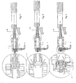
- FIG. 1 represents an exploded view with nomenclature according to the control principle by a striker passing through the piston of the jack according to the invention.
- Figure 2 shows a longitudinal sectional view of the different parts of the cylinder / distributor of Figure 1, as well as a detail view, in the rest position, with the compressed air inlet closed.
- Figure 3 shows a longitudinal sectional view of the different parts of the cylinder / distributor of Figure 1, as well as a detail view, in the activation position of the distributor for opening the air.
- Figure 4 shows a longitudinal sectional view of the different parts of the cylinder / dispenser of Figure 1, and a detail view in the retracted position of the piston, with the open compressed air supply.
- Figure 5 shows a longitudinal sectional view of the various parts of the cylinder / distributor of Figure 1, as well as a detail view, in the piston position out of the cylinder tube, the compressed air inlet being closed.
- FIG. 6 represents a longitudinal sectional view of the various cylinder / distributor parts of FIG. 1, as well as a detailed view, in the return position of the piston of the cylinder moved by its spring, with the escape of the compressed air through the distributor. .
- the device for dispensing automatic compressed air according to the invention can be produced in the form of a kit or integrated into any mechanism such as a rifle or a pistol, in particular for firing simulation or in any mechanism depending on the possibilities of exploiting the advantages. of the invention.
- the initial activation of the dispenser is obtained by percussion of a striker 9 which can slide freely inside a piston 80, by means of a hammer (or dog) 15 which can be an original part of a weapon or device equipped with the automatic compressed air dispenser according to the invention.
- the percussion is done by pivoting forward of the hammer 15 in a recess of the piston body 8.
- FIG. 3 shows the open position of the air inlet.
- a striker 9 which passes through the piston 80 of the cylinder and is controlled by a hammer 15 which strikes the striker 9
- This latter transmits its linear displacement to the valve 5 of the distributor.
- the valve 5 then comes into contact with the distributor seal 3, the latter moving to the left, which allows the compressed air to pass between the attached assembly seal 3 - valve 5 and the piston head 11 of the cylinder .
- the entry of the compressed air into the cylinder 1 has the effect of maintaining, by the pressure of the air which is compressed therein, the assembly 3.5 in the position with a left stop against the distributor support 2, the air inlet 14 remaining open and also effect the integral retraction of the various parts 8,9,10,11 component piston 80 of the cylinder to the right ( Figure 4).
- Figure 5 shows the position of depressurization in the cylinder.
- the latter can either out of the cylinder or cylinder tube 1 or remain in the cylinder through a side air exhaust 12 in the cylinder tube 1. In both cases, this has the effect of reducing the pressure in the cylinder tube 1 and, at the same time, to reduce the pressure on the seal valve assembly 3 and valve 5.
- the assembly 3.5 can then, under the effect of respective springs 4.6 of the two parts 3.5 resume its initial position to the right ( Figure 6), which closes the compressed air supply through the circular double seal of the distributor 3. This also allows the exhaust of the air still in the chamber 10 during the return of the piston 80 of the cylinder which moved by its spring (not shown) returns to its initial rest position to the left.
- the striker portion 9 could be absent and be replaced by direct contact between the piston 80 of the cylinder and the valve 5, which would have the effect that, when closing the cylinder to the left, it would automatically be available all functions illustrated in Figures 3 to 6. To stop in this configuration, the operating cycle, simply interrupt the piston of the cylinder tube before its contact with the valve 5.
- the device of the invention can be made in the form of a kit to be mounted directly in shooting simulation weapons or be adaptable to any other mechanism, either in a kit, or integrated into a more complex set, requiring or not modifications of the device original.
Landscapes
- Engineering & Computer Science (AREA)
- General Engineering & Computer Science (AREA)
- Percussive Tools And Related Accessories (AREA)
- Fluid-Driven Valves (AREA)
- Portable Nailing Machines And Staplers (AREA)
- Toys (AREA)
- Eye Examination Apparatus (AREA)
- Control Of The Air-Fuel Ratio Of Carburetors (AREA)
- Organic Low-Molecular-Weight Compounds And Preparation Thereof (AREA)
Claims (10)
- Automatisch betriebene Vorrichtung zur Verteilung von Druckgas, mit :- einem Zylinder, bestehend aus einer Zylinderbuchse (1), in der sich ein Kolben (80) bewegen kann, der einen Kolbenkopf (11) und ein hinteres Ende besitzt;- einem Verteiler mit einem Verteilerhalter (2), der aus einem vorderen, verschließbaren Ende des besagten Zylinders (1) gebildet wird und einen Druckgaseinlass (14) aufweist;- einer Kammer (13), die ein Druckgas enthalten kann und dynamisch zwischen dem Verteilerträger (2) und dem besagten Kolbenkopf (11) angeordnet ist,dadurch gekennzeichnet, dass die Vorrichtung Mittel umfasst, um die folgenden Vorgänge automatisch nacheinander auszuführen, nachdem das hintere Ende eines Schlagbolzens (9), der im Inneren des Kolbens (80) frei beweglich ist, anfänglich durch einen Hammer (15) angestoßen wurde:- eine Vorwärtsbewegung des Schlagbolzens (9) aus einer anfänglichen Gleichgewichtslage heraus, die den Einlass von Druckgas in die Kammer (13) und einen Druckaufbau in derselben verursacht;- eine Rückwärtsbewegung des Kolbens (80), die das Ausströmen des besagten Druckgases, das sich in der Kammer (13) befindet, verursacht und daher zu einem Druckabfall in dieser Kammer führt;- einen Rückhub des Kolbens (80) in seine Grundstellung, wobei der Druckgaseinlass (14) geschlossen wird und das in der Kammer (13) befindliche Restgas nach vorn entweicht.
- Vorrichtung nach Anspruch 1, dadurch gekennzeichnet, dass sie ein Ventil (5) umfasst, das sich gemäß der Achse des Zylinders (1) öffnen und schließen kann, und eine doppelte Dichtung (3), die das Öffnen und Schließen des Druckgaseinlasses (14) ermöglicht, wobei das Ventil (5) mit einer Rückzugfeder (6) ausgestattet ist, so dass es in der Gleichgewichtslage von der Doppeldichtung (3) auf der Rückseite abgehoben ist; die Doppeldichtung (3) ist mit einer Rückzugfeder (4) versehen, so dass sie in der Gleichgewichtslage den Druckgaseinlass verschließt.
- Vorrichtung nach Anspruch 2, dadurch gekennzeichnet, dass der Kolbenkopf (11) im vorderen Zylinderbereich das Ventil (5) berühren kann, wodurch eine gemeinsame Rückwärtsbewegung des besagten Ventils (5) und der Doppeldichtung (3) bis zum Anschlag am Verteilerhalter (2) verursacht wird; dadurch wird der Einlass des Druckgases durch eine Einlassöffnung (14) in die Kammer (10) verursacht.
- Vorrichtung nach Anspruch 1, dadurch gekennzeichnet, dass beim Druckabfall in der Kammer (10) durch den Rückhub des Kolbens (80) nach hinten das unter Druck stehende Gas durch die Auswärtsbewegung des Kolbens aus dem Zylinder strömt.
- Vorrichtung nach Anspruch 1, dadurch gekennzeichnet, dass beim Druckabfall in der Kammer (10) durch den Rückhub des Kolbens (80) nach hinten das unter Druck stehende Gas durch eine Öffnung (12) im Zylinder (1) ausströmt, wobei der Kolben (80) im Zylinder (1) bleibt.
- Vorrichtung nach Anspruch 1, dadurch gekennzeichnet, dass der Kolben (80) mit einer Rückzugfeder versehen ist, in ihn in seine Gleichgewichtslage im vorderen Zylinderbereich zurückzieht.
- Vorrichtung nach Anspruch 1, dadurch gekennzeichnet, dass das Ventil (5) und die Doppeldichtung (3) sich durch die Wirkung ihrer jeweiligen Rückzugfedern (6, 4) im Gleichgewicht befinden und das Ventil (5) von der Doppeldichtung (3) abgehoben ist, wenn die Kammer nicht oder kaum unter Druck steht und der Kolben (80) das Ventil (5) nicht berührt, wodurch das in der Kammer (10) enthaltene Gas durch eine Öffnung (20) in der Wand des Verteilerhalters (2) entweichen kann, wobei sich die Doppeldichtung (3) in der Stellung befindet, in der sie den Druckgaseinlass (14) verschließt.
- Vorrichtung gemäß einem der Ansprüche 2 bis 7, dadurch gekennzeichnet, dass die Anlaufsteuerung des Verteilers durch den Kontakt zwischen einem vorderen Ende des Schlagbolzens (9) und dem Ventil (5) erfolgt, nachdem der hintere Teil des Schlagbolzens (9) zuerst durch einen Hammer (15) angestoßen wurde.
- Vorrichtung gemäß einem der Ansprüche 2 bis 7, dadurch gekennzeichnet, dass die Anlaufsteuerung des Verteilers durch eine Zugvorrichtung erfolgt, die vor der Einheit angeordnet ist, die aus dem Verteiler und seinem Zylinder gebildet wird.
- Vorrichtung gemäß einem der vorstehenden Ansprüche, dadurch gekennzeichnet, dass das Druckgas Druckluft ist.
Applications Claiming Priority (2)
| Application Number | Priority Date | Filing Date | Title |
|---|---|---|---|
| BE200100598 | 2001-09-14 | ||
| BE2001/0598A BE1014951A4 (fr) | 2001-09-14 | 2001-09-14 | Distributeur d'air comprime a fonctionnement automatique. |
Publications (3)
| Publication Number | Publication Date |
|---|---|
| EP1293746A2 EP1293746A2 (de) | 2003-03-19 |
| EP1293746A3 EP1293746A3 (de) | 2003-03-26 |
| EP1293746B1 true EP1293746B1 (de) | 2006-04-26 |
Family
ID=3897101
Family Applications (1)
| Application Number | Title | Priority Date | Filing Date |
|---|---|---|---|
| EP02447176A Expired - Lifetime EP1293746B1 (de) | 2001-09-14 | 2002-09-13 | Automatischer Druckluftverteiler |
Country Status (5)
| Country | Link |
|---|---|
| US (1) | US6739324B2 (de) |
| EP (1) | EP1293746B1 (de) |
| AT (1) | ATE324566T1 (de) |
| BE (1) | BE1014951A4 (de) |
| DE (1) | DE60210883T2 (de) |
Families Citing this family (6)
| Publication number | Priority date | Publication date | Assignee | Title |
|---|---|---|---|---|
| DE20214533U1 (de) * | 2002-09-19 | 2002-12-05 | J.G. Anschütz GmbH & Co. KG, 89079 Ulm | Gasdruckwaffe |
| DE102004047628B4 (de) * | 2004-09-30 | 2008-09-18 | Heckler & Koch Gmbh | Waffensimulator und Feuerwaffe dafür |
| USD587766S1 (en) | 2006-07-20 | 2009-03-03 | Kee Action Sports I Llc | Paintball field marker |
| US20110041825A1 (en) * | 2009-08-20 | 2011-02-24 | Shih-Che Hu | Gun-lock assembly |
| US9068792B2 (en) * | 2012-08-29 | 2015-06-30 | Real Action Paintball (Rap4) | Projectile launcher able to launch an object using a hammer |
| CZ308759B6 (cs) * | 2020-03-12 | 2021-04-28 | Altaros Air Solutions s.r.o. | Tělo střelné plynové zbraně bez ztrátového expanzního prostoru |
Family Cites Families (13)
| Publication number | Priority date | Publication date | Assignee | Title |
|---|---|---|---|---|
| GB713044A (en) * | 1952-04-15 | 1954-08-04 | Keikki Eino Klemola | Improvements in or relating to air guns or rifles |
| US3612026A (en) * | 1970-03-18 | 1971-10-12 | Crosman Arms Co Inc | Gas-operated revolver with rotatable magazine |
| US4819609A (en) * | 1986-12-22 | 1989-04-11 | Tippmann Dennis J | Automatic feed marking pellet gun |
| US4850330A (en) * | 1987-12-01 | 1989-07-25 | Katsumi Nagayoshi | Device for shooting bullets by pressure medium for use in a toy gun |
| GB2228067B (en) * | 1988-11-30 | 1993-07-21 | Bubb Anthony John Allen | Air discharge valve |
| US4936282A (en) * | 1988-12-09 | 1990-06-26 | Dobbins Jerrold M | Gas powered gun |
| GB2258913A (en) * | 1991-05-17 | 1993-02-24 | Stephen Robert Wilkins | Valve for a pneumatic firearm |
| US5160795A (en) * | 1991-07-29 | 1992-11-03 | Crosman Corporation | Gun with pivoting barrel, rotary ammunition cylinder, and double action firing mechanism |
| US5363834A (en) * | 1993-03-30 | 1994-11-15 | Daisy Manufacturing Company, Inc. | Gun powered by either compressed gas cartridge or hand-pumped air |
| US5349938A (en) * | 1993-04-22 | 1994-09-27 | Farrell Kenneth R | Reciprocatable barrel pneumatic gun |
| US5497758A (en) * | 1994-06-23 | 1996-03-12 | Dobbins; Jerrold M. | Compressed gas powered gun |
| US5613483A (en) * | 1995-11-09 | 1997-03-25 | Lukas; Michael A. | Gas powered gun |
| US5778868A (en) * | 1997-02-03 | 1998-07-14 | K.K.M. Inc. | Pneumatic gun |
-
2001
- 2001-09-14 BE BE2001/0598A patent/BE1014951A4/fr not_active IP Right Cessation
-
2002
- 2002-09-13 EP EP02447176A patent/EP1293746B1/de not_active Expired - Lifetime
- 2002-09-13 DE DE60210883T patent/DE60210883T2/de not_active Expired - Fee Related
- 2002-09-13 AT AT02447176T patent/ATE324566T1/de not_active IP Right Cessation
- 2002-09-13 US US10/243,125 patent/US6739324B2/en not_active Expired - Fee Related
Also Published As
| Publication number | Publication date |
|---|---|
| EP1293746A2 (de) | 2003-03-19 |
| EP1293746A3 (de) | 2003-03-26 |
| BE1014951A4 (fr) | 2004-07-06 |
| DE60210883T2 (de) | 2006-11-09 |
| ATE324566T1 (de) | 2006-05-15 |
| US20030051717A1 (en) | 2003-03-20 |
| DE60210883D1 (de) | 2006-06-01 |
| US6739324B2 (en) | 2004-05-25 |
Similar Documents
| Publication | Publication Date | Title |
|---|---|---|
| EP0324688B1 (de) | Von der Schulter abzufeuernder Raketenwerfer | |
| FR2696536A1 (fr) | Jouets d'action. | |
| CN109716055A (zh) | 预包装虫枪弹匣 | |
| EP0719998A2 (de) | Automatische oder halbautomatische Schusswaffe | |
| US7856969B2 (en) | Air gun | |
| EP1293746B1 (de) | Automatischer Druckluftverteiler | |
| FR2463379A1 (fr) | Arme de tir a air precomprime | |
| FR2685072A1 (fr) | Dispositif pneumatique de recul artificiel pour une arme individuelle. | |
| EP0308321A1 (de) | Gerät zum Befestigen für Unterwasserarbeiten | |
| BE1016438A5 (fr) | Dispositif de tir. | |
| US12078444B2 (en) | Gas projectile platform and assembly | |
| EP1939576B1 (de) | Druckluftwaffe | |
| WO2010029272A1 (fr) | Mecanisme pneumatique pour arme-jouet lancant des billes de peinture ou de plastique de faible poids, actionne par une munition pyrotechnique specifique | |
| FR2806787A1 (fr) | Dispositif chargeur mobile de balles de petit calibre dans une arme a air comprime | |
| FR2847665A1 (fr) | Pistolet a gaz comprime | |
| FR2604247A1 (fr) | Dispositif d'ejection au moyen d'une charge propulsive liquide d'un projectile place dans un tube de lancement. | |
| FR2684438A1 (fr) | Canon utilisant une charge propulsive liquide. | |
| BE519777A (de) | ||
| FR2492082A1 (fr) | Dispositif pneumatique de lancement de projectiles, arme en une seule operation et comportant un systeme anti-recul | |
| FR2681674A1 (fr) | Dispositif de rearmement et arme a air comprime ainsi equipee. | |
| FR3099568A3 (fr) | Structure à mouvement de va-et-vient a verrou pour un pistolet jouet | |
| FR2986611A1 (fr) | Dispositif de lancement pneumatique | |
| JPH07151494A (ja) | エア式、ガス圧力式遊戯銃における弾丸の発射および自動給弾機構 | |
| BE507306A (de) | ||
| FR2713324A1 (fr) | Ensemble de propulsion pour projectile. |
Legal Events
| Date | Code | Title | Description |
|---|---|---|---|
| PUAI | Public reference made under article 153(3) epc to a published international application that has entered the european phase |
Free format text: ORIGINAL CODE: 0009012 |
|
| PUAL | Search report despatched |
Free format text: ORIGINAL CODE: 0009013 |
|
| AK | Designated contracting states |
Kind code of ref document: A2 Designated state(s): AT BE BG CH CY CZ DE DK EE ES FI FR GB GR IE IT LI LU MC NL PT SE SK TR |
|
| AX | Request for extension of the european patent |
Extension state: AL LT LV MK RO SI |
|
| AK | Designated contracting states |
Kind code of ref document: A3 Designated state(s): AT BE BG CH CY CZ DE DK EE ES FI FR GB GR IE IT LI LU MC NL PT SE SK TR |
|
| AX | Request for extension of the european patent |
Extension state: AL LT LV MK RO SI |
|
| 17P | Request for examination filed |
Effective date: 20030730 |
|
| AKX | Designation fees paid |
Designated state(s): AT BE BG CH CY CZ DE DK EE ES FI FR GB GR IE IT LI LU MC NL PT SE SK TR |
|
| 17Q | First examination report despatched |
Effective date: 20040805 |
|
| GRAP | Despatch of communication of intention to grant a patent |
Free format text: ORIGINAL CODE: EPIDOSNIGR1 |
|
| GRAS | Grant fee paid |
Free format text: ORIGINAL CODE: EPIDOSNIGR3 |
|
| GRAA | (expected) grant |
Free format text: ORIGINAL CODE: 0009210 |
|
| AK | Designated contracting states |
Kind code of ref document: B1 Designated state(s): AT BE BG CH CY CZ DE DK EE ES FI FR GB GR IE IT LI LU MC NL PT SE SK TR |
|
| PG25 | Lapsed in a contracting state [announced via postgrant information from national office to epo] |
Ref country code: IT Free format text: LAPSE BECAUSE OF FAILURE TO SUBMIT A TRANSLATION OF THE DESCRIPTION OR TO PAY THE FEE WITHIN THE PRESCRIBED TIME-LIMIT;WARNING: LAPSES OF ITALIAN PATENTS WITH EFFECTIVE DATE BEFORE 2007 MAY HAVE OCCURRED AT ANY TIME BEFORE 2007. THE CORRECT EFFECTIVE DATE MAY BE DIFFERENT FROM THE ONE RECORDED. Effective date: 20060426 Ref country code: CZ Free format text: LAPSE BECAUSE OF FAILURE TO SUBMIT A TRANSLATION OF THE DESCRIPTION OR TO PAY THE FEE WITHIN THE PRESCRIBED TIME-LIMIT Effective date: 20060426 Ref country code: AT Free format text: LAPSE BECAUSE OF FAILURE TO SUBMIT A TRANSLATION OF THE DESCRIPTION OR TO PAY THE FEE WITHIN THE PRESCRIBED TIME-LIMIT Effective date: 20060426 Ref country code: IE Free format text: LAPSE BECAUSE OF FAILURE TO SUBMIT A TRANSLATION OF THE DESCRIPTION OR TO PAY THE FEE WITHIN THE PRESCRIBED TIME-LIMIT Effective date: 20060426 Ref country code: SK Free format text: LAPSE BECAUSE OF FAILURE TO SUBMIT A TRANSLATION OF THE DESCRIPTION OR TO PAY THE FEE WITHIN THE PRESCRIBED TIME-LIMIT Effective date: 20060426 Ref country code: FI Free format text: LAPSE BECAUSE OF FAILURE TO SUBMIT A TRANSLATION OF THE DESCRIPTION OR TO PAY THE FEE WITHIN THE PRESCRIBED TIME-LIMIT Effective date: 20060426 Ref country code: NL Free format text: LAPSE BECAUSE OF FAILURE TO SUBMIT A TRANSLATION OF THE DESCRIPTION OR TO PAY THE FEE WITHIN THE PRESCRIBED TIME-LIMIT Effective date: 20060426 Ref country code: GB Free format text: LAPSE BECAUSE OF FAILURE TO SUBMIT A TRANSLATION OF THE DESCRIPTION OR TO PAY THE FEE WITHIN THE PRESCRIBED TIME-LIMIT Effective date: 20060426 |
|
| REG | Reference to a national code |
Ref country code: GB Ref legal event code: FG4D Free format text: NOT ENGLISH |
|
| REG | Reference to a national code |
Ref country code: IE Ref legal event code: FG4D Free format text: LANGUAGE OF EP DOCUMENT: FRENCH |
|
| REF | Corresponds to: |
Ref document number: 60210883 Country of ref document: DE Date of ref document: 20060601 Kind code of ref document: P |
|
| PG25 | Lapsed in a contracting state [announced via postgrant information from national office to epo] |
Ref country code: SE Free format text: LAPSE BECAUSE OF FAILURE TO SUBMIT A TRANSLATION OF THE DESCRIPTION OR TO PAY THE FEE WITHIN THE PRESCRIBED TIME-LIMIT Effective date: 20060726 Ref country code: DK Free format text: LAPSE BECAUSE OF FAILURE TO SUBMIT A TRANSLATION OF THE DESCRIPTION OR TO PAY THE FEE WITHIN THE PRESCRIBED TIME-LIMIT Effective date: 20060726 |
|
| PG25 | Lapsed in a contracting state [announced via postgrant information from national office to epo] |
Ref country code: ES Free format text: LAPSE BECAUSE OF FAILURE TO SUBMIT A TRANSLATION OF THE DESCRIPTION OR TO PAY THE FEE WITHIN THE PRESCRIBED TIME-LIMIT Effective date: 20060806 |
|
| PG25 | Lapsed in a contracting state [announced via postgrant information from national office to epo] |
Ref country code: PT Free format text: LAPSE BECAUSE OF FAILURE TO SUBMIT A TRANSLATION OF THE DESCRIPTION OR TO PAY THE FEE WITHIN THE PRESCRIBED TIME-LIMIT Effective date: 20060926 |
|
| PG25 | Lapsed in a contracting state [announced via postgrant information from national office to epo] |
Ref country code: MC Free format text: LAPSE BECAUSE OF NON-PAYMENT OF DUE FEES Effective date: 20060930 Ref country code: LI Free format text: LAPSE BECAUSE OF NON-PAYMENT OF DUE FEES Effective date: 20060930 Ref country code: CH Free format text: LAPSE BECAUSE OF NON-PAYMENT OF DUE FEES Effective date: 20060930 |
|
| NLV1 | Nl: lapsed or annulled due to failure to fulfill the requirements of art. 29p and 29m of the patents act | ||
| REG | Reference to a national code |
Ref country code: IE Ref legal event code: FD4D |
|
| GBV | Gb: ep patent (uk) treated as always having been void in accordance with gb section 77(7)/1977 [no translation filed] |
Effective date: 20060426 |
|
| PLBE | No opposition filed within time limit |
Free format text: ORIGINAL CODE: 0009261 |
|
| STAA | Information on the status of an ep patent application or granted ep patent |
Free format text: STATUS: NO OPPOSITION FILED WITHIN TIME LIMIT |
|
| 26N | No opposition filed |
Effective date: 20070129 |
|
| REG | Reference to a national code |
Ref country code: CH Ref legal event code: PL |
|
| PG25 | Lapsed in a contracting state [announced via postgrant information from national office to epo] |
Ref country code: GR Free format text: LAPSE BECAUSE OF FAILURE TO SUBMIT A TRANSLATION OF THE DESCRIPTION OR TO PAY THE FEE WITHIN THE PRESCRIBED TIME-LIMIT Effective date: 20060727 |
|
| PG25 | Lapsed in a contracting state [announced via postgrant information from national office to epo] |
Ref country code: BG Free format text: LAPSE BECAUSE OF FAILURE TO SUBMIT A TRANSLATION OF THE DESCRIPTION OR TO PAY THE FEE WITHIN THE PRESCRIBED TIME-LIMIT Effective date: 20060726 Ref country code: EE Free format text: LAPSE BECAUSE OF FAILURE TO SUBMIT A TRANSLATION OF THE DESCRIPTION OR TO PAY THE FEE WITHIN THE PRESCRIBED TIME-LIMIT Effective date: 20060426 |
|
| PG25 | Lapsed in a contracting state [announced via postgrant information from national office to epo] |
Ref country code: TR Free format text: LAPSE BECAUSE OF FAILURE TO SUBMIT A TRANSLATION OF THE DESCRIPTION OR TO PAY THE FEE WITHIN THE PRESCRIBED TIME-LIMIT Effective date: 20060426 Ref country code: LU Free format text: LAPSE BECAUSE OF NON-PAYMENT OF DUE FEES Effective date: 20060913 |
|
| PG25 | Lapsed in a contracting state [announced via postgrant information from national office to epo] |
Ref country code: CY Free format text: LAPSE BECAUSE OF FAILURE TO SUBMIT A TRANSLATION OF THE DESCRIPTION OR TO PAY THE FEE WITHIN THE PRESCRIBED TIME-LIMIT Effective date: 20060426 |
|
| PGFP | Annual fee paid to national office [announced via postgrant information from national office to epo] |
Ref country code: DE Payment date: 20081002 Year of fee payment: 7 |
|
| PGFP | Annual fee paid to national office [announced via postgrant information from national office to epo] |
Ref country code: BE Payment date: 20080829 Year of fee payment: 7 |
|
| PGFP | Annual fee paid to national office [announced via postgrant information from national office to epo] |
Ref country code: FR Payment date: 20080929 Year of fee payment: 7 |
|
| BERE | Be: lapsed |
Owner name: *RDIH Effective date: 20090930 |
|
| REG | Reference to a national code |
Ref country code: FR Ref legal event code: ST Effective date: 20100531 |
|
| PG25 | Lapsed in a contracting state [announced via postgrant information from national office to epo] |
Ref country code: DE Free format text: LAPSE BECAUSE OF NON-PAYMENT OF DUE FEES Effective date: 20100401 Ref country code: FR Free format text: LAPSE BECAUSE OF NON-PAYMENT OF DUE FEES Effective date: 20090930 |
|
| PG25 | Lapsed in a contracting state [announced via postgrant information from national office to epo] |
Ref country code: BE Free format text: LAPSE BECAUSE OF NON-PAYMENT OF DUE FEES Effective date: 20090930 |