EP1293816A2 - Appareil de microscopie chirurgicale - Google Patents
Appareil de microscopie chirurgicale Download PDFInfo
- Publication number
- EP1293816A2 EP1293816A2 EP02014252A EP02014252A EP1293816A2 EP 1293816 A2 EP1293816 A2 EP 1293816A2 EP 02014252 A EP02014252 A EP 02014252A EP 02014252 A EP02014252 A EP 02014252A EP 1293816 A2 EP1293816 A2 EP 1293816A2
- Authority
- EP
- European Patent Office
- Prior art keywords
- image
- surgical
- displayed
- microscope system
- surgical microscope
- Prior art date
- Legal status (The legal status is an assumption and is not a legal conclusion. Google has not performed a legal analysis and makes no representation as to the accuracy of the status listed.)
- Withdrawn
Links
Images


Classifications
-
- G—PHYSICS
- G02—OPTICS
- G02B—OPTICAL ELEMENTS, SYSTEMS OR APPARATUS
- G02B21/00—Microscopes
- G02B21/0004—Microscopes specially adapted for specific applications
- G02B21/0012—Surgical microscopes
Definitions
- the present invention relates to a surgical microscope system.
- the present invention relates to a surgical microscope system preferably used in neurosurgery or the like.
- a typical surgical microscope includes a pair of eyepieces to be used by a surgeon.
- a primary object of the present invention is to provide a surgical microscope system capable of reducing the burdens on surgeons and surgical assistants.
- a surgical microscope system comprises: an objective lens on which reflected light from an imaging part is incident; a spectrogram distributes luminous flux from the objective lens into tow directions; photoelectric imaging means provided on each distributed sides of the luminous flux; an image processing apparatus for generating image signals in response to imaging signals from each photoelectric imaging means and alternately outputting the image signals; image displaying means for alternately displaying images in response to the respective image signals; and a stereoscope generator for impressing the displayed image according to one of the image signals on one of eyes while impressing the displayed image according to the other of the image signals on the other of eyes.
- a plurality of the image displaying means may be included, where the orientation of the image to be displayed by at least one of the image displaying means may be variable.
- the image processing apparatus may include: a reference image generation portion for generating a basis image signal in response to the imaging signal from each of the photoelectric imaging means and displaying the basis image on the image displaying means; and an invert image generation portion for generating an inverted image signal provided as an inversion of the basis image in the vertical or horizontal direction in response to the imaging signal.
- the image displaying means for each of the surgeon and the surgical assistant can be previously prepared even though the imaging part is viewed from the different direction by each of the surgeon and the surgical assistant.
- the image to be displayed can be inverted to a predetermined direction.
- the surgeon and the surgical assistant are allowed to view the image in the same direction as that of viewing the imaging part by the surgeon and the surgical assistant.
- prompt surgical procedures can be performed.
- the image processing apparatus may include a masking portion for displaying a predetermined part being imaged among the images displayed on the image forming means.
- the image processing apparatus may include a fader for adjusting a light intensity of an image to be displayed by the image displaying means.
- the fader regulates the light intensity to prevent the image on the CRT display from being excessively brightened. Therefore, the displayed image is prevented from halation, so that the surgeon can be allowed to perform surgical procedures without difficulty.
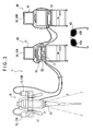
- Fig. 1 shows a general view of a principal configuration of the surgical microscope system 1 of the present embodiment.
- Fig. 2 shows a graphical representation of neurosurgery using the surgical microscope system 1 by a surgeon X and a surgical assistant Y facing to each other.
- the surgical microscope system 1 comprises a microscope body 10, an image processing apparatus 20, image-displaying means (i.e., two CRT displays) 30 (30A, 30B), and a three-dimensional image formation means 40.
- the microscope body 10 comprises: an objective lens 11 directing to an imaging part (i.e., a surgical field), on which reflected light P from the imaging part can be incident; a spectrogram 12 that bends the reflected light P from the imaging part to 90 degrees and then distributes the reflected light P in two directions; and two CCD cameras 13 (13A, 13B) as electro-optic imaging means on which each luminous flux distributed by the spectrogram 12 can be incident.
- an imaging part i.e., a surgical field
- a spectrogram 12 that bends the reflected light P from the imaging part to 90 degrees and then distributes the reflected light P in two directions
- two CCD cameras 13 13A, 13B
- the objective lens 11 may be a general objective lens to be used in a typical surgical microscope. Especially, it may be an objective lens being constructed so as to irradiate illumination L on the imaging part.
- the spectrogram 12 may be, for example, a pair of zoom lenses (not shown in the figure) arranged in parallel on the light output side of the objective lens 11.
- Each of the zoom lenses is constructed by including a beam splitter or the like arranged on the light output side of the light output side. In this case, furthermore, the zoom lens has an automatic focus facility.
- the CCD camera 13 is not limited to a specific one. In this embodiment, however, the CCD camera 13 is one characterized by the following features. That is, the number of CCD pixels is 41 x 30,000 pixels, the signal system is the NTSC color television system, and an imaging element is 1/3" color CCD, and a horizontal resolution of 750 TV (composite VIDEO).
- the image processing apparatus 20 is capable of generating a high-speed image signal in response to an output signal from each of CCD cameras 13A, 13B and switching between image signals from the respective CCD cameras 13A, 13B, followed by the output of image signals to a CRT display 30 to display the desired images on the screens thereof.
- Such a processing may be performed by an appropriate image-processing program (software) or a built-in high-scan converter.
- the image processing apparatus 20 has an output terminal to output image signals to a video cartridge recorder (VCR) or the like for recording images displayed on the CRT display 30 on a video tape as it is.
- VCR video cartridge recorder
- the CRT display 30 used in this embodiment may be one typically used in the art. According to the present invention, however, means for displaying an image is not limited to such a CRT display 30. Alternatively, a liquid crystal display, a projector, or any image-displaying means can be used.
- one of the CRT displays 30 is a CRT display 30B provided for the surgical assistant Y and is mounted on a turntable stand 31.
- the turntable stand 31 comprises an external cylindrical part 33 fixed on a column 32 and an internal cylindrical part 34 housed in the external cylindrical part 33, where the internal cylindrical part 34 is allowed to turn in the circumferential direction.
- the CRT display 30B is housed and fixed in the internal cylindrical part 34.
- the turntable stand 31 it becomes possible to rotate the CRT display 30B against the CRT display 30A used by the surgeon X to any angle, for example 90 degrees or 180 degrees in any direction, so that the orientation of the display can be adjusted.
- the stereoscope generator 40 comprises a liquid crystal polarizing apparatus 41 mounted on the front of the screen of the CRT display 30, a driver unit 42 for driving and controlling the liquid crystal polarizing apparatus 41, and circular polarization eyeglasses 43 to be used by each of the surgeon X and the surgical assistant Y.
- the driver unit 42 changes the polarizing direction of the liquid crystal polarizing apparatus 41 in synchronization with the switching of images displayed on the CRT display 30.
- the polarizing direction of the liquid crystal polarizing apparatus 41 is brought into line with the polarizing direction of the polarizing plate 43A corresponding to, for example, a left-eyed portion of the circular polarization eyeglasses 43 for making a visual identification only by the left eye.
- the polarizing direction of the liquid crystal polarizing apparatus 41 is brought into line with the polarizing direction of the polarizing plate 43B corresponding to a right-eyed portion of the circular polarization eyeglasses 43. Consequently, an image on the CRT display 30 can be viewed as a three-dimensional image.
- the surgical microscope system 2 is constructed just as in the case of the first preferred embodiment except of the follows. In this embodiment, that is, the configuration of the image processing apparatus is different from that of the first preferred embodiment and there is no turntable stand.
- the surgical microscope system 2 comprises a microscope body 10, an image processing apparatus 50, two CRT displays 30 (30A, 30B) as means for displaying an image, and stereoscope generator 40.
- the microscope body 10, the CRT displays 30, and the stereoscope generator 40 are same as those shown in the first preferred embodiment. Therefore, their explanations will be omitted.
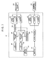
- the image processing apparatus 50 generates basis image signals in response to output signals from the CCD cameras 13A, 13B at a high speed, respectively. Then, each of the basis image signals are processed in a predetermined manner. Subsequently, the processed image signals are alternately outputted to the CRT displays 30 to display an appropriate image on each of the CRT displays 30.
- Such an image processing apparatus comprises a processor 51 having a reference image generator portion as a processing program, and an image inverter 52 having an invert image generator portion as another processing program.
- the image processing apparatus 50 having the processor 51 and the image inverter 52 also includes an output terminal to a video tape recorder or the like just as in the case of the image processing apparatus 20 of the first preferred embodiment, so that an image displayed on the CRT display 30 can be recorded on a video tape.
- the processor 51 of the image processing apparatus 50 generates basis image signals in response to output signals from the CCD cameras 13A, 13B, respectively, at a high speed.
- the basis image signals are alternately outputted to the CRT display 30.
- Such a processor 51 comprises a signal generating portion 511, a fader 512, a masking portion 513, and a signal output portion 514.
- the signal generating portion 511 generates basis image signals in response to output signals from the CCD cameras 13A, 13B, respectively, at a high speed.
- the fader 512 is responsible for automatically regulating input basis image signals before displaying an image on the CRT display 30 such that the light intensity of the image to be displayed on the CRT display 30 is equal to or less than a predetermined light intensity.
- the masking portion 513 processes the basis image signal such that any regions except a predetermined region, for example any regions except an affected part A as a field of operation, can be changed to black on the CRT display so that the surgeon OP or the like cannot recognize it.
- the masking portion 513 only permits the display of the affected part A. Therefore, the image displayed on the CRT display 30 as shown in Fig. 6(A) (represented as XYZ coordinates) is converted into one colored with a most dark color to prevent that the surgeon OP observes such a color.
- the signal output portion 514 outputs basis image signals to the main CRT display 30A one after the other.
- the basis image signal corresponding to the CCD cameras 13A and 14A is generated from the signal generating portion 511 and, it is passed through the fader 512 and the masking portion 513.
- the signal output portion 514 outputs similar basis image signals alternately to the image inverter 52.
- the image inverter 52 has a function of reversing an image on the sub CRT display 30B such that an image displayed on the sub CRT display 30B can be one provided as a invert image of the reference image displayed on the CRT display 30A in the X direction (lateral direction) and the Y direction (vertical direction) as shown in Fig. 4 by converting basis image signals inputted from signal emission portion 514.
- the image inverter 52 has an X-directed converter 521 for reversing the image in the X direction and a Y-directed converter 522 for reversing the image in the Y direction.
- image information on a look-up table is subjected to an invert operation in response to a center axis passing through the center of the image in the Y direction.
- the process of reversing in the Y direction can be performed by the same way as that of the Y direction conversion 522. Therefore, the image displayed on the sub CRT display 30B can be provided as an inverted image obtained by reversing a reference image in each of the X and Y directions.
- an image invert operation in the image inverter 52 can be implemented by a circuit shown in Fig. 7. That is, the basis image signals 100 inputted from the respective CCD cameras 13A 13B are temporally stored in a video buffer 101, a Y buffer 102 as a predetermined standard luminance signal, and a C buffer 103 as a predetermined color-difference signal, respectively.
- the synchronized signals are outputted to an unclamp circuit 106 through a video/Y circuit 105.
- the unclamp circuit 106 amplifies the signal and an A/D converter 107 converts the amplified signal into a digital signal.
- the synchronizer 104 brings the color-difference signal into sync with the previously synchronized signal in the C buffer 103.
- the unclamp circuit 108 amplifies the synchronized signal and an A/D converter 109 converts the amplified signal into a digital signal.
- digital signals for the respective three primitive colors are formed by the digital decoder 110.
- the digital RGB signals are subjected to an inversion process in the inverter 111 using a lookup table.
- the digital RGB signals are reconverted into analog RGB signals by a digital encoder 112.
- these analog RGB signals are temporally stored in a video driver 113, a Y driver 114, and a C driver 115.
- the inverted image signals 120 are outputted to the CRT display 30(30B), respectively.
- Fig. 8 is a schematic diagram for illustrating the positions of a surgeon and a surgical assistant at the time of performing surgical procedures on the brain.
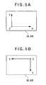
- Fig. 9 is a schematic diagram for illustrating an image displayed on each of CRT displays 30 during the surgical procedures in Fig. 8.
- Fig. 10 is a schematic diagram for illustrating the positions of the surgeon and the surgical assistant who performs surgical procedures on a spinal cord.
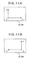
- Fig. 11 is a schematic diagram for illustrating an image displayed on each of CRT displays 30 during the surgical procedures in Fig. 10.
- a predetermined cover 62 having an opening to exposure an affected part A as a field of operation of a patient P is placed on the patient P on a surgical bed 61.
- a surgeon OP is positioned across the affected part A of the patient P from a surgical assistant AS so that the surgeon OP and the surgical assistant AS face to each other.
- main CRT display 30A for the surgeon OP and the sub CRT display 30B for the surgical assistant AS are arranged in the respective positions that allow them to easily view the screens of the respective displays 30A, 30B.
- the microscope body 10 is set out such that is objective lens 11 is positioned above the affected part A.
- the microscope body 10 except the objective lens 11 and its surrounding portions is covered with a predetermined covering member (not shown) to prevent the microscope body 10 from undesired effects of the leakage of luminous flux and disturbing light from the outside.
- images shown in Fig. 9(A) and Fig. 9(B) can be displayed on the respective CRT displays 30A, 30B.
- the image displayed on the CRT display 30B for the surgical assistant AS shown in Fig. 9(B) is one obtained by reversing the image displayed on the CRT display 30A for the surgeon OR in the X and Y directions by operating both the X direction converter 521 and the Y direction converter 522 of the image inverter 52 such that the affected part A can be provided as an image viewed from the surgical assistant AS.
- each of the surgeon OR and the surgical assistant AS are allowed to view the images displayed on the CRT displays 30 as respective three-dimensional images to give the impression of solidity.
- the patient P on the surgical bed 61 is covered with a cover 62 with an opening for only exposing a spinal cord region as an affected part A.
- a surgeon OP is positioned across the affected part A of the patient P from a surgical assistant AS so that the surgeon OP and the surgical assistant AS face to each other.
- the main CRT display 30A for the surgeon OP and the sub CRT display 30B for the surgical assistant AS are arranged in the respective positions that allow them to directly view the screens of the respective displays 30A, 30B without any difficulty.
- the microscope body 10 is set out such that its objective lens 11 is positioned above the affected part A.
- the surgical microscope system 2 when the surgical microscope system 2 is actuated, images shown in Fig. 11(A) and Fig. 11(B) can be displayed on the respective CRT displays 30A, 30B.
- the image displayed on the CRT display 30B for the surgical assistant AS is one obtained by reversing the image displayed on the CRT display 30A for the surgeon OR in the X direction by operating the X direction converter 521 of the image inverter 52 such that the affected part A can be provided as an image viewed from the surgical assistant AS.
- each of the surgeon OR and the surgical assistant AS are allowed to view the images displayed on the CRT displays 30 with a three-dimensional image formation means 40 as respective three-dimensional images to give the impression of solidity.
- the imaging part is displayed on each of the CRT displays 30A, 30B such that the image directly represents a view from the surgeon OP.
- the imaging part can be displayed on the CRT display 30B for the surgical assistant AS such that the image directly represents a view from the surgical assistant AS by inverting the image to be displayed on the CRT display 30B. Therefore, the image to be displayed on the CRT display 30B for the surgical assistant AS may be appropriately inverted when the surgeon OP and the surgical assistant AS facing to each other cooperatively perform the surgical procedures. Therefore, there is no possibility that the surgical assistant AS mistakes for vertical and horizontal directions of the image on the CRT display, compared with the conventional system in which the CRT display 30A for the surgeon OP is only provided. In other words, the assistant surgeon SA does not require reconfiguration of the operating direction or the like in the image so as to correspond to the standing position of the assistant surgeon SA, resulting in prompt operation.
- the surgical microscope system of the present embodiment is constructed such that only a predetermined surgical field such as an affected part A comes into view of each of the surgeon OP and the surgical assistant AS. Therefore, the surgeon OP and so on may only focus clearly on the affected part A by a masking portion 513. Therefore, even though long hour's surgical procedures, the possibility of causing eye fatigue can be further decreased and burdensome to the surgeon OP or the like can be reduced.
- the fader 512 regulates the light intensity to prevent the image on the CRT display 30 from being excessively brightened. Therefore, the displayed image is prevented from halation, so that the surgeon OP can be allowed to perform surgical procedures without difficulty.
- the present invention is not limited to each of the above-preferred embodiments. It will be appreciated by a person skilled in the art that other configurations of the surgical microscope system or the like that attain the objects of the present invention can be included in the present invention. For example, the following modifications may be included in the present invention.
- the eyepieces are not provided in the microscope body 10.
- eyepieces may be preliminarily included in the microscope body 10 (i.e., it is not always used).
- the spectrogram of the present invention is not limited to the configuration of the spectrogram 12 in each of the preferred embodiments. Any configuration may be allowed while satisfying the functions of the spectrogram.
- the direction of displaying the imaging part on the CRT display 30B supported by the turntable stand 31 can be changed by turning the CRT display 30B.
- an image processing program or the like to be used in the image processing apparatus 20 may be designed to change the direction of the imaging part to be displayed by the CRT display 30B.
- the image processing apparatus 50 is provided independently from the processor 51 and the image inverter 52.
- a signal converter in the image inverter 52 may be integrally incorporated in the processor 51.
- any mechanism is not particularly mounted.
- a zoom portion for displaying an enlarged view of the affected part A may be additionally included in the processor 51 to facilitate the recognition of the affected part A. Therefore, there is an advantage of performing surgical procedures more easily.
Landscapes
- Physics & Mathematics (AREA)
- Health & Medical Sciences (AREA)
- General Health & Medical Sciences (AREA)
- Surgery (AREA)
- Chemical & Material Sciences (AREA)
- Analytical Chemistry (AREA)
- General Physics & Mathematics (AREA)
- Optics & Photonics (AREA)
- Microscoopes, Condenser (AREA)
Applications Claiming Priority (2)
| Application Number | Priority Date | Filing Date | Title |
|---|---|---|---|
| JP2001282326 | 2001-09-17 | ||
| JP2001282326A JP2002272760A (ja) | 2001-01-09 | 2001-09-17 | 手術用顕微鏡システム |
Publications (2)
| Publication Number | Publication Date |
|---|---|
| EP1293816A2 true EP1293816A2 (fr) | 2003-03-19 |
| EP1293816A3 EP1293816A3 (fr) | 2004-11-10 |
Family
ID=19105991
Family Applications (1)
| Application Number | Title | Priority Date | Filing Date |
|---|---|---|---|
| EP02014252A Withdrawn EP1293816A3 (fr) | 2001-09-17 | 2002-06-26 | Appareil de microscopie chirurgicale |
Country Status (2)
| Country | Link |
|---|---|
| US (1) | US20030053202A1 (fr) |
| EP (1) | EP1293816A3 (fr) |
Cited By (3)
| Publication number | Priority date | Publication date | Assignee | Title |
|---|---|---|---|---|
| EP1925962A1 (fr) * | 2006-11-21 | 2008-05-28 | Swiss Medical Technology GmbH | Système de microscope vidéo stéréo |
| WO2008061738A1 (fr) | 2006-11-21 | 2008-05-29 | Swiss Medical Technology Gmbh | Système de microscope stéréo vidéo |
| EP2136232A1 (fr) * | 2008-06-18 | 2009-12-23 | Kabushiki Kaisha TOPCON | Appareil microscope vidéo stéréo binoculaire |
Families Citing this family (4)
| Publication number | Priority date | Publication date | Assignee | Title |
|---|---|---|---|---|
| US10499994B2 (en) | 2014-02-27 | 2019-12-10 | University Surgical Associates, Inc. | Interactive display for surgery with mother and daughter video feeds |
| US10898290B2 (en) | 2015-06-26 | 2021-01-26 | Sony Olympus Medical Solutions Inc. | Surgical microscope device and surgical microscope system |
| JP2018063309A (ja) * | 2016-10-11 | 2018-04-19 | カイロス株式会社 | 顕微鏡装置 |
| CN112190348A (zh) * | 2020-09-23 | 2021-01-08 | 苏州速迈医疗设备有限公司 | 一种双人手术显微镜 |
Family Cites Families (5)
| Publication number | Priority date | Publication date | Assignee | Title |
|---|---|---|---|---|
| US4987488A (en) * | 1988-03-07 | 1991-01-22 | George Berci | Video system for visualizing microsurgical images with enhanced depth of field |
| US5867210A (en) * | 1996-02-09 | 1999-02-02 | Rod; Samuel R. | Stereoscopic on-screen surgical microscope systems |
| JP4266409B2 (ja) * | 1998-09-09 | 2009-05-20 | オリンパス株式会社 | 手術用顕微鏡 |
| US6144762A (en) * | 1998-02-23 | 2000-11-07 | Olympus America Inc. | Stereo video microscope |
| JP4477174B2 (ja) * | 1999-11-19 | 2010-06-09 | オリンパス株式会社 | 被検体観察装置 |
-
2002
- 2002-06-25 US US10/179,450 patent/US20030053202A1/en not_active Abandoned
- 2002-06-26 EP EP02014252A patent/EP1293816A3/fr not_active Withdrawn
Cited By (4)
| Publication number | Priority date | Publication date | Assignee | Title |
|---|---|---|---|---|
| EP1925962A1 (fr) * | 2006-11-21 | 2008-05-28 | Swiss Medical Technology GmbH | Système de microscope vidéo stéréo |
| WO2008061738A1 (fr) | 2006-11-21 | 2008-05-29 | Swiss Medical Technology Gmbh | Système de microscope stéréo vidéo |
| US8791995B2 (en) | 2006-11-21 | 2014-07-29 | Swiss Medical Technology Gmbh | Stereo video microscope system |
| EP2136232A1 (fr) * | 2008-06-18 | 2009-12-23 | Kabushiki Kaisha TOPCON | Appareil microscope vidéo stéréo binoculaire |
Also Published As
| Publication number | Publication date |
|---|---|
| EP1293816A3 (fr) | 2004-11-10 |
| US20030053202A1 (en) | 2003-03-20 |
Similar Documents
| Publication | Publication Date | Title |
|---|---|---|
| JP2607828B2 (ja) | ハイディフィニションテレビ統合顕微鏡システム | |
| US5751341A (en) | Stereoscopic endoscope system | |
| EP2903551B1 (fr) | Système numérique pour la capture et l'affichage d'une vidéo chirurgicale | |
| JP3625906B2 (ja) | 手術用顕微鏡装置 | |
| CN109863755B (zh) | 信号处理设备、方法和程序 | |
| US4987488A (en) | Video system for visualizing microsurgical images with enhanced depth of field | |
| JP2002207169A (ja) | 光学的観察装置 | |
| JPH07261094A (ja) | 手術用顕微鏡 | |
| JP4802806B2 (ja) | 画像表示装置 | |
| EP1293816A2 (fr) | Appareil de microscopie chirurgicale | |
| JPH0662438A (ja) | 立体像観察システム | |
| JP2004024835A (ja) | 手術用顕微鏡 | |
| JP2002267935A (ja) | 光学的観察装置の重畳補足情報の明るさ制御装置 | |
| WO1994028783A1 (fr) | Systeme d'endoscope video medical | |
| JPH05107482A (ja) | 手術用顕微鏡 | |
| WO1998013716A1 (fr) | Systeme d'information optique in situ | |
| JP3386082B2 (ja) | 撮影装置におけるビューファインダー | |
| JP3860871B2 (ja) | 内視鏡装置 | |
| JP3205552B2 (ja) | 立体映像撮像装置 | |
| JP2002272760A (ja) | 手術用顕微鏡システム | |
| JPH07311361A (ja) | 眼球投影型映像表示装置 | |
| JP2002287079A (ja) | 映像付与装置 | |
| JP3809267B2 (ja) | 眼科撮影装置 | |
| JPH0876027A (ja) | 立体内視鏡撮像装置 | |
| JP3140813B2 (ja) | 内視鏡テレビシステム |
Legal Events
| Date | Code | Title | Description |
|---|---|---|---|
| PUAI | Public reference made under article 153(3) epc to a published international application that has entered the european phase |
Free format text: ORIGINAL CODE: 0009012 |
|
| AK | Designated contracting states |
Kind code of ref document: A2 Designated state(s): AT BE CH CY DE DK ES FI FR GB GR IE IT LI LU MC NL PT SE TR Designated state(s): AT BE CH CY DE DK ES FI FR GB GR IE IT LI LU MC NL PT SE TR |
|
| AX | Request for extension of the european patent |
Extension state: AL LT LV MK RO SI |
|
| PUAL | Search report despatched |
Free format text: ORIGINAL CODE: 0009013 |
|
| AK | Designated contracting states |
Kind code of ref document: A3 Designated state(s): AT BE CH CY DE DK ES FI FR GB GR IE IT LI LU MC NL PT SE TR |
|
| AX | Request for extension of the european patent |
Extension state: AL LT LV MK RO SI |
|
| RIC1 | Information provided on ipc code assigned before grant |
Ipc: 7G 02B 21/36 B Ipc: 7G 02B 21/22 B Ipc: 7G 02B 21/06 B Ipc: 7G 02B 21/00 A |
|
| STAA | Information on the status of an ep patent application or granted ep patent |
Free format text: STATUS: THE APPLICATION IS DEEMED TO BE WITHDRAWN |
|
| 18D | Application deemed to be withdrawn |
Effective date: 20050104 |