EP1293995B1 - Induktives elektronisches Bauelement in Flachbauweise, insbesondere Planartransformator oder Planarspule - Google Patents
Induktives elektronisches Bauelement in Flachbauweise, insbesondere Planartransformator oder Planarspule Download PDFInfo
- Publication number
- EP1293995B1 EP1293995B1 EP02020299A EP02020299A EP1293995B1 EP 1293995 B1 EP1293995 B1 EP 1293995B1 EP 02020299 A EP02020299 A EP 02020299A EP 02020299 A EP02020299 A EP 02020299A EP 1293995 B1 EP1293995 B1 EP 1293995B1
- Authority
- EP
- European Patent Office
- Prior art keywords
- winding
- winding elements
- insulating
- electronic component
- inductive electronic
- Prior art date
- Legal status (The legal status is an assumption and is not a legal conclusion. Google has not performed a legal analysis and makes no representation as to the accuracy of the status listed.)
- Expired - Lifetime
Links
Images


Classifications
-
- H—ELECTRICITY
- H01—ELECTRIC ELEMENTS
- H01F—MAGNETS; INDUCTANCES; TRANSFORMERS; SELECTION OF MATERIALS FOR THEIR MAGNETIC PROPERTIES
- H01F27/00—Details of transformers or inductances, in general
- H01F27/28—Coils; Windings; Conductive connections
- H01F27/32—Insulating of coils, windings, or parts thereof
- H01F27/323—Insulation between winding turns, between winding layers
-
- H—ELECTRICITY
- H01—ELECTRIC ELEMENTS
- H01F—MAGNETS; INDUCTANCES; TRANSFORMERS; SELECTION OF MATERIALS FOR THEIR MAGNETIC PROPERTIES
- H01F27/00—Details of transformers or inductances, in general
- H01F27/28—Coils; Windings; Conductive connections
- H01F27/2847—Sheets; Strips
-
- H—ELECTRICITY
- H01—ELECTRIC ELEMENTS
- H01F—MAGNETS; INDUCTANCES; TRANSFORMERS; SELECTION OF MATERIALS FOR THEIR MAGNETIC PROPERTIES
- H01F27/00—Details of transformers or inductances, in general
- H01F27/28—Coils; Windings; Conductive connections
- H01F27/32—Insulating of coils, windings, or parts thereof
- H01F27/324—Insulation between coil and core, between different winding sections, around the coil; Other insulation structures
-
- H—ELECTRICITY
- H01—ELECTRIC ELEMENTS
- H01F—MAGNETS; INDUCTANCES; TRANSFORMERS; SELECTION OF MATERIALS FOR THEIR MAGNETIC PROPERTIES
- H01F19/00—Fixed transformers or mutual inductances of the signal type
-
- H—ELECTRICITY
- H01—ELECTRIC ELEMENTS
- H01F—MAGNETS; INDUCTANCES; TRANSFORMERS; SELECTION OF MATERIALS FOR THEIR MAGNETIC PROPERTIES
- H01F27/00—Details of transformers or inductances, in general
- H01F27/28—Coils; Windings; Conductive connections
- H01F27/2804—Printed windings
-
- H—ELECTRICITY
- H01—ELECTRIC ELEMENTS
- H01F—MAGNETS; INDUCTANCES; TRANSFORMERS; SELECTION OF MATERIALS FOR THEIR MAGNETIC PROPERTIES
- H01F5/00—Coils
- H01F5/06—Insulation of windings
Definitions
- the invention relates to an inductive electronic component in planar design, in particular a planar transformer or a planar coil, with a winding package having one or more planar windings, wherein the windings are each formed of superimposed, flat and conductive, separated by insulating films, winding elements, which are arranged around a winding core.
- the winding elements in planar transformers and coils are insulated on top of each other, wherein the windings associated with the individual windings are connected in series connection in an electrically conductive manner.
- the winding elements each comprise two electrical connections.
- transformers which usually have a primary winding and at least one secondary winding, the terminals of the primary and secondary windings are each made opposite.
- An insulation between the winding elements is realized by applied on both sides of the winding elements insulation films made of plastic. The insulating films are connected to one another such that the electrically conductive parts of the winding elements are completely surrounded by insulating material.
- Transformers and coils of this type are used, for example, in switched-mode power supplies and operated at switching frequencies of a few tens to a few hundred kilohertz. Due to the high switching frequencies can the number of winding elements and the size of the transformer or the coil are kept small.
- the clearance and creepage distances as well as the insulation thicknesses depend on the rated voltage. For example, at a rated voltage of 300 volts for safe separation between the winding elements and the winding elements and the core air gaps of 5.5 mm and creepage distances of 6 mm must be observed.
- the insulation thickness between the individual winding elements must be 1.0 mm for a solid insulation and 0.3 mm for a multi-layer (3-layer) insulation.
- transformers therefore comprise winding elements of an insulating film, are applied to the electrically conductive tracks. At least one of the windings is guided in a closed housing to comply with the prescribed creepage distances. In addition, the conductor tracks are arranged at a sufficient distance from the edge of the insulating films.
- This type of insulation is e.g. in EP-B-0 542 445.
- the disadvantage here is that due to the housing and the distance of the tracks to the edge of the film actually available for the strip conductors winding window width can not be fully utilized.
- the object of the invention is to provide an inductive electronic component in planar design, in particular a planar transformer or a planar coil of the type mentioned, with an insulation system that meets the prescribed safety requirements and allows a compact design of the transformer or the coil at high power density ,
- the edges of the winding elements are at least partially or completely beaded with an insulating adhesive film or the winding elements are substantially completely surrounded by an insulating adhesive film.
- the insulation films are dimensioned together with the beadings / wrappings matched to one another that the prescribed by the relevant safety authorities isolation, air and creepage distances are met.
- the dimensions of the insulating films in partial areas correspond to the dimensions of the winding elements and go beyond the dimensions of the winding elements in the remaining partial areas, that is to say that they project beyond the outer edges of the winding elements in these partial areas.
- the insulating films may be made of any suitable insulating material, preferably plastics, such as polyester, PEN, polyamide, Nomex, are used. The choice of insulation material depends on the Component requirements (temperature resistance, UL approval, price, etc.).
- the advantage of the invention lies in the fact that the prescribed isolation criteria are met, without the need for special bobbins, which ensure the insulation. Furthermore, the existing winding window width can be fully utilized.
- the outer edges of the subregions of the winding elements, on which the insulating film does not project, are flanged according to the invention with an insulating adhesive film.
- the corresponding subregions of the winding elements can also be completely surrounded by adhesive film.
- adhesive tapes are used: polyester adhesive tape, PEN tape (Kaladex 2000), polyimide tape (Kapton). These are standard insulation tapes used in transformer and coil construction.
- the insulation films can be constructed in one layer as well as consist of several individual film layers. Several layers have the advantage that the total necessary insulation thickness is reduced.
- the winding elements are designed as substantially rectangular or oval, open conductor loops, each with two long legs and two short legs.
- the insulating films are particularly in the field of short legs beyond the outer dimensions of the winding elements and there ensure compliance with the insulation and creepage distances.
- the winding package is wrapped in the region of the long legs of the winding elements with a plurality of layers of an insulating film.
- the winding elements preferably consist of conductor plates, in particular of copper sheet.
- the winding elements can also consist of a flat insulator with an applied conductive layer.
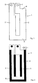
- Figure 1 shows a view of a typical winding element, which preferably consists of a copper sheet.
- the winding element 1 is formed substantially as a rectangular or oval conductor loop and has two, approximately parallel to each other long legs 2, 3 and two mutually parallel short legs 4, 5.
- each winding element 1 terminals 6, 7 For contacting with other winding elements, each winding element 1 terminals 6, 7 , When stacking a plurality of winding elements, these terminals 6, 7 come to lie exactly above each other and allow easy contacting of the winding elements 1 with each other. The connections of the other winding are made opposite.
- FIG. 2 shows that in particular the outer and inner edges of the long legs 2, 3 of the winding element 1 are glued or beaded over with an adhesive film 8.
- the lower edge of the short leg 5 is also beaded with the adhesive film 8.
- an insulating film 9 is introduced, as shown in Figure 3.
- the insulation film corresponds in shape approximately to the winding elements 1.
- the regions 10 of the insulation film 9 are approximately as wide as the long legs 2, 3 of the winding elements 1, wherein the regions 11, however, are wider or longer and, in particular Area of the short legs 4, 5, beyond the outer edges of the winding elements 1 protrude.
- FIG. 4 shows a winding element 1 which is beaded with adhesive tape 8 and which is placed on an insulating film 9. It can be seen clearly that the insulation film 9 z. B. at the edges 12, 13 and 14 of the winding element 1 projects beyond these edges by a distance s. This supernatant forms in turn, the prescribed creepage distance of 2 xs between two superimposed winding elements 1.
- the winding core 15, which consists of two, in cross-section approximately E-shaped, core halves, is inserted between the consisting of several winding elements 1 winding package, so that two legs of the core left and right of the long legs 2, 3 of the winding package come to rest and the middle leg of the core 15 is located in the interior of the winding package. Due to the projection of the insulating film 9 at the edges 12 and 14 of the winding element 1, a corresponding insulation distance of 1 xs to the core 15 and 2 xs between the winding elements 1 is ensured.
- FIG. 5 shows a cross section through a long leg 2 of the finished winding package.
- the winding elements 1 are beaded at their outer edges with an adhesive film 8.
- the insulating films 9 have a certain thickness d to ensure the prescribed insulation distance between the respective winding elements 1.
- FIG. 6 shows an assembly aid 17 for mounting the winding package.
- the mounting aid consists of a flat base plate and a plurality of mounting mandrels 18 to 20 standing vertically upwards from the base plate.
- the inner mounting mandrels 18 are arranged in such a way that they engage in the interior of the winding elements 1 or the insulating foils 9.
- the mounting mandrels 19 are arranged so that they engage in the solder holes of the terminals 6, 7 of the winding elements 1 and thus ensure further positional alignment of the winding elements.
- the mounting spikes 20 serve to align winding elements 1 with differently shaped terminals and solder holes.
- FIG. 7 shows a plan view of a transformer according to the invention, wherein the upper half of the winding core 15 is not shown for the sake of clarity.
- the winding core 21 surrounding the winding core 15 comprises oppositely led out terminals 22, 23 for the respective primary and secondary windings.
Landscapes
- Engineering & Computer Science (AREA)
- Power Engineering (AREA)
- Coils Of Transformers For General Uses (AREA)
- Coils Or Transformers For Communication (AREA)
- Insulating Of Coils (AREA)
Description
- Die Erfindung betrifft ein induktives elektronisches Bauelement in Planarbauweise, insbesondere einen Planartransformator oder eine Planarspule, mit einem Wicklungspaket, welches eine oder mehrere planare Wicklungen aufweist, wobei die Wicklungen jeweils aus übereinander liegenden, flachen und leitfähigen, durch Isolationsfolien voneinander getrennten, Wicklungselementen gebildet sind, welche um einen Wicklungskern angeordnet werden.
- Die Wicklungselemente bei planaren Transformatoren und Spulen liegen isoliert übereinander, wobei die den einzelnen Wicklungen zugeordneten Wicklungselemente in Serienschaltung elektrisch leitend miteinander verbunden sind. Hierzu umfassen die Wicklungselemente jeweils zwei elektrische Anschlüsse. Bei Transformatoren, die in der Regel eine Primärwicklung und mindestens eine Sekundärwicklung aufweisen, werden die Anschlüsse der Primär- und Sekundärwicklungen jeweils gegenüberliegend ausgeführt.
Ein derartiger Transformator ist in der EP 0 608 127 A1 offenbart. Eine Isolation zwischen den Wicklungselementen wird durch beidseitig auf die Wicklungselemente aufgebrachte Isolationsfolien aus Kunststoff realisiert. Die Isolationsfolien werden derart miteinander verbunden, dass die elektrisch leitenden Teile der Wicklungselemente vollständig mit Isolationsmaterial umgeben sind. - Transformatoren und Spulen dieser Bauart werden zum Beispiel in Schaltnetzteilen verwendet und bei Schaltfrequenzen von einigen zehn bis einigen hundert Kilohertz betrieben. Durch die hohen Schaltfrequenzen können die Anzahl der Wicklungselemente und die Baugröße des Transformators bzw. der Spule klein gehalten werden.
- Insbesondere wenn hohe Spannungen verwendet werden, ist es bei der geringen Baugröße eines Planartransformators bzw. Planarspule wichtig, die von den jeweils zuständigen Sicherheitsbehörden, wie z.B. V.D.E. (Deutschland), U.L. (USA), C.S.A (Kanada), vorgeschriebenen Sicherheitskriterien betreffend die minimalen Luft- und Kriechstrecken sowie Isolationsdicken zwischen den einzelnen Wicklungselementen und dem Kern einzuhalten.
- Die Luft- und Kriechstrecken sowie die Isolationsdicken sind abhängig von der Bemessungsspannung. Beispielsweise sind bei einer Bemessungsspannung von 300 Volt für eine sichere Trennung zwischen den Wicklungselementen sowie den Wicklungselementen und dem Kern Luftstrecken von 5,5 mm und Kriechstrecken von 6 mm einzuhalten. Die Isolationsdicke zwischen den einzelnen Wicklungselementen muss je nach Anwendung bei einer festen Isolation 1,0 mm und bei einer mehrlagigen (3-lagigen) Isolation insgesamt 0,3 mm betragen.
- Bekannte Transformatoren umfassen daher Wicklungselemente aus einer isolierenden Folie, auf die elektrisch leitende Bahnen aufgebracht sind. Mindestens eine der Wicklungen wird in einem geschlossenen Gehäuse geführt, um die vorgeschriebenen Kriechstrecken einzuhalten. Zusätzlich werden die Leiterbahnen in einem ausreichenden Abstand zum Rand der isolierenden Folien angeordnet. Diese Art der Isolation ist z.B. in der EP-B-0 542 445 offenbart. Nachteilig hierbei ist, dass aufgrund des Gehäuses und dem Abstand der Leiterbahnen zur Folienkante die für die Leiterbahnen eigentlich zur Verfügung stehende Wickelfensterbreite nicht vollständig ausgenutzt werden kann.
- Eine andere Möglichkeit zur Einhaltung der Isolations- und Kriechstrecken sieht vor, spezielle Spulenkörper mit Isolationskammern zu verwenden, in welchen die Wicklungselemente aufgenommen sind. Dies ist in den Schriften EP-B-0 476 114 oder der EP-A-0 933 789 gezeigt. Bei dieser Lösung müssen spezielle Spulenkörper hergestellt werden, was höhere Kosten nach sich zieht. Zudem ist keine starke Verschachtelung der Wicklungselemente möglich, was zu Lasten der Baugröße geht.
- Die Aufgabe der Erfindung besteht darin, ein induktives elektronisches Bauelement in Planarbauweise, insbesondere einen Planartransformator oder eine Planarspule der eingangs genannten Art, mit einem Isolationssystem zu versehen, das die vorgeschriebenen Sicherheitsanforderungen erfüllt und eine kompakte Bauweise des Transformators bzw. der Spule bei hoher Leistungsdichte zulässt.
- Diese Aufgabe wird durch die im Patentanspruch 1 angegebenen Merkmale gelöst.
- Erfindungsgemäß ist vorgesehen, dass die Kanten der Wicklungselemente mindestens teilweise oder vollständig mit einer isolierenden Klebefolie umbördelt sind oder die Wicklungselemente im Wesentlichen vollständig mit einer isolierenden Klebefolie umgeben sind. Ferner sind die Isolationsfolien zusammen mit den Umbördelungen /Einwicklungen derart aufeinander abgestimmt dimensioniert, dass die von den zuständigen Sicherheitsbehörden vorgeschriebenen Isolations-, Luft- und Kriechstrecken eingehalten werden. Dabei entsprechen die Abmessungen der Isolationsfolien in Teilbereichen den Abmessungen der Wicklungselemente und gehen in den übrigen Teilbereichen über die Abmessungen der Wicklungselemente hinaus, d.h., sie stehen in diesen Teilbereichen über die Außenkanten der Wicklungselemente über.
- Hierbei ist der Begriff "Folie" nicht beschränkend anzusehen. Die Isolationsfolien können aus jedem geeigneten Isolationsmaterial gefertigt sein, wobei vorzugsweise Kunststoffe, wie z.B. Polyester, PEN, Polyamid, Nomex, eingesetzt werden. Die Wahl des Isolationsmaterials richtet sich nach den Anforderungen des Bauteils (Temperaturbeständigkeit, UL-Zulassung, Preis, etc.).
- Der Vorteil der Erfindung ist darin zu sehen, dass die vorgeschriebenen Isolationskriterien erfüllt werden, ohne dass spezielle Spulenkörper notwendig sind, welche die Isolation sicherstellen. Ferner kann die vorhandene Wickelfensterbreite voll ausgenutzt werden.
- Zudem kann mit einer relativ dünnen Isolation gearbeitet werden, so dass eine hohe Verschachtelungstiefe und eine minimale Streuinduktivität erreicht wird und außerdem Stromverdrängungseffekte, insbesondere Skin- und Proximityeffekt, minimiert werden.
- Durch diese überstehenden Kanten der Isolationsfolie werden die benötigten Isolationsstrecken und Kriechstrecken in den entsprechenden Teilbereichen der Wicklungselemente sichergestellt.
- Die Außenkanten der Teilbereiche der Wicklungselemente, an denen die Isolationsfolie nicht übersteht, werden erfindungsgemäß mit einer isolierenden Klebefolie umbördelt. Die entsprechenden Teilbereiche der Wicklungselemente können auch ganz mit Klebefolie umgeben werden. Zum Umbördeln der Wicklungselemente können z.B. folgende Klebebänder verwendet werden: Polyesterklebeband, PEN-Klebeband (Kaladex 2000), Polyimidklebeband (Kapton). Es handelt sich dabei um gängige, im Transformatoren- und Spulenbau verwendete Isolationsklebebänder.
- Die Isolationsfolien können sowohl einlagig aufgebaut sein als auch aus mehreren einzelnen Folienlagen bestehen. Mehrere Lagen haben den Vorteil, dass sich die insgesamt notwendige Isolationsdicke verringert.
- Die Wicklungselemente sind als im Wesentlichen rechteckige oder ovale, offene Leiterschleifen ausgebildet, mit jeweils zwei langen Schenkeln und zwei kurzen Schenkeln. Die Isolationsfolien stehen insbesondere im Bereich der kurzen Schenkel über die Außenabmessungen der Wicklungselemente hinaus und sorgen dort für die Einhaltung der Isolations- und Kriechstrecken.
- Da zwischen den Kanten der Wicklungselemente und dem Kern nur eine relativ dünne Isolierung vorhanden ist, kann in einer bevorzugten Ausgestaltung der Erfindung vorgesehen sein, dass das Wicklungspaket im Bereich der langen Schenkel der Wicklungselemente mit mehreren Lagen einer Isolationsfolie umwickelt ist.
- Die Wicklungselemente bestehen vorzugsweise aus Leitungsblechen, insbesondere aus Kupferblech. Die Wicklungselemente können aber auch aus einem flachen Isolator mit einer aufgebrachten leitfähigen Schicht bestehen.
- Ein Ausführungsbeispiel der Erfindung wird nun anhand der Zeichnungsfiguren beschrieben. Es kann sich dabei sowohl um einen Transformator als auch eine Spule handeln, da deren Aufbau sich grundsätzlich nicht wesentlich voneinander unterscheidet. Aus den Zeichnungen und deren Beschreibung ergeben sich weitere Merkmale, Vorteile und Ausgestaltungen der Erfindung.
- Es zeigen:
- Figur 1:
- eine Draufsicht auf ein Wicklungselement des Wickelkörpers;
- Figur 2:
- ein Wicklungselement gemäß Figur 1 mit umbördelten (abgeklebten) Kanten;
- Figur 3:
- eine Draufsicht auf eine Isolationsfolie;
- Figur 4:
- ein auf eine Isolationsfolie aufgelegtes Wicklungselement mit umbördelten Kanten und eingelegtem Ferritkern;
- Figur 5:
- einen Querschnitt durch einen langen Schenkel eines fertigen Wicklungspakets;
- Figur 6:
- eine Draufsicht auf eine Montagehilfe zur Montage des Wicklungspakets mit eingelegter Isolationsfolie;
- Figur 7:
- den Aufbau eines planaren Transformators gemäß der Erfindung in einer Aufsicht.
- Figur 1 zeigt eine Ansicht eines typischen Wicklungselementes, welches vorzugsweise aus einem Kupferblech besteht. Das Wicklungselement 1 ist im Wesentlichen als rechteckige oder ovale Leiterschleife ausgebildet und besitzt jeweils zwei, in etwa zueinander parallele lange Schenkel 2, 3 und zwei zueinander parallele kurze Schenkel 4, 5. Zur Kontaktierung mit weiteren Wicklungselementen weist jedes Wicklungselement 1 Anschlüsse 6, 7 auf. Beim Übereinanderstapeln mehrerer Wicklungselemente kommen diese Anschlüsse 6, 7 genau übereinander zu liegen und erlauben eine einfache Kontaktierung der Wicklungselemente 1 untereinander. Die Anschlüsse der anderen Wicklung werden gegenüber ausgeführt.
- In Figur 2 ist dargestellt, dass insbesondere die Außen- und Innenkanten der langen Schenkel 2, 3 des Wicklungselementes 1 mit einer Klebefolie 8 umklebt bzw. umbördelt sind. Die untere Kante des kurzen Schenkels 5 ist ebenfalls mit der Klebefolie 8 umbördelt. Diese Umbördelung um den Betrag s stellt die vorgeschriebene Kriechstrecke zwischen zwei aufeinander liegenden Wicklungselementen 1 sicher, wobei die Kriechstrecke zwei mal dem Betrag s entspricht. Die Kriechstrecke zum Wicklungskern entspricht dem Betrag s.
- Zwischen zwei aufeinander liegenden Wicklungselementen 1 wird erfindungsgemäß eine Isolationsfolie 9 eingebracht, wie sie in Figur 3 dargestellt ist. Die Isolationsfolie entspricht in ihrer Formgebung in etwa den Wicklungselementen 1. Die Bereiche 10 der Isolationsfolie 9 sind in etwa so breit ausgebildet wie die langen Schenkel 2, 3 der Wicklungselemente 1, wobei die Bereiche 11 jedoch breiter bzw. länger ausgebildet sind und, insbesondere im Bereich der kurzen Schenkel 4, 5, über die Außenkanten der Wicklungselemente 1 hinausstehen.
- Figur 4 zeigt ein mit Klebeband 8 umbördeltes Wicklungselement 1, welches auf eine Isolationsfolie 9 aufgelegt ist. Man erkennt deutlich, dass die Isolationsfolie 9 z. B. an den Kanten 12, 13 und 14 des Wicklungselementes 1 über diese Kanten um eine Strecke s hinaussteht. Dieser Überstand bildet wiederum die vorgeschriebene Kriechstrecke von 2 x s zwischen zwei aufeinander liegenden Wicklungselementen 1. Der Wicklungskern 15, der aus zwei, im Querschnitt etwa E-förmigen, Kernhälften besteht, wird zwischen das aus mehreren Wicklungselementen 1 bestehende Wicklungspaket eingeführt, so dass zwei Schenkel des Kerns links und rechts der langen Schenkel 2, 3 des Wicklungspaketes zu liegen kommen und der mittlere Schenkel des Kerns 15 im Innenraum des Wicklungspaketes liegt. Durch den Überstand der Isolationsfolie 9 an den Kanten 12 und 14 des Wicklungselementes 1 wird ein entsprechender Isolationsabstand von 1 x s zum Kern 15 und 2 x s zwischen den Wicklungselementen 1 sichergestellt.
- Figur 5 zeigt einen Querschnitt durch einen langen Schenkel 2 des fertigen Wicklungspaketes. Man erkennt die übereinander liegenden Wicklungselemente 1, zwischen denen jeweils eine Isolationsfolie 9 angeordnet ist. Die Wicklungselemente 1 sind an ihren Außenkanten mit einer Klebefolie 8 umbördelt. Die Isolationsfolien 9 weisen eine bestimmte Dicke d auf, um den vorgeschriebenen Isolationsabstand zwischen den jeweiligen Wicklungselementen 1 sicherzustellen. An den Außenkanten der Wicklungselemente 1 wirkt nur die umbördelte Klebefolie 8 als Isolation. Aus diesem Grunde werden die Außenschenkel des Wicklungspaketes zusätzlich mit mehreren Lagen einer Isolationsfolie 16 umwickelt.
- In Figur 6 ist schließlich eine Montagehilfe 17 zur Montage des Wicklungspaketes dargestellt. Die Montagehilfe besteht aus einer flachen Grundplatte und mehreren, von der Grundplatte senkrecht nach oben stehenden Montagedornen 18 bis 20. Die inneren Montagedorne 18 sind derart angeordnet, dass sie in den Innenraum der Wicklungselemente 1 bzw. der Isolationsfolien 9 eingreifen. Dadurch werden die übereinander liegenden Lagen von Wicklungselementen 1 und Isolationsfolien gegenseitig ausgerichtet. Die Montagedorne 19 sind so angeordnet, dass sie in die Lötbohrungen der Anschlüsse 6, 7 der Wicklungselemente 1 eingreifen und sorgen somit für eine weitere lagengenaue Ausrichtung der Wicklungselemente. Die Montagedorne 20 dienen zur Ausrichtung von Wicklungselementen 1 mit anders gestalteten Anschlüssen und Lötbohrungen.
- Figur 7 zeigt schließlich eine Aufsicht auf einen erfindungsgemäßen Transformator, wobei die obere Hälfte des Wicklungskerns 15 der Übersicht halber nicht dargestellt ist. Das den Wicklungskern 15 umgebende Wicklungspaket 21 umfasst gegenüberliegend herausgeführte Anschlüsse 22, 23 für die jeweiligen Primär- und Sekundärwicklungen.
-
- 1
- Wicklungselement
- 2
- Schenkel, lang
- 3
- Schenkel, lang
- 4
- Schenkel, kurz
- 5
- Schenkel, kurz
- 6
- Anschluss
- 7
- Anschluss
- 8
- Umbördelung
- 9
- Isolationsfolie
- 10
- Bereich
- 11
- Bereich
- 12
- Kante
- 13
- Kante
- 14
- Kante
- 15
- Wicklungskern
- 16
- Isolationsfolie
- 17
- Montagehilfe
- 18
- Dorn
- 19
- Dorn
- 20
- Dorn
- 21
- Wicklungspaket
- 22
- Anschlüsse
- 23
- Anschlüsse
Claims (8)
- Induktives elektronisches Bauelement in Planarbauweise, insbesondere Planartransformator oder Planarspule, mit einem Wicklungspaket, bestehend aus einer oder mehreren planaren Wicklungen, die jeweils aus übereinander liegenden, flachen und leitfähigen, durch Isolationsfolien (9) voneinander getrennten, Wicklungselementen (1) gebildet sind, welche um einen Wicklungskern (15) angeordnet werden, dadurch gekennzeichnet, dass die Kanten der Wicklungselemente (1) mindestens teilweise oder vollständig mit einer isolierenden Klebefolie (8) umbördelt sind oder die Wicklungselemente (1) im Wesentlichen vollständig mit einer isolierenden Klebefolie (8) umgeben sind, und dass die Isolationsfolien (9) zusammen mit den Umbördelungen/Einwicklungen der Wicklungselemente (1) mit Klebefolie (8) derart aufeinander abgestimmt dimensioniert sind, dass die von den zuständigen Sicherheitsbehörden vorgeschriebenen Isolations-, Luft- und Kriechstrecken (d; s) eingehalten werden, wobei die Abmessungen der Isolationsfolien (9) in Teilbereichen (10) den Abmessungen der Wicklungselemente (1) entsprechen und in den übrigen Teilbereichen (11) über die Abmessungen der Wicklungselemente hinausgehen.
- Induktives elektronisches Bauelement nach einem der Ansprüche 1, dadurch gekennzeichnet, dass die den erstgenannten Teilbereichen (10) zugeordneten Kanten der Wicklungselemente (1) mit einer isolierenden Klebefolie (8) umbördelt sind.
- Induktives elektronisches Bauelement nach einem der Ansprüche 1 oder 2, dadurch gekennzeichnet, dass jede Isolationsfolie (9) aus mehreren einzelnen Folienlagen besteht.
- Induktives elektronisches Bauelement nach einem der Ansprüche 1 bis 3, dadurch gekennzeichnet, dass die Wicklungselemente (1) als im Wesentlichen rechteckige oder ovale, offene Leiterschleifen ausgebildet sind, mit jeweils zwei langen Schenkeln (2, 3) und zwei kurzen Schenkeln (4, 5).
- Induktives elektronisches Bauelement nach einem der Ansprüche 1 bis 4, dadurch gekennzeichnet, dass die Isolationsfolien (9) überwiegend im Bereich der kurzen Schenkel (4, 5) über die Außenabmessungen der Wicklungselemente (1) hinausstehen.
- Induktives elektronisches Bauelement nach einem der Ansprüche 1 bis 5, dadurch gekennzeichnet, dass das Wicklungspaket im Bereich der langen Schenkel (2, 3) der Wicklungselemente (1) mit mehreren Lagen einer Isolationsfolie (16) umwickelt ist.
- Induktives elektronisches Bauelement nach einem der Ansprüche 1 bis 6, dadurch gekennzeichnet, dass die Wicklungselemente (1) aus Leitungsblechen bestehen.
- Induktives elektronisches Bauelement nach einem der Ansprüche 1 bis 7, dadurch gekennzeichnet, dass die Wicklungselemente (1) aus einem Isolator mit einer aufgebrachten leitfähigen Schicht bestehen.
Applications Claiming Priority (2)
| Application Number | Priority Date | Filing Date | Title |
|---|---|---|---|
| DE10145278A DE10145278A1 (de) | 2001-09-14 | 2001-09-14 | Induktives elektronisches Bauelement in Flachbauweise insbesondere Planartransformator oder Planarspule |
| DE10145278 | 2001-09-14 |
Publications (3)
| Publication Number | Publication Date |
|---|---|
| EP1293995A2 EP1293995A2 (de) | 2003-03-19 |
| EP1293995A3 EP1293995A3 (de) | 2003-04-16 |
| EP1293995B1 true EP1293995B1 (de) | 2006-06-14 |
Family
ID=7698994
Family Applications (1)
| Application Number | Title | Priority Date | Filing Date |
|---|---|---|---|
| EP02020299A Expired - Lifetime EP1293995B1 (de) | 2001-09-14 | 2002-09-11 | Induktives elektronisches Bauelement in Flachbauweise, insbesondere Planartransformator oder Planarspule |
Country Status (7)
| Country | Link |
|---|---|
| EP (1) | EP1293995B1 (de) |
| AT (1) | ATE330322T1 (de) |
| CY (1) | CY1105203T1 (de) |
| DE (2) | DE10145278A1 (de) |
| DK (1) | DK1293995T3 (de) |
| ES (1) | ES2266372T3 (de) |
| PT (1) | PT1293995E (de) |
Families Citing this family (3)
| Publication number | Priority date | Publication date | Assignee | Title |
|---|---|---|---|---|
| US8054154B2 (en) * | 2008-09-26 | 2011-11-08 | Linclon Global, Inc. | Planar transformer and method of manufacturing |
| EP2400511A1 (de) * | 2010-06-28 | 2011-12-28 | ABB Technology AG | Modulare unrunde Spule für Transformatoren |
| US9620278B2 (en) | 2014-02-19 | 2017-04-11 | General Electric Company | System and method for reducing partial discharge in high voltage planar transformers |
Family Cites Families (9)
| Publication number | Priority date | Publication date | Assignee | Title |
|---|---|---|---|---|
| JPS6379307A (ja) * | 1986-09-22 | 1988-04-09 | Murata Mfg Co Ltd | 積層トランス |
| JPH04250605A (ja) * | 1991-01-10 | 1992-09-07 | Toshiba Corp | 箔巻変圧器 |
| JPH06151179A (ja) * | 1992-11-02 | 1994-05-31 | Murata Mfg Co Ltd | コイル |
| EP0608127A1 (de) * | 1993-01-22 | 1994-07-27 | AT&T Corp. | Isolierungsanordnung für Magnetwindungen mit gestapelten flachen Leitern |
| AT1045U1 (de) * | 1995-10-03 | 1996-09-25 | Fronius Schweissmasch | Spulenkörper und verfahren zu dessen herstellung für einen transformator |
| DE19615921A1 (de) * | 1996-04-22 | 1997-10-23 | Vacuumschmelze Gmbh | Induktives Bauelement in flacher Bauform |
| DE19805914A1 (de) * | 1998-02-13 | 1999-08-19 | Thomson Brandt Gmbh | Transformator |
| DE19834615A1 (de) * | 1998-07-31 | 2000-02-03 | Thomson Brandt Gmbh | Transformator |
| US6087922A (en) * | 1998-03-04 | 2000-07-11 | Astec International Limited | Folded foil transformer construction |
-
2001
- 2001-09-14 DE DE10145278A patent/DE10145278A1/de not_active Withdrawn
-
2002
- 2002-09-11 PT PT02020299T patent/PT1293995E/pt unknown
- 2002-09-11 DK DK02020299T patent/DK1293995T3/da active
- 2002-09-11 DE DE50207174T patent/DE50207174D1/de not_active Expired - Lifetime
- 2002-09-11 EP EP02020299A patent/EP1293995B1/de not_active Expired - Lifetime
- 2002-09-11 ES ES02020299T patent/ES2266372T3/es not_active Expired - Lifetime
- 2002-09-11 AT AT02020299T patent/ATE330322T1/de not_active IP Right Cessation
-
2006
- 2006-09-12 CY CY20061101298T patent/CY1105203T1/el unknown
Also Published As
| Publication number | Publication date |
|---|---|
| EP1293995A3 (de) | 2003-04-16 |
| CY1105203T1 (el) | 2010-03-03 |
| DK1293995T3 (da) | 2006-10-16 |
| EP1293995A2 (de) | 2003-03-19 |
| DE50207174D1 (de) | 2006-07-27 |
| ES2266372T3 (es) | 2007-03-01 |
| ATE330322T1 (de) | 2006-07-15 |
| PT1293995E (pt) | 2006-11-30 |
| DE10145278A1 (de) | 2003-04-10 |
Similar Documents
| Publication | Publication Date | Title |
|---|---|---|
| DE4241689C2 (de) | Aufwärts- (Hochspannungs-)Transformator | |
| DE2656050A1 (de) | Transformator | |
| DE102004025076B4 (de) | Spulenanordnung und Verfahren zu deren Herstellung | |
| DE102018115654A1 (de) | Aktiv gekühlte Spule | |
| DE3700488A1 (de) | Leistungsuebertrager mit ferromagnetischem kern | |
| WO2016193017A1 (de) | Planar-transformator zur energieübertragung | |
| DE102018220415A1 (de) | Transformator, Gleichspannungswandler und elektrischer Kraftwagen | |
| DE60130572T2 (de) | Induktive bauelemente | |
| EP3169891B1 (de) | Wicklungsschema für einen transformator eines hochsetzstellers und zündsystem zur versorgung einer funkenstrecke einer brennkraftmaschine mit elektrischer energie | |
| DE9114783U1 (de) | Flachform-Planar-Transformator zur Verwendung in Offline-Schaltnetzteilen | |
| EP1293995B1 (de) | Induktives elektronisches Bauelement in Flachbauweise, insbesondere Planartransformator oder Planarspule | |
| EP0750785B1 (de) | Planartransformator für schaltnetzteile zur erzeugung von kleinspannungen und verfahren zu dessen herstellung | |
| DE4137776C2 (de) | Hochfrequenzleistungsübertrager in Multilayer-Technik | |
| DE3605629C2 (de) | ||
| DE29611276U1 (de) | Planartransformator | |
| EP0479966B1 (de) | Induktives schaltungselement für leiterplattenmontage | |
| EP0240737B1 (de) | Vorschaltdrossel, insbesondere für Gasentladungslampen | |
| DE9213190U1 (de) | Transformator oder Drossel | |
| DE102016219788B4 (de) | Verfahren zur Herstellung eines Leiterplattenstromwandlers | |
| DE102004008961B4 (de) | Spulenkörper für geschlossenen magnetischen Kern und daraus hergestellte Entstördrossel | |
| DE69214094T2 (de) | Flacher Transformator | |
| DE3039549A1 (de) | Elektrischer uebertrager | |
| DE102004053547B4 (de) | Blechschnitt für einen geschichteten Kern eines Transformators | |
| DE19959732A1 (de) | Induktive Vorrichtung | |
| EP0667030B1 (de) | Transformator |
Legal Events
| Date | Code | Title | Description |
|---|---|---|---|
| PUAI | Public reference made under article 153(3) epc to a published international application that has entered the european phase |
Free format text: ORIGINAL CODE: 0009012 |
|
| PUAL | Search report despatched |
Free format text: ORIGINAL CODE: 0009013 |
|
| AK | Designated contracting states |
Kind code of ref document: A2 Designated state(s): AT BE BG CH CY CZ DE DK EE ES FI FR GB GR IE IT LI LU MC NL PT SE SK TR Designated state(s): AT BE BG CH CY CZ DE DK EE ES FI FR GB GR IE IT LI LU MC NL PT SE SK TR |
|
| AX | Request for extension of the european patent |
Extension state: AL LT LV MK RO SI |
|
| AK | Designated contracting states |
Designated state(s): AT BE BG CH CY CZ DE DK EE ES FI FR GB GR IE IT LI LU MC NL PT SE SK TR |
|
| AX | Request for extension of the european patent |
Extension state: AL LT LV MK RO SI |
|
| RIC1 | Information provided on ipc code assigned before grant |
Ipc: 7H 01F 27/32 A Ipc: 7H 01F 27/28 B |
|
| 17P | Request for examination filed |
Effective date: 20030508 |
|
| AKX | Designation fees paid |
Designated state(s): AT BE BG CH CY CZ DE DK EE ES FI FR GB GR IE IT LI LU MC NL PT SE SK TR |
|
| 17Q | First examination report despatched |
Effective date: 20050630 |
|
| GRAP | Despatch of communication of intention to grant a patent |
Free format text: ORIGINAL CODE: EPIDOSNIGR1 |
|
| GRAS | Grant fee paid |
Free format text: ORIGINAL CODE: EPIDOSNIGR3 |
|
| RIN1 | Information on inventor provided before grant (corrected) |
Inventor name: GULDEN, CHRISTOF |
|
| GRAA | (expected) grant |
Free format text: ORIGINAL CODE: 0009210 |
|
| AK | Designated contracting states |
Kind code of ref document: B1 Designated state(s): AT BE BG CH CY CZ DE DK EE ES FI FR GB GR IE IT LI LU MC NL PT SE SK TR |
|
| REG | Reference to a national code |
Ref country code: GB Ref legal event code: FG4D Free format text: NOT ENGLISH |
|
| REG | Reference to a national code |
Ref country code: CH Ref legal event code: EP |
|
| REG | Reference to a national code |
Ref country code: IE Ref legal event code: FG4D Free format text: LANGUAGE OF EP DOCUMENT: GERMAN |
|
| REF | Corresponds to: |
Ref document number: 50207174 Country of ref document: DE Date of ref document: 20060727 Kind code of ref document: P |
|
| PGFP | Annual fee paid to national office [announced via postgrant information from national office to epo] |
Ref country code: CY Payment date: 20060905 Year of fee payment: 5 |
|
| PGFP | Annual fee paid to national office [announced via postgrant information from national office to epo] |
Ref country code: SK Payment date: 20060908 Year of fee payment: 5 Ref country code: TR Payment date: 20060908 Year of fee payment: 5 |
|
| PGFP | Annual fee paid to national office [announced via postgrant information from national office to epo] |
Ref country code: FI Payment date: 20060912 Year of fee payment: 5 |
|
| PGFP | Annual fee paid to national office [announced via postgrant information from national office to epo] |
Ref country code: IE Payment date: 20060913 Year of fee payment: 5 |
|
| PGFP | Annual fee paid to national office [announced via postgrant information from national office to epo] |
Ref country code: EE Payment date: 20060914 Year of fee payment: 5 Ref country code: MC Payment date: 20060914 Year of fee payment: 5 |
|
| PGFP | Annual fee paid to national office [announced via postgrant information from national office to epo] |
Ref country code: ES Payment date: 20060918 Year of fee payment: 5 |
|
| PGFP | Annual fee paid to national office [announced via postgrant information from national office to epo] |
Ref country code: DK Payment date: 20060922 Year of fee payment: 5 |
|
| PGFP | Annual fee paid to national office [announced via postgrant information from national office to epo] |
Ref country code: LU Payment date: 20060925 Year of fee payment: 5 |
|
| PGFP | Annual fee paid to national office [announced via postgrant information from national office to epo] |
Ref country code: NL Payment date: 20060927 Year of fee payment: 5 |
|
| REG | Reference to a national code |
Ref country code: CH Ref legal event code: NV Representative=s name: LUCHS & PARTNER PATENTANWAELTE |
|
| PGFP | Annual fee paid to national office [announced via postgrant information from national office to epo] |
Ref country code: AT Payment date: 20060930 Year of fee payment: 5 |
|
| PGFP | Annual fee paid to national office [announced via postgrant information from national office to epo] |
Ref country code: GR Payment date: 20061002 Year of fee payment: 5 |
|
| REG | Reference to a national code |
Ref country code: SE Ref legal event code: TRGR |
|
| REG | Reference to a national code |
Ref country code: DK Ref legal event code: T3 |
|
| PGFP | Annual fee paid to national office [announced via postgrant information from national office to epo] |
Ref country code: PT Payment date: 20061017 Year of fee payment: 5 |
|
| REG | Reference to a national code |
Ref country code: GR Ref legal event code: EP Ref document number: 20060403146 Country of ref document: GR |
|
| PGFP | Annual fee paid to national office [announced via postgrant information from national office to epo] |
Ref country code: BE Payment date: 20061108 Year of fee payment: 5 |
|
| REG | Reference to a national code |
Ref country code: PT Ref legal event code: SC4A Free format text: AVAILABILITY OF NATIONAL TRANSLATION Effective date: 20060913 |
|
| GBT | Gb: translation of ep patent filed (gb section 77(6)(a)/1977) |
Effective date: 20061116 |
|
| ET | Fr: translation filed | ||
| REG | Reference to a national code |
Ref country code: EE Ref legal event code: FG4A Ref document number: E000843 Country of ref document: EE Effective date: 20060914 |
|
| REG | Reference to a national code |
Ref country code: ES Ref legal event code: FG2A Ref document number: 2266372 Country of ref document: ES Kind code of ref document: T3 |
|
| PLBE | No opposition filed within time limit |
Free format text: ORIGINAL CODE: 0009261 |
|
| STAA | Information on the status of an ep patent application or granted ep patent |
Free format text: STATUS: NO OPPOSITION FILED WITHIN TIME LIMIT |
|
| 26N | No opposition filed |
Effective date: 20070315 |
|
| BERE | Be: lapsed |
Owner name: SPEZIAL-TRANSFORMATOREN-STOCKACH G.M.B.H. & CO. *S Effective date: 20070930 |
|
| PG25 | Lapsed in a contracting state [announced via postgrant information from national office to epo] |
Ref country code: MC Free format text: LAPSE BECAUSE OF NON-PAYMENT OF DUE FEES Effective date: 20070930 |
|
| PGFP | Annual fee paid to national office [announced via postgrant information from national office to epo] |
Ref country code: CZ Payment date: 20060908 Year of fee payment: 5 |
|
| REG | Reference to a national code |
Ref country code: DK Ref legal event code: EBP |
|
| PG25 | Lapsed in a contracting state [announced via postgrant information from national office to epo] |
Ref country code: CZ Free format text: LAPSE BECAUSE OF NON-PAYMENT OF DUE FEES Effective date: 20070911 Ref country code: FI Free format text: LAPSE BECAUSE OF NON-PAYMENT OF DUE FEES Effective date: 20070911 Ref country code: NL Free format text: LAPSE BECAUSE OF NON-PAYMENT OF DUE FEES Effective date: 20080401 |
|
| NLV4 | Nl: lapsed or anulled due to non-payment of the annual fee |
Effective date: 20080401 |
|
| REG | Reference to a national code |
Ref country code: EE Ref legal event code: MM4A Ref document number: E000843 Country of ref document: EE Effective date: 20070930 |
|
| PG25 | Lapsed in a contracting state [announced via postgrant information from national office to epo] |
Ref country code: AT Free format text: LAPSE BECAUSE OF NON-PAYMENT OF DUE FEES Effective date: 20070911 |
|
| PG25 | Lapsed in a contracting state [announced via postgrant information from national office to epo] |
Ref country code: EE Free format text: LAPSE BECAUSE OF NON-PAYMENT OF DUE FEES Effective date: 20070930 |
|
| PGFP | Annual fee paid to national office [announced via postgrant information from national office to epo] |
Ref country code: BG Payment date: 20060914 Year of fee payment: 5 |
|
| PG25 | Lapsed in a contracting state [announced via postgrant information from national office to epo] |
Ref country code: BE Free format text: LAPSE BECAUSE OF NON-PAYMENT OF DUE FEES Effective date: 20070930 Ref country code: SK Free format text: LAPSE BECAUSE OF NON-PAYMENT OF DUE FEES Effective date: 20070911 Ref country code: BG Free format text: LAPSE BECAUSE OF NON-PAYMENT OF DUE FEES Effective date: 20080331 |
|
| PG25 | Lapsed in a contracting state [announced via postgrant information from national office to epo] |
Ref country code: CY Free format text: LAPSE BECAUSE OF NON-PAYMENT OF DUE FEES Effective date: 20070911 |
|
| PG25 | Lapsed in a contracting state [announced via postgrant information from national office to epo] |
Ref country code: IE Free format text: LAPSE BECAUSE OF NON-PAYMENT OF DUE FEES Effective date: 20070911 Ref country code: GR Free format text: LAPSE BECAUSE OF NON-PAYMENT OF DUE FEES Effective date: 20060915 Ref country code: DK Free format text: LAPSE BECAUSE OF NON-PAYMENT OF DUE FEES Effective date: 20071001 |
|
| PGFP | Annual fee paid to national office [announced via postgrant information from national office to epo] |
Ref country code: CH Payment date: 20080814 Year of fee payment: 7 |
|
| PGFP | Annual fee paid to national office [announced via postgrant information from national office to epo] |
Ref country code: FR Payment date: 20080829 Year of fee payment: 7 Ref country code: IT Payment date: 20080911 Year of fee payment: 7 |
|
| REG | Reference to a national code |
Ref country code: ES Ref legal event code: FD2A Effective date: 20070912 |
|
| PG25 | Lapsed in a contracting state [announced via postgrant information from national office to epo] |
Ref country code: ES Free format text: LAPSE BECAUSE OF NON-PAYMENT OF DUE FEES Effective date: 20070912 |
|
| REG | Reference to a national code |
Ref country code: PT Ref legal event code: MM4A Free format text: LAPSE DUE TO NON-PAYMENT OF FEES Effective date: 20090311 |
|
| PG25 | Lapsed in a contracting state [announced via postgrant information from national office to epo] |
Ref country code: LU Free format text: LAPSE BECAUSE OF NON-PAYMENT OF DUE FEES Effective date: 20070911 |
|
| PG25 | Lapsed in a contracting state [announced via postgrant information from national office to epo] |
Ref country code: TR Free format text: LAPSE BECAUSE OF FAILURE TO SUBMIT A TRANSLATION OF THE DESCRIPTION OR TO PAY THE FEE WITHIN THE PRESCRIBED TIME-LIMIT Effective date: 20060614 |
|
| PGFP | Annual fee paid to national office [announced via postgrant information from national office to epo] |
Ref country code: GB Payment date: 20090817 Year of fee payment: 8 Ref country code: SE Payment date: 20090910 Year of fee payment: 8 |
|
| REG | Reference to a national code |
Ref country code: CH Ref legal event code: PL |
|
| REG | Reference to a national code |
Ref country code: FR Ref legal event code: ST Effective date: 20100531 |
|
| PG25 | Lapsed in a contracting state [announced via postgrant information from national office to epo] |
Ref country code: FR Free format text: LAPSE BECAUSE OF NON-PAYMENT OF DUE FEES Effective date: 20090930 |
|
| PG25 | Lapsed in a contracting state [announced via postgrant information from national office to epo] |
Ref country code: LI Free format text: LAPSE BECAUSE OF NON-PAYMENT OF DUE FEES Effective date: 20090930 Ref country code: CH Free format text: LAPSE BECAUSE OF NON-PAYMENT OF DUE FEES Effective date: 20090930 |
|
| PG25 | Lapsed in a contracting state [announced via postgrant information from national office to epo] |
Ref country code: IT Free format text: LAPSE BECAUSE OF NON-PAYMENT OF DUE FEES Effective date: 20090911 |
|
| REG | Reference to a national code |
Ref country code: SE Ref legal event code: EUG |
|
| GBPC | Gb: european patent ceased through non-payment of renewal fee |
Effective date: 20100911 |
|
| PG25 | Lapsed in a contracting state [announced via postgrant information from national office to epo] |
Ref country code: GB Free format text: LAPSE BECAUSE OF NON-PAYMENT OF DUE FEES Effective date: 20100911 |
|
| PG25 | Lapsed in a contracting state [announced via postgrant information from national office to epo] |
Ref country code: PT Free format text: LAPSE BECAUSE OF NON-PAYMENT OF DUE FEES Effective date: 20060614 |
|
| PG25 | Lapsed in a contracting state [announced via postgrant information from national office to epo] |
Ref country code: SE Free format text: LAPSE BECAUSE OF NON-PAYMENT OF DUE FEES Effective date: 20100912 |
|
| PGFP | Annual fee paid to national office [announced via postgrant information from national office to epo] |
Ref country code: DE Payment date: 20200924 Year of fee payment: 19 |
|
| REG | Reference to a national code |
Ref country code: DE Ref legal event code: R119 Ref document number: 50207174 Country of ref document: DE |
|
| PG25 | Lapsed in a contracting state [announced via postgrant information from national office to epo] |
Ref country code: DE Free format text: LAPSE BECAUSE OF NON-PAYMENT OF DUE FEES Effective date: 20220401 |