EP1296006A1 - Hilfswerkzeug zum Verlegen von Fliesenbelägen - Google Patents
Hilfswerkzeug zum Verlegen von Fliesenbelägen Download PDFInfo
- Publication number
- EP1296006A1 EP1296006A1 EP02292346A EP02292346A EP1296006A1 EP 1296006 A1 EP1296006 A1 EP 1296006A1 EP 02292346 A EP02292346 A EP 02292346A EP 02292346 A EP02292346 A EP 02292346A EP 1296006 A1 EP1296006 A1 EP 1296006A1
- Authority
- EP
- European Patent Office
- Prior art keywords
- tool according
- plates
- branches
- ribs
- projecting part
- Prior art date
- Legal status (The legal status is an assumption and is not a legal conclusion. Google has not performed a legal analysis and makes no representation as to the accuracy of the status listed.)
- Granted
Links
- 238000005253 cladding Methods 0.000 title abstract 3
- 125000006850 spacer group Chemical group 0.000 claims abstract description 26
- 238000009434 installation Methods 0.000 claims description 4
- 230000035515 penetration Effects 0.000 description 2
Images


Classifications
-
- E—FIXED CONSTRUCTIONS
- E04—BUILDING
- E04F—FINISHING WORK ON BUILDINGS, e.g. STAIRS, FLOORS
- E04F21/00—Implements for finishing work on buildings
- E04F21/0092—Separate provisional spacers used between adjacent floor or wall tiles
-
- B—PERFORMING OPERATIONS; TRANSPORTING
- B25—HAND TOOLS; PORTABLE POWER-DRIVEN TOOLS; MANIPULATORS
- B25B—TOOLS OR BENCH DEVICES NOT OTHERWISE PROVIDED FOR, FOR FASTENING, CONNECTING, DISENGAGING OR HOLDING
- B25B27/00—Hand tools, specially adapted for fitting together or separating parts or objects whether or not involving some deformation, not otherwise provided for
- B25B27/0092—Tools moving along strips, e.g. decorating or sealing strips, to insert them in, or remove them from, grooves or profiles
-
- E—FIXED CONSTRUCTIONS
- E04—BUILDING
- E04F—FINISHING WORK ON BUILDINGS, e.g. STAIRS, FLOORS
- E04F15/00—Flooring
- E04F15/02—Flooring or floor layers composed of a number of similar elements
- E04F15/02005—Construction of joints, e.g. dividing strips
- E04F15/02022—Construction of joints, e.g. dividing strips with means for aligning the outer surfaces of the flooring elements
Definitions
- the present invention relates to a fitting assistance tool plates, in particular tiling, commonly referred to as tiles.
- this wall is coated with an attachment material, we put the tiles next to each other by interposing between them, in the corners, shaped spacers of stars, so that these tiles are evenly spaced. Then, preferably after the bonding material has hardened above, we fill the space between the tiles with a material constituting a joint. So that the aforementioned spacers are not visible from the outside and for this joint to be correct, the installer press in the spacers with a pointed tool such as the tip of a screwdriver. During this operation which is done when the material is not dry, sometimes the spacers come off between the tiles and penetrate into the hanging material of such so that the tiles are no longer held and can slide together compared to the others, their spacing then no longer being constant.
- the object of the present invention is in particular to remedy this disadvantage.
- the tool for assisting with the installation of plates, in particular tiling, laid next to each other and separated by spacers comprises, according to the invention, a body having a front face provided with at least one part projecting towards the front and gripping means located opposite to this face front, said projecting part being dimensioned so as to be able freely engage between at least two plates placed in order to push back or push in the spacer installed between these plates.
- the distance between the front edge of said projecting part and said front face is preferably at most equal to the thickness of said plates.
- said projecting part has at least one inclined sidewall dimensioned so that this inclined flank constitutes a stop likely to come against the corner at least one plate installed.
- said projecting part comprises preferably two ribs forming a cross.
- At least one of said ribs comprises preferably two parts located on either side and at a distance from the other rib.
- said ribs are V-shaped section so as to present converging flanks towards the front likely to come against the corners of the plates placed.
- said body comprises a plate, one of which front face is preferably provided with said projecting part and of which a rear face is provided with said gripping means.
- said gripping means comprise preferably a ring.
- said gripping means comprise preferably two branches delimiting between them a passage.
- At least one of said branches is preferably spread apart from the other in an elastic manner so as to form an open ring of variable size.
- the feet of said branches have preferably joints and these branches are preferably connected by a kneepad keeping them elastically apart or close together from an intermediate position.
- said passage preferably extends parallel to one of said ribs.
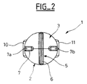
- the assistance tool 1 shown in the figures comprises a monobloc body 2, for example of a plastic material, which comprises a circular plate 3 which has a flat front face 4 on which is formed a projecting part 5 consisting of two diametrical ribs 6 and 7 which extend perpendicularly from so as to form a cross.
- the rib 6 extends from one edge to the other of the plate 3 while the rib 7 is formed by two parts 7a and 7b located on either side and at a distance from the rib 6, starting from the board edge 3.
- the tool 1 also comprises gripping means 8 which extend rearwards from the rear face 9 of the plate 3.
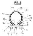
- These gripping means 8 comprise two branches 10 and 11 which are connected to the plate 3 by parallel portions 10a and 11a reduced thicknesses constituting joints, these portions being for example parallel to the rib 6 so that the passage between the branches 10 and 11 extends parallel to this rib.
- branches 10 and 11 are arched in an opposite manner in order to form an open ring between their free ends 10b and 11b.
- the dimension of the passage formed between branches 10 and 11 is thus variable dimension when branches 10 and 11 are pivoted around joints 10a and 11a.
- the legs of the branches 10 and 11 are connected by two legs 12 and 13, interconnected, dimensioned so that the branches 10 and 11 are likely to be kept elastically apart, as shown in particular in Figure 4, or close together, as the shows in particular Figure 5, on either side of a position intermediate.
- the gripping means 8 are thus adapted so that that tool 1 can be installed on a user's finger in the manner of a ring. He just has to pass his finger between the branches 10 and 11 and bring branches 10 and 11 together, placing the tray 3 on the outside of the finger.
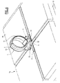
- the installer inserts between the plates 15, between their adjacent corners, a spacer or cross 17 in the shape of a star with four perpendicular branches, so that the spacing between the plates 15 is constant.
- the spacer 17 is placed flush with the front face of the plates 15.
- spacers 17 are inserted between the corners of all of the plates 15 constituting the wall 14.
- the installer Before the bonding material 16 is hardened, the installer presents the tool 1 in front of the spacer 17 in a position such that its ribs 6 and 7 extend respectively parallel to the branches of the spacer 17.
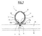
- the installer brings the ribs 6 and 7 of the tool 1 pressing on the spacer 17 and pressing so as to push it in by engaging the ribs 6 and 7 between the plates 15, until the front face 4 of the plate 3 comes in press against the outer face of the plates 15. After which, the installer remove tool 1.
- the installer does the same on all the spacers installed.
- the ribs 6 and 7 of the tool 1 are dimensioned so that their thickness, parallel to the front face 4 of the plate 3, is at most equal to the thickness of the branches of the spacer 17 so as to ability to freely engage between plates 15.
- the thickness of the ribs 6 and 7, perpendicular to the front face 4 of the plate 3, is such that when the front face 4 of the plate 3 is in abutment against the external face of the plates 15, the spacer 17 still extends between the plates 15, as shown in the Figure 8, so that their spacing is still maintained by this spacer 17.
- the distance from the front edge of the projecting part 5 and the front face 4 is at most equal to the thickness plates 15.
- the addition of the thickness of the ribs 6 and 7, perpendicular to the front face 4 of the plate 3, and the thickness of the spacer 17 is at most equal to the thickness of the plates 15, so that the spacer 17 remains between the plates 15 but is set back from their front faces.
- the tips of the ribs 6 and 7 come on the spacer 17 and the sides 18a and 18b of the ribs 6 and 7 constitute, before the front face 4 of the plate 3 reaches the face front of the plates 15, stops coming against the front corners of the plates 15 placed so as to limit the engagement of the ribs 6 and 7 between the plates 15.
- the penetration of the spacer 17 depends on the angle that form between them the sides 18a and 18b of the ribs 6 and 7 and of the distance between the plates 15 determined by the width of the branches of the spacer 17.
- the greater the penetration of the spacer that the distance between the plates 15 will be great, the limit being reached when the front face 4 of the plate 3 touches the front face of the plates 15.
Landscapes
- Engineering & Computer Science (AREA)
- Architecture (AREA)
- Civil Engineering (AREA)
- Structural Engineering (AREA)
- Mechanical Engineering (AREA)
- Finishing Walls (AREA)
- Road Paving Structures (AREA)
- Processing Of Stones Or Stones Resemblance Materials (AREA)
- Pit Excavations, Shoring, Fill Or Stabilisation Of Slopes (AREA)
Applications Claiming Priority (2)
| Application Number | Priority Date | Filing Date | Title |
|---|---|---|---|
| FR0112301A FR2830031B1 (fr) | 2001-09-25 | 2001-09-25 | Outil d'assistance a la pose de plaques de carrelage |
| FR0112301 | 2001-09-25 |
Publications (2)
| Publication Number | Publication Date |
|---|---|
| EP1296006A1 true EP1296006A1 (de) | 2003-03-26 |
| EP1296006B1 EP1296006B1 (de) | 2008-08-13 |
Family
ID=8867570
Family Applications (1)
| Application Number | Title | Priority Date | Filing Date |
|---|---|---|---|
| EP02292346A Expired - Lifetime EP1296006B1 (de) | 2001-09-25 | 2002-09-25 | Hilfswerkzeug zum Verlegen von Fliesenbelägen |
Country Status (4)
| Country | Link |
|---|---|
| EP (1) | EP1296006B1 (de) |
| AT (1) | ATE404758T1 (de) |
| DE (1) | DE60228179D1 (de) |
| FR (1) | FR2830031B1 (de) |
Cited By (1)
| Publication number | Priority date | Publication date | Assignee | Title |
|---|---|---|---|---|
| WO2010084341A1 (en) * | 2009-01-21 | 2010-07-29 | Gregg Robert Flanegan | Tile spacer punch device |
Families Citing this family (1)
| Publication number | Priority date | Publication date | Assignee | Title |
|---|---|---|---|---|
| FR2942490B1 (fr) * | 2009-02-20 | 2015-03-06 | Frederic Guilhabeau | Dispositif de nettoyage de l'espace destine a recevoir les joints de revetement tel le carrelage. |
Citations (3)
| Publication number | Priority date | Publication date | Assignee | Title |
|---|---|---|---|---|
| US2735321A (en) * | 1956-02-21 | Finger tip tools | ||
| DE2724128A1 (de) * | 1977-05-27 | 1978-12-07 | Ludwig Reiger | Mehrseitig selbstklebendes traeger- und fugenband |
| GB2331322A (en) * | 1997-11-15 | 1999-05-19 | Roger James Smith | Annular wall tile spacer |
Family Cites Families (3)
| Publication number | Priority date | Publication date | Assignee | Title |
|---|---|---|---|---|
| US4793068A (en) * | 1987-12-14 | 1988-12-27 | Homayun Golkar | Spacer for use in setting tile |
| US5288534A (en) * | 1992-12-28 | 1994-02-22 | Tavshanjian B Armen | Handy, multi-pupose tile installation spacers |
| US5732862A (en) * | 1997-02-14 | 1998-03-31 | Bull; Charles L. | Material holding apparatus with integrated finger mount |
-
2001
- 2001-09-25 FR FR0112301A patent/FR2830031B1/fr not_active Expired - Fee Related
-
2002
- 2002-09-25 AT AT02292346T patent/ATE404758T1/de not_active IP Right Cessation
- 2002-09-25 EP EP02292346A patent/EP1296006B1/de not_active Expired - Lifetime
- 2002-09-25 DE DE60228179T patent/DE60228179D1/de not_active Expired - Fee Related
Patent Citations (3)
| Publication number | Priority date | Publication date | Assignee | Title |
|---|---|---|---|---|
| US2735321A (en) * | 1956-02-21 | Finger tip tools | ||
| DE2724128A1 (de) * | 1977-05-27 | 1978-12-07 | Ludwig Reiger | Mehrseitig selbstklebendes traeger- und fugenband |
| GB2331322A (en) * | 1997-11-15 | 1999-05-19 | Roger James Smith | Annular wall tile spacer |
Cited By (2)
| Publication number | Priority date | Publication date | Assignee | Title |
|---|---|---|---|---|
| WO2010084341A1 (en) * | 2009-01-21 | 2010-07-29 | Gregg Robert Flanegan | Tile spacer punch device |
| US8763223B2 (en) | 2009-01-21 | 2014-07-01 | Gregg Robert Flanegan | Tile spacer punch device |
Also Published As
| Publication number | Publication date |
|---|---|
| FR2830031B1 (fr) | 2003-12-19 |
| ATE404758T1 (de) | 2008-08-15 |
| EP1296006B1 (de) | 2008-08-13 |
| FR2830031A1 (fr) | 2003-03-28 |
| DE60228179D1 (de) | 2008-09-25 |
Similar Documents
| Publication | Publication Date | Title |
|---|---|---|
| FR2630149A1 (fr) | Accessoire de pose pour panneau de revetement, en particulier panneau de sol | |
| EP1251285A1 (de) | Anordnung zur Zusammenstellung zweier Karrosserieteile, Kant gegen Kant , und Karrosserie , in dieser Weise zusammengesetzt | |
| WO2018024951A1 (fr) | Agrafe de maintien de deux elements plans | |
| FR2873771A1 (fr) | Attache femelle et obturateur la comportant | |
| EP0186217B1 (de) | Rahmen | |
| EP1296006A1 (de) | Hilfswerkzeug zum Verlegen von Fliesenbelägen | |
| EP0325642B1 (de) | Punktbefestigungsvorrichtung von elementen mit einem rand, insbesondere von platten auf einer tragkonstruktion | |
| FR2968141A1 (fr) | Appareillage electrique a support d'appareillage basculant | |
| FR2975717A1 (fr) | Insert dissociable de blocage vertical entre deux lames d'une structure plane de parement ou de parquet. | |
| EP0875975B1 (de) | Unterputzdose für elektrische Gerät in einer Wand geringer Dicke mit integrierter Spannlasche | |
| EP0418152B1 (de) | Modulares, insbesondere elektrisches, Gerät mit Schutzdeckel für Hinweisschilder | |
| FR2683570A1 (fr) | Sortie de toiture pour ventilation, en particulier pour ventilation mecanique controlee. | |
| FR2609615A1 (fr) | Dispositif d'encadrement pour photographies, gravures ou autres | |
| FR2681402A1 (fr) | Profiles d'ossature, notamment pour armoire pour appareillages electriques, et accessoires susceptibles d'etre associes a un tel profile d'ossature. | |
| EP2570566A2 (de) | Fugenabdeckungsvorrichtung für Bodenbelag | |
| WO2019243737A1 (fr) | Procédé de réalisation d'un parement | |
| FR2616822A1 (fr) | Dispositif de fixation d'un panneau sur des montants | |
| FR2867174A1 (fr) | Cabine pour ascenseur | |
| CH357539A (fr) | Ensemble d'ééments destinés à être juxtaposés | |
| FR2820380A1 (fr) | Vehicule automobile avec au moins une barre de toit | |
| FR2589706A1 (fr) | Garniture pour plateau-repas | |
| EP0859096A1 (de) | Fassadenkonstruktion, Pfosten für eine derartige Fassadenkonstruktion und Montagemethode für Riegel in dem Fassadenkonstruktion | |
| BE668586A (de) | ||
| FR2762183A1 (fr) | Ossature d'armoire, et armoire correspondante, notamment pour appareillages electriques | |
| FR2702680A3 (fr) | Dispositif pour peindre des arêtes ou coins extérieurs ou intérieurs. |
Legal Events
| Date | Code | Title | Description |
|---|---|---|---|
| PUAI | Public reference made under article 153(3) epc to a published international application that has entered the european phase |
Free format text: ORIGINAL CODE: 0009012 |
|
| AK | Designated contracting states |
Kind code of ref document: A1 Designated state(s): AT BE BG CH CY CZ DE DK EE ES FI FR GB GR IE IT LI LU MC NL PT SE SK TR |
|
| AX | Request for extension of the european patent |
Extension state: AL LT LV MK RO SI |
|
| 17P | Request for examination filed |
Effective date: 20030922 |
|
| AKX | Designation fees paid |
Designated state(s): AT BE BG CH CY CZ DE DK EE ES FI FR GB GR IE IT LI LU MC NL PT SE SK TR |
|
| 17Q | First examination report despatched |
Effective date: 20070808 |
|
| GRAP | Despatch of communication of intention to grant a patent |
Free format text: ORIGINAL CODE: EPIDOSNIGR1 |
|
| GRAS | Grant fee paid |
Free format text: ORIGINAL CODE: EPIDOSNIGR3 |
|
| GRAA | (expected) grant |
Free format text: ORIGINAL CODE: 0009210 |
|
| AK | Designated contracting states |
Kind code of ref document: B1 Designated state(s): AT BE BG CH CY CZ DE DK EE ES FI FR GB GR IE IT LI LU MC NL PT SE SK TR |
|
| REG | Reference to a national code |
Ref country code: GB Ref legal event code: FG4D Free format text: NOT ENGLISH |
|
| REG | Reference to a national code |
Ref country code: CH Ref legal event code: EP |
|
| REG | Reference to a national code |
Ref country code: IE Ref legal event code: FG4D Free format text: LANGUAGE OF EP DOCUMENT: FRENCH |
|
| REF | Corresponds to: |
Ref document number: 60228179 Country of ref document: DE Date of ref document: 20080925 Kind code of ref document: P |
|
| PG25 | Lapsed in a contracting state [announced via postgrant information from national office to epo] |
Ref country code: NL Free format text: LAPSE BECAUSE OF FAILURE TO SUBMIT A TRANSLATION OF THE DESCRIPTION OR TO PAY THE FEE WITHIN THE PRESCRIBED TIME-LIMIT Effective date: 20080813 Ref country code: ES Free format text: LAPSE BECAUSE OF FAILURE TO SUBMIT A TRANSLATION OF THE DESCRIPTION OR TO PAY THE FEE WITHIN THE PRESCRIBED TIME-LIMIT Effective date: 20081124 |
|
| PG25 | Lapsed in a contracting state [announced via postgrant information from national office to epo] |
Ref country code: FI Free format text: LAPSE BECAUSE OF FAILURE TO SUBMIT A TRANSLATION OF THE DESCRIPTION OR TO PAY THE FEE WITHIN THE PRESCRIBED TIME-LIMIT Effective date: 20080813 Ref country code: AT Free format text: LAPSE BECAUSE OF FAILURE TO SUBMIT A TRANSLATION OF THE DESCRIPTION OR TO PAY THE FEE WITHIN THE PRESCRIBED TIME-LIMIT Effective date: 20080813 |
|
| BERE | Be: lapsed |
Owner name: CHAPELON, GILBERT PAUL Effective date: 20080930 |
|
| REG | Reference to a national code |
Ref country code: IE Ref legal event code: FD4D |
|
| PG25 | Lapsed in a contracting state [announced via postgrant information from national office to epo] |
Ref country code: DK Free format text: LAPSE BECAUSE OF FAILURE TO SUBMIT A TRANSLATION OF THE DESCRIPTION OR TO PAY THE FEE WITHIN THE PRESCRIBED TIME-LIMIT Effective date: 20080813 Ref country code: IE Free format text: LAPSE BECAUSE OF FAILURE TO SUBMIT A TRANSLATION OF THE DESCRIPTION OR TO PAY THE FEE WITHIN THE PRESCRIBED TIME-LIMIT Effective date: 20080813 Ref country code: BG Free format text: LAPSE BECAUSE OF FAILURE TO SUBMIT A TRANSLATION OF THE DESCRIPTION OR TO PAY THE FEE WITHIN THE PRESCRIBED TIME-LIMIT Effective date: 20081113 Ref country code: MC Free format text: LAPSE BECAUSE OF NON-PAYMENT OF DUE FEES Effective date: 20080930 |
|
| PGFP | Annual fee paid to national office [announced via postgrant information from national office to epo] |
Ref country code: FR Payment date: 20080926 Year of fee payment: 7 |
|
| REG | Reference to a national code |
Ref country code: CH Ref legal event code: PL |
|
| PG25 | Lapsed in a contracting state [announced via postgrant information from national office to epo] |
Ref country code: PT Free format text: LAPSE BECAUSE OF FAILURE TO SUBMIT A TRANSLATION OF THE DESCRIPTION OR TO PAY THE FEE WITHIN THE PRESCRIBED TIME-LIMIT Effective date: 20090113 Ref country code: SK Free format text: LAPSE BECAUSE OF FAILURE TO SUBMIT A TRANSLATION OF THE DESCRIPTION OR TO PAY THE FEE WITHIN THE PRESCRIBED TIME-LIMIT Effective date: 20080813 Ref country code: CZ Free format text: LAPSE BECAUSE OF FAILURE TO SUBMIT A TRANSLATION OF THE DESCRIPTION OR TO PAY THE FEE WITHIN THE PRESCRIBED TIME-LIMIT Effective date: 20080813 |
|
| PLBE | No opposition filed within time limit |
Free format text: ORIGINAL CODE: 0009261 |
|
| STAA | Information on the status of an ep patent application or granted ep patent |
Free format text: STATUS: NO OPPOSITION FILED WITHIN TIME LIMIT |
|
| 26N | No opposition filed |
Effective date: 20090514 |
|
| GBPC | Gb: european patent ceased through non-payment of renewal fee |
Effective date: 20081113 |
|
| PG25 | Lapsed in a contracting state [announced via postgrant information from national office to epo] |
Ref country code: EE Free format text: LAPSE BECAUSE OF FAILURE TO SUBMIT A TRANSLATION OF THE DESCRIPTION OR TO PAY THE FEE WITHIN THE PRESCRIBED TIME-LIMIT Effective date: 20080813 Ref country code: BE Free format text: LAPSE BECAUSE OF NON-PAYMENT OF DUE FEES Effective date: 20080930 |
|
| PG25 | Lapsed in a contracting state [announced via postgrant information from national office to epo] |
Ref country code: DE Free format text: LAPSE BECAUSE OF NON-PAYMENT OF DUE FEES Effective date: 20090401 Ref country code: IT Free format text: LAPSE BECAUSE OF FAILURE TO SUBMIT A TRANSLATION OF THE DESCRIPTION OR TO PAY THE FEE WITHIN THE PRESCRIBED TIME-LIMIT Effective date: 20080813 |
|
| PG25 | Lapsed in a contracting state [announced via postgrant information from national office to epo] |
Ref country code: LI Free format text: LAPSE BECAUSE OF NON-PAYMENT OF DUE FEES Effective date: 20080930 Ref country code: CH Free format text: LAPSE BECAUSE OF NON-PAYMENT OF DUE FEES Effective date: 20080930 |
|
| PG25 | Lapsed in a contracting state [announced via postgrant information from national office to epo] |
Ref country code: GB Free format text: LAPSE BECAUSE OF NON-PAYMENT OF DUE FEES Effective date: 20081113 |
|
| PG25 | Lapsed in a contracting state [announced via postgrant information from national office to epo] |
Ref country code: SE Free format text: LAPSE BECAUSE OF FAILURE TO SUBMIT A TRANSLATION OF THE DESCRIPTION OR TO PAY THE FEE WITHIN THE PRESCRIBED TIME-LIMIT Effective date: 20081113 |
|
| REG | Reference to a national code |
Ref country code: FR Ref legal event code: ST Effective date: 20100531 |
|
| PG25 | Lapsed in a contracting state [announced via postgrant information from national office to epo] |
Ref country code: LU Free format text: LAPSE BECAUSE OF NON-PAYMENT OF DUE FEES Effective date: 20080925 Ref country code: FR Free format text: LAPSE BECAUSE OF NON-PAYMENT OF DUE FEES Effective date: 20090930 Ref country code: CY Free format text: LAPSE BECAUSE OF FAILURE TO SUBMIT A TRANSLATION OF THE DESCRIPTION OR TO PAY THE FEE WITHIN THE PRESCRIBED TIME-LIMIT Effective date: 20080813 |
|
| PG25 | Lapsed in a contracting state [announced via postgrant information from national office to epo] |
Ref country code: TR Free format text: LAPSE BECAUSE OF FAILURE TO SUBMIT A TRANSLATION OF THE DESCRIPTION OR TO PAY THE FEE WITHIN THE PRESCRIBED TIME-LIMIT Effective date: 20080813 |
|
| PG25 | Lapsed in a contracting state [announced via postgrant information from national office to epo] |
Ref country code: GR Free format text: LAPSE BECAUSE OF FAILURE TO SUBMIT A TRANSLATION OF THE DESCRIPTION OR TO PAY THE FEE WITHIN THE PRESCRIBED TIME-LIMIT Effective date: 20081114 |