EP1296038A2 - Verschliessen von Bohrungen mit in diese einsetzbaren Verschlussdeckeln - Google Patents
Verschliessen von Bohrungen mit in diese einsetzbaren Verschlussdeckeln Download PDFInfo
- Publication number
- EP1296038A2 EP1296038A2 EP02020324A EP02020324A EP1296038A2 EP 1296038 A2 EP1296038 A2 EP 1296038A2 EP 02020324 A EP02020324 A EP 02020324A EP 02020324 A EP02020324 A EP 02020324A EP 1296038 A2 EP1296038 A2 EP 1296038A2
- Authority
- EP
- European Patent Office
- Prior art keywords
- bore
- side wall
- cover
- wall
- base
- Prior art date
- Legal status (The legal status is an assumption and is not a legal conclusion. Google has not performed a legal analysis and makes no representation as to the accuracy of the status listed.)
- Withdrawn
Links
Images


Classifications
-
- F—MECHANICAL ENGINEERING; LIGHTING; HEATING; WEAPONS; BLASTING
- F02—COMBUSTION ENGINES; HOT-GAS OR COMBUSTION-PRODUCT ENGINE PLANTS
- F02B—INTERNAL-COMBUSTION PISTON ENGINES; COMBUSTION ENGINES IN GENERAL
- F02B77/00—Component parts, details or accessories, not otherwise provided for
- F02B77/005—Plugs
Definitions
- the invention relates to a closure cap for insertion in and closing bores, especially of Mounting holes in gear or motor housings, with one domed lid base and one across, along it The circumferential side wall, the facing each other Sides of the lid base and side wall an interior limit and when inserted in a hole the Lid bottom spanned the opening of the hole and the Side wall by deforming the sealing cap with pressure the inner wall of the bore.
- the invention relates also on a sealing connection between one Bore and such a cover and a method and a tool for inserting such a cover in a hole.
- Such a cover as z. B. for closing Mounting holes in gear and motor housings and also in other housings are used to ensure a secure seal ensure and also an internal pressure withstand external loads.
- Caps of the type mentioned are from the DIN 443 known. They face the hole in which they are should be used in excess and are used in the Hole pressed in by insertion. Through the press fit a tight fit is initially achieved. However, they can known closure cover for vibrations from the bore wander out or fall out.
- a disadvantage of the known Sealing caps also ensure that it is pressed in Damage can occur.
- the caps are off one coated on one or both sides with elastomer Made of sheet steel; pressing in can replace the Elastomer coating and thus lead to leaks.
- the sealing surface in the bore can possibly be existing punch burr on the steel sheet can be damaged. moreover it is difficult with the conventional caps to form low lid heights, since known closure lids can easily tip over at a low height during assembly.
- the object of the present invention is in it with the least possible assembly effort and larger Variety of dimensions a safe and permanent sealing of the Allow closure cap in the bore.
- this object is achieved with a closure cover of the type mentioned solved in that in the undeformed Condition of the lid of the lid in the Interior is arched and the outer dimensions of the Sidewall at most equal to the inside dimensions of the hole are, and that the lid bottom and the side wall to the outside are so plastically deformable that the curvature of the Lid bottom can be reduced and at the same time the scope of the Cover bottom and at least the adjoining area the side wall can be expanded to the extent that it is inserted Condition of the cover the side wall with pressure on the Inner wall of the hole can be created.
- a method of insertion is also used to achieve the object a closure cover according to the invention with the steps according to claim 10 and a tool for performing the Method proposed with the features of claim 15.
- a hole can be drilled through the measures according to the invention can be closed tightly and tightly in a relatively simple manner.
- an inventive Sealing lid without any effort into which holes are inserted; because of its plastic It can then be deformed.
- an inventive Closure cover can this in the area of its side wall Pressure to be pressed against the inner wall of the bore, whereby the towards the free side edge of the side wall, d. H. in the Interior of the cover lid arched lid base in a less domed, flatter state of deformation becomes. In this way the contact pressure of the side wall increased to the inner wall of the bore and due to the permanent plastic deformation state also permanent maintained.
- the can in a bore used closure cap according to the invention very convenient be plastically deformed. Only the feet of the Spreading elements and the end face of the stamp in the interior of the cap are inserted, with the feet protrude beyond the face and then along the stamp the insides of the feet are moved around this to push outwards transversely to the direction of movement of the stamp.
- the feet are pressed so far that the outer sides of the side wall of the closure lid in their press the desired plastic shape against the inner wall of the hole, at the same time the end face of the stamp on the Lid bottom presses to reduce its curvature or curvature. This causes the lid to widen on its circumference and increases the pressure of the side wall on the inner wall the hole. Due to the plastic deformation that occurs of the lid base and at least the one connected to it Area of the side wall remains the applied one Maintain pressure even after removing the tool.
- the lid base is essentially one flat state can be pressed. This will put the on the side wall exercisable force and thus the pressing force with which the Side wall permanently pressed onto the inner wall of the hole is maximized.
- the outer dimensions of the Sidewall at most equal to the inner dimensions of a sealing bead, which is in the circumferential direction on the inner wall of the Bore extends, and are the lid bottom and side wall as far as plastically deformable, that in the deformed state the lid of the lid and the adjoining Area of the side wall up to the inner wall can reach under the hole.
- a closure cover according to the invention is preferred from one side sheet metal coated with elastomer, e.g. B. from stainless Material such as aluminum or stainless steel, formed, the elastomer coated side being the outside of the closure lid forms. As a result, the tightness is again between cover and hole increased.
- elastomer e.g. B. from stainless Material such as aluminum or stainless steel
- the cover can also be made from both sides Elastomer coated sheet can be formed.
- the inner elastomer coating then serves as corrosion protection for the Use of rust-prone material, e.g. B. of sheet steel.
- a sealing connection Preferably runs with a sealing connection according to the invention on the inner wall of the hole in the circumferential direction a sealing bead, the on the inner wall of the bore adjacent area of the side wall of the closure cover Seals undercut or undercut.
- the sealing bead runs particularly preferably at the edge of the Inner wall of the bore.
- the lid base is advantageously in an essentially flat plastic Deformation state pressed to apply as much pressure as possible the side wall of the cover to the inner wall to achieve the hole.
- the inner wall the hole at a predetermined distance from their Edge of a retaining bead under the lid base or projection are shaped, the distance being given in this way that the cap when it is so far in the hole is inserted until the lid bottom on the retaining projection rests, has reached its target position.
- the Cap to reach its target position so far in the Drilled hole until the collar on the surrounding the hole Workpiece or housing surface is applied. In this way the closure cover can be precisely in with simple means to be brought to his debit position.
- the inner surface of the ring lies on the peripheral surface of the tool of the stamp.
- the end face of the stamp is preferably flat. On the one hand can with such a trained stamp the lid base pressed in a substantially flat state and on the other hand, such a stamp is very easy produced.
- the feet widen to their free End. In this way, an inclined towards the stamp Inside and one towards the side wall of the cover inclined outside of the feet are formed.
- the The bottom of the feet facing away from the ring faces the outside inclined towards and away from the ring.
- an outer edge is formed, which can be engaged in the transition area between the lid base and the side wall, d. H. into the lid bottom and side wall Inner edge, a closure lid is formed.
- the So feet have a secure hold on the inner wall of the Sidewall and can the deformation force both on the Circumferential area of the lid base as well as on it Apply the subsequent area of the side wall securely.
- the outer edge of the feet is very particularly preferred and the end face of the stamp can be brought into one plane. With these measures is a transfer of the lid base from his undeformed, arched initial state in the essentially flat, plastically deformed state in a simple way possible.
- this Tool four spreading elements, each of which is almost Extend 90 ° in the circumferential direction along the ring. hereby becomes a very low manufacturing cost Accurate expansion of the closure lid achieved.
- FIG. 1 of an inventive Cap 1 is rotationally symmetrical a longitudinal axis 2 formed around and has a lid bottom 3, one on the edge 4 extending in the circumferential direction Side wall 5 and a collar running in the circumferential direction 6 on.
- the lid base 3 is over over its entire surface inside, d. H. in the interior 7 between the lid base 3 and Side wall 5 in or to the free edge 8 of the side wall 5 monotonously curved or curved, the apex 9 lies on the longitudinal axis 2.
- the side wall 5 is cylindrical and includes its one edge 10 on the peripheral edge 4 of the lid base 3 on. There is between the lid base 3 and the side wall 5 a transition radius is formed so that this transition region 11 both on the inside 12 and on the outside 13 is rounded.
- a radially outwardly projecting collar 6 is formed on the free edge 8 of the side wall facing away from the lid base 3 5 .
- the cover 1 is made of an elastomer-coated Sheet metal, for example, made by deep drawing.
- Sheets come in all suitable plastically deformable materials considered, e.g. B. conventional steel sheets, sheets of stainless steel or aluminum.
- Will a sheet of metal a rustproof material one is sufficient Elastomer coating on the side of the sheet that the Outside 13 of the closure cover 1, that is to say that of the bore 14 facing side of the cap should form.
- a rust-sensitive sheet for the production of the Closure cover 1 used is an elastomer coated on both sides Output sheet inserted. The coating is used here on the later inside 12 of the cover 1 as corrosion protection.
- FIG. 2 shows the closure cover 1 shown in FIG. 1 in a bore 14 of a housing or workpiece 15a shown installed condition.
- the bore 14 runs after outside to the housing outer surface or workpiece surface 15 with a sealing bead 16.
- the bore 14 thus points to her Margin 17, d. H. at their exiting into the workpiece surface 15 End, a sealing bead 16, which extends from the inner wall 18 of the bore 14 extends radially inwards.
- the Outside diameter of the side wall 5 of the closure cover 1 is in its undeformed state slightly smaller than the inside diameter of the sealing bead 16 so that the sealing cover 1 easily and without pressure with a clearance fit in the sealing surface the hole 14 can be inserted.
- the cap 1 is in its deformed state in the transition area 11 between Lid base 3 and side wall 5 radially expanded and the Lid bottom 3 almost flat.
- the transition region 11, i. H. the Circumferential edge 4 of the lid base 3 and the adjoining one Area of the side wall 5 are on the inner wall 18 of the Bore 14 and thus engage under the sealing bead 16.
- FIGS. 3 and 4 The inventive method and a first embodiment of a tool 20 according to the invention for plastic Deformation of the closure cover 1 is shown in FIGS. 3 and 4 removable.
- a closure cover 1 is produced or provided, whose side wall 5 has an outer diameter that is slightly smaller than the inside diameter of the bore 14.
- the side wall 5 has outer diameter that is slightly less than that Inner diameter of the sealing bead 16.
- the Cap 1 powerless, d. H. with match in which Hole 14 can be inserted.
- the cap 1 is inserted so far into the bore 14, until the collar 6 of the cap 1 on the Bore 14 surrounding workpiece surface 15 rests.
- the Cover 1 has then reached its target or end position.
- on the inside 12 of the lid base 3 pressed up to its curvature reduce to an almost flat state of deformation, and at the same time, the lid circumference 4 and the side wall 5 pressed radially outward to expand it so far that they rest on the inner wall 18 of the bore 14 with pressure.
- the lid base pressed into an almost flat state of deformation 3 acts like a strut that supports the pressure applies to the lid edge 4 and the side wall 5 and this also permanently maintained when the deformation tool 20 is removed again.
- the deformation tool 20 has an elongated punch 21 and a sleeve-shaped expansion part surrounding the stamp 21 22 on.
- the stamp is 21st cylindrical with a flat end face 23, the provided for contact with the inside 12 of the lid base 3 is.
- the stamp 21 is in the longitudinal direction thereof Spreading part 22 slidable.
- the expansion part 22 has a ring 24 which the stamp 21st encloses and with its inner surface 25 on the cylindrical Circumferential surface 26 of the stamp 21 abuts.
- the Deformation sections 30 initially run from the ring 24 cylindrical and from about half of its length inwards towards the peripheral surface 26 of the stamp 21. she are radially elastically deformable or bendable, so that the Foot portions 31 by bending the deformation portions 30 are radially movable outwards.
- the foot sections 31 have an outside 32 for contact the inside 12 of the side wall 5 of the closure cover 1, an inner side 33 for contact with the peripheral surface 26 of the Stamp 21 and an underside 34 for contact with the Inside 12 of the lid base 3.
- the Outer diameter of the foot portions 31 slightly less than that Inner diameter of the side wall 5, so that the foot sections 31 easily inserted into the undeformed cover 1 can be.
- the outside 32 and the inside 33 of the foot portions 31 extend from the deformation section 30 to the outside or inclined inwards so that the foot sections 31 to widen their bottom 34 out.
- the radial distance between the Inner sides 33 of the foot sections 31 are smaller than the diameter the peripheral surface 26 of the stamp 21, so that the Inner sides 33 of the foot sections 31 are at least partially radial protrude inward beyond the end face 23 of the stamp 21.
- This supernatant is dimensioned such that the spread of the Spreading elements 28 reaches their target value when the insides 33 of the feet 31 in the area of their smallest diameter rest on the peripheral surface of the displaced stamp, d. H. if the end face 23 of the stamp 21 on the inside 33 of the feet 31 survives.
- the from the peripheral surface 26th and the end face 23 of the stamp 21 is formed edge 35 in the example shown rounded and gliding when moving on the inner sides 33 of the foot sections 31.
- the outer sides 32 of the foot portions 31 are shaped and dimensioned so that they are in fully spread shape the inner wall of the side wall 5 of the cover 1 in form their plastically deformed target state (FIG. 4).
- the undersides 34 of the feet 31 run from the inside thereof 33 obliquely outwards to the side facing away from the ring 24, so that they are on the inside 12 of the domed lid base 3 can create.
- the functioning of the tool 20 is as follows:
- the stamp 21 is opposite the spreading elements 28 withdrawn so that the foot portions 31 over the end face 23 of the stamp 21 protrude and the Deformation sections 30 are in the undeformed state (FIG 3).
- the tool 20 is in the Interior 7 of the one already in the bore 14 Cap 1 inserted until the undersides 34th the foot sections 31 on the inside 12 of the lid base 3 rest.
- the stamp 21 is in the direction of the foot sections 31, d. H. 3 and 4 moved downwards, the edge 35 between the peripheral surface 26 and the end surface 23 of the stamp 21 along the inner sides 33 of the foot sections 31 slides and thereby this radially outwards suppressed.
- the end face 23 comes to rest on the Inside 12 of the domed lid base 3 and presses it outwards, d. H. in Figures 3 and 4 down so that its curvature decreases.
- the stamp 21 is moved down as far as until the end face 23 and the outer edges of the Leg sections 31 are located in one plane, which makes the lid bottom 3 in a substantially flat plastic deformation state has been brought and the cover 1 overall reached its plastic target deformation state.
- the one enclosing the stamp 21 has and on this adjacent ring 24 on his Spreading elements 28 end facing a radially outward projecting collar 36.
- the collar 36 are two each other diametrically opposite through holes 37 are formed, those for holding fasteners to fix the position serve the expansion part 22.
- the spreading elements 28 have, as in the embodiment 3 and 4, a deformation section 30 and a foot section 31.
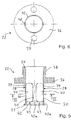
- the sleeve-shaped Spreading part 22 in its wall 39 between the collar 36 and the foot sections 31 four in the longitudinal direction of the sleeve Openings or openings 40, which differ from the underside of the federal government 36 facing the foot sections 31 from a predetermined distance from the second end, d. H. extend to the beginning of the foot sections 31.
- the between the openings 40 permanent material web 41 forms in each case the deformation section 30 of an expansion element 28 out.
- In the between the openings 40 and the second End remaining circumferential wall section or material web 42 runs between each Opening 40 and the second end in the longitudinal direction Slot 43 to form four leg portions 31.
- the spreading elements 28 are thus each one in the longitudinal direction of the sleeve extending web 41 between two openings 40 and one extending in the circumferential direction the openings 40 connecting material web section 42a formed.
- the foot sections 31 are like those in FIGS. 3 and 4 shown foot portions 31 with outer sides 32 which in fully spread condition essentially the shape of the Inner wall of the side wall 5 of the closure cover 1 in its plastically deformed target state, also with Inner sides 33, which are in the non-spread state of the expansion elements 28 radially inward over the peripheral surface 23 of the Stamp 21 protrude, and provided with undersides 34, the not to abut the arched lid base 3 deformed state are provided.
- this expansion part 22 corresponds to that of Spreading part 22 shown in FIGS. 3 and 4.
Landscapes
- Engineering & Computer Science (AREA)
- Chemical & Material Sciences (AREA)
- Combustion & Propulsion (AREA)
- Mechanical Engineering (AREA)
- General Engineering & Computer Science (AREA)
- Closures For Containers (AREA)
- Pressure Vessels And Lids Thereof (AREA)
Abstract
Description
- Figur 1
- in einer Querschnittsansicht eine Ausführungsform eines erfindungsgemäßen Verschlußdeckels im unverformten Zustand;
- Figur 2
- in einer Querschnittsansicht eine Dichtverbindung zwischen einer Bohrung und dem Verschlußdeckel aus Figur 1 in dessen verformten Zustand;
- Figur 3
- in einer Querschnittsansicht den unverformten Verschlußdeckel aus Figur 1 und eine teilweise geschnittene Ansicht einer ersten Ausführungsform eines erfindungsgemäßen Werkzeuges, im in den Verschlußdeckel eingeführten, noch nicht gespreizten Zustand;
- Figur 4
- in einer Querschnittsansicht den verformten Verschlußdeckel aus Figur 2 und eine der Figur 3 ähnliche Ansicht der ersten Ausführungsform eines erfindungsgemäßen Werkzeuges, im in den Verschlußdeckel eingeführten und gespreizten Zustand;
- Figur 5
- eine Querschnittsansicht durch eine zweite Ausführungsform eines erfindungsgemäßen Spreizteils;
- Figur 6
- eine Querschnittsansicht längs Linie VI-VI in Figur 5.
Claims (24)
- Verschlußdeckel zum Einsetzen in und Verschließen von Bohrungen, insbesondere von Montagebohrungen in Getriebeoder Motorgehäusen, mit einem gewölbten Deckelboden und einer quer zu diesem, längs dessen Umfang verlaufenden Seitenwand, wobei die einander zugewandten Seiten von Deckelboden und Seitenwand einen Innenraum begrenzen und im in eine Bohrung eingesetzten Zustand der Deckelboden die Öffnung der Bohrung überspannt und die Seitenwand durch Verformung des Verschlußdeckels mit Druck an der Innenwandung der Bohrung anliegt,
dadurch gekennzeichnet, daß im unverformten Zustand des Verschlußdeckels (1) der Deckelboden (3) in den Innenraum (7) hineingewölbt ist und die Außenabmessungen der Seitenwand (5) höchstens gleich den Innenabmessungen der Bohrung (14) sind, und
daß der Deckelboden (3) und die Seitenwand (5) nach außen hin derart plastisch verformbar sind, daß die Wölbung des Deckelbodens (3) verringerbar ist und gleichzeitig der Umfang (4) des Deckelbodens (3) und zumindest der daran anschließende Bereich der Seitenwand (5) soweit aufweitbar sind, daß im eingesetzten Zustand des Verschlußdeckels (1) die Seitenwand (5) mit Druck an die Innenwandung (18) der Bohrung (14) anlegbar ist. - Verschlußdeckel nach Anspruch 1, dadurch gekennzeichnet, daß der Deckelboden (3) in einen im wesentlichen ebenen Zustand drückbar ist.
- Verschlußdeckel nach Anspruch 1 oder 2, dadurch gekennzeichnet, daß im unverformten Zustand des Verschlußdeckels (1) die Außenabmessungen der Seitenwand (5) höchstens gleich den Innenabmessungen eines Dichtwulstes (16) sind, der sich in Umfangsrichtung auf der Innenwandung (18) der Bohrung (14) erstreckt, und daß der Deckelboden (3) und die Seitenwand (5) soweit plastisch verformbar sind, daß im verformten Zustand des Verschlußdeckels (1) der Deckelboden (3) und der daran anschließende Bereich der Seitenwand (5) den Dichtwulst (16) bis zur Innenwandung (18) der Bohrung (14) untergreifen können.
- Verschlußdeckel nach einem der Ansprüche 1 bis 3, dadurch gekennzeichnet, daß er aus einseitig mit Elastomer beschichtetem Blech gebildet ist, wobei die elastomerbeschichtete Seite die Außenseite (13) bildet.
- Verschlußdeckel nach einem der Ansprüche 1 bis 3, dadurch gekennzeichnet, daß er aus beidseitig mit Elastomer beschichtetem Blech gebildet ist.
- Verschlußdeckel nach einem der Ansprüche 1 bis 5, dadurch gekennzeichnet, daß sich von dem dem Deckelboden (3) abgewandten freien Rand (8) der Seitenwand (5) aus quer nach außen ein Bund (6) erstreckt, der an die an die Bohrung (14) angrenzenden Werkstückoberfläche (15) anlegbar ist.
- Dichtverbindung zwischen einer Bohrung (14), insbesondere einer Montagebohrung in Getriebe- oder Motorgehäusen, und einem Verschlußdeckel (1) nach einem der Ansprüche 1 bis 6.
- Dichtverbindung nach Anspruch 7 in Verbindung mit einem Verschlußdeckel nach Anspruch 3, dadurch gekennzeichnet, daß die Innenwandung (18) der Bohrung (14) in Umfangsrichtung einen Dichtwulst (16) ausbildet, wobei der an der Innenwandung (18) der Bohrung (14) anliegende Bereich der Seitenwand (5) des Verschlußdeckels (1) den Dichtwulst (16) untergreift.
- Dichtverbindung nach Anspruch 8, dadurch gekennzeichnet, daß der Dichtwulst (16) am Rand (17) der Innenwandung (18) der Bohrung (14) verläuft.
- Verfahren zum Einsetzen eines Verschlußdeckels nach einem der Ansprüche 1 bis 6 in eine Bohrung, mit den folgenden Schritten:a) Bereitstellen eines Verschlußdeckels (1), dessen Außenabmessungen mit den Innenabmessungen der Bohrung (14) eine vorgegebene Spielpassung ausbilden;b) Einführen des Verschlußdeckels (1) mit in Einführungsrichtung vorne liegendem Deckelboden (3) in die Bohrung (14) soweit, bis der Verschlußdeckel (1) in Längsrichtung der Bohrung (14) in seiner Sollage liegt;c) Plastisches Aufweiten des Deckelbodens (3) und der Seitenwand (5), bis die Seitenwand (5) mit Druck an der Innenwandung (18) der Bohrung (14) anliegt;d) und gleichzeitig Drücken des Deckelbodens (3) in einen plastischen Verformungszustand mit verringerter Wölbung.
- Verfahren nach Anspruch 10, dadurch gekennzeichnet, daß der Deckelboden (3) in einen im wesentlichen ebenen plastischen Verformungszustand gedrückt wird.
- Verfahren nach Anspruch 10 oder 11, dadurch gekennzeichnet, daß ein Verschlußdeckel (1) bereitgestellt wird, dessen Außenabmessungen eine Spielpassung mit den Innenabmessungen eines Dichtwulstes (16) ausbilden, der sich in Umfangsrichtung auf der Innenwandung (18) der Bohrung (14) erstreckt.
- Verfahren nach einem der Ansprüche 10 bis 12 in Verbindung mit einem der Ansprüche 1 bis 5, dadurch gekennzeichnet, daß auf der Innenwandung (18) der Bohrung (14) in einem vorgegebenen Abstand von deren Rand ein den Deckelboden (3) untergreifender Haltevorsprung geformt wird, wobei der Abstand so vorgegeben wird, daß der Verschlußdeckel (1) bei Auflage des Deckelbodens (3) auf dem Haltevorsprung seine Sollage erreicht hat.
- Verfahren nach einem der Ansprüche 10 bis 12 in Verbindung mit Anspruch 6, dadurch gekennzeichnet, daß der Verschlußdeckel (1) zum Erreichen seiner Sollage soweit in die Bohrung (14) eingeführt wird, bis der Bund (6) an der die Bohrung (14) umgebenden Werkstückoberfläche (15) anliegt.
- Werkzeug zur Durchführung des Verfahrens nach einem der Ansprüche 10 bis 14, mit
einem länglichen Stempel (21), der eine Stirnfläche (23) zur Anlage an den Deckelboden (3) und eine Umfangsfläche (26) aufweist, und
einem hülsenförmigen Spreizteil (22), das den Stempel (21) umgibt, wobei der Stempel (21) gegenüber dem Spreizteil (22) in Längsrichtung verschiebbar ist, und aufweisteinen Ring (24), der den Stempel (21) umschließt, undeine Mehrzahl von länglichen Spreizelementen (28), die in Umfangsrichtung des Rings (24) gleichmäßig verteilt angeordnet und jeweils mit ihrem ersten Ende an diesem befestigt sind, sich längs des Stempels (21) erstrecken und in dem an ihr zweites Ende angrenzenden Bereich jeweils einen Fuß (31) ausbilden mit einer dem Stempel (21) zugewandten Innenseite (33) und einer zur Anlage an die Innenwandung der Seitenwand (5) vorgesehenen Außenseite (32), wobei die Längsränder benachbarter Spreizelemente (28) zumindest im Fußbereich (31) nahe beieinander liegen, undwobei die Spreizelemente (28) elastisch nach außen hin verformbar sind und im unverformten Zustand die Füße (31) in Längsrichtung sowie nach innen über die Stirnfläche (23) überstehen und im verformten Zustand der Stempel (21) zum zweiten Ende hin verschoben ist, die Innenseiten (33) der Füße (31) an der Umfangsfläche (26) des Stempels (21) mit Druck anliegen und die Außenseiten (32) der Füße (31) im wesentlichen die Sollform der Innenwandung der Seitenwand (5) in deren plastisch verformten Zustand ausbilden. - Werkzeug nach Anspruch 15, dadurch gekennzeichnet, daß die Innenfläche (25) des Rings (24) an der Umfangsfläche (26) des Stempels (21) anliegt.
- Werkzeug nach Anspruch 15 oder 16, dadurch gekennzeichnet, daß die Stirnfläche (23) des Stempels (21) eben ist.
- Werkzeug nach einem der Ansprüche 15 bis 17, dadurch gekennzeichnet, daß zwischen der Stirnfläche (23) und der Umfangsfläche (26) des Stempels (21) eine Kante (35) ausgebildet ist, die zum Überführen der Spreizelemente (28) vom unverformten in den verformten Zustand und umgekehrt auf den Innenseiten (33) der Füße (31) gleitet.
- Werkzeug nach einem der Ansprüche 15 bis 18, dadurch gekennzeichnet, daß die Füße (31) sich zu ihrem freien Ende hin verbreitern.
- Werkzeug nach einem der Ansprüche 15 bis 19, dadurch gekennzeichnet, daß die dem Ring (24) abgewandte Unterseite (34) der Füße (31) jeweils zur Außenseite (32) und zur vom Ring (24) abgewandten Seite hin geneigt verläuft.
- Werkzeug nach Anspruch 20, dadurch gekennzeichnet, daß zwischen der Unterseite (34) und der Außenseite (32) der Füße (31) eine Außenkante gebildet ist, die zum Eingreifen in die Innenkante zwischen Deckelboden (3) und Seitenwand (5) eines Verschlußdeckels (1) ausgebildet ist.
- Werkzeug nach Anspruch 21, dadurch gekennzeichnet, daß die Außenkante der Füße (31) und die Stirnfläche (23) des Stempels (21) in eine Ebene bringbar sind.
- Werkzeug nach einem der Ansprüche 15 bis 22, dadurch gekennzeichnet, daß das hülsenförmige Spreizteil (22) zur Ausbildung der Spreizelemente (28) in seiner Wand (39) zwischen dem Ring (24) und dem zweiten Ende in Hülsenlängsrichtung verlaufende Öffnungen (40) aufweist, die in einem vorgegebenen Abstand vom zweiten Ende enden, und daß in diesem verbleibenden Wandabschnitt (42) zwischen den Öffnungen (40) und dem zweiten Ende in Hülsenlängsrichtung jeweils ein Schlitz (43) verläuft, der diesen Wandabschnitt (42) vollständig durchtrennt.
- Werkzeug nach einem der Ansprüche 15 bis 23, dadurch gekennzeichnet, daß es vier Spreizelemente (28) aufweist, die sich jeweils um nahezu 90° längs des Rings (24) erstrecken.
Applications Claiming Priority (2)
| Application Number | Priority Date | Filing Date | Title |
|---|---|---|---|
| DE2001146148 DE10146148B4 (de) | 2001-09-19 | 2001-09-19 | Verschließen von Bohrungen mit in diese einsetzbaren Verschlußdeckeln |
| DE10146148 | 2001-09-19 |
Publications (2)
| Publication Number | Publication Date |
|---|---|
| EP1296038A2 true EP1296038A2 (de) | 2003-03-26 |
| EP1296038A3 EP1296038A3 (de) | 2003-08-27 |
Family
ID=7699535
Family Applications (1)
| Application Number | Title | Priority Date | Filing Date |
|---|---|---|---|
| EP02020324A Withdrawn EP1296038A3 (de) | 2001-09-19 | 2002-09-11 | Verschliessen von Bohrungen mit in diese einsetzbaren Verschlussdeckeln |
Country Status (2)
| Country | Link |
|---|---|
| EP (1) | EP1296038A3 (de) |
| DE (1) | DE10146148B4 (de) |
Cited By (5)
| Publication number | Priority date | Publication date | Assignee | Title |
|---|---|---|---|---|
| FR2949819A1 (fr) * | 2009-09-10 | 2011-03-11 | Freudenberg Carl Kg | Dispositif d'etancheite d'un orifice sensiblement cylindrique |
| WO2011064279A2 (de) | 2009-11-26 | 2011-06-03 | Hella Kgaa Hueck & Co. | Anordnung eines verschlussstopfens in einer montagebohrung eines motorengehäuses und verfahren zur anbringung eines verschlussstopfens in einer montagebohrung eines motorengehäuses |
| DE202013006615U1 (de) * | 2013-07-23 | 2014-07-01 | Baumüller Nürnberg GmbH | Elektrische Maschine |
| US10941862B2 (en) | 2015-11-10 | 2021-03-09 | Trelleborg Sealing Solutions Kalmar Ab | Sealing cap and method for manufacturing a sealing cap |
| IT202200012698A1 (it) * | 2022-06-15 | 2023-12-15 | Propulsion Solutions S R L | Tappo applicato a pressione per sistema veicolare |
Families Citing this family (3)
| Publication number | Priority date | Publication date | Assignee | Title |
|---|---|---|---|---|
| DE102014113496A1 (de) * | 2014-09-18 | 2016-03-24 | Getrag Getriebe- Und Zahnradfabrik Hermann Hagenmeyer Gmbh & Cie Kg | Gehäuseanordnung |
| DE102015106965B4 (de) * | 2015-05-05 | 2024-12-24 | E. Winkemann Gmbh | Verschlussdeckel |
| DE102017110975B3 (de) * | 2017-05-19 | 2018-06-07 | E. Winkemann Gmbh | Verschlussdeckel zum Verschließen einer Bohrung, welcher mindestens eine umlaufende Vertiefung in der Innenseite seiner Seitenwandung aufweist, sowie eine Vorrichtung zum Greifen eines entsprechenden Verschlussdeckels |
Family Cites Families (7)
| Publication number | Priority date | Publication date | Assignee | Title |
|---|---|---|---|---|
| US3851794A (en) * | 1970-09-01 | 1974-12-03 | Itw Ateco Gmbh | An expansible holeplug with seal |
| DK127748B (da) * | 1970-12-11 | 1973-12-31 | B Christensen | Beholder med udtrækkelig hældetud med lukkeprop. |
| DE3703875A1 (de) * | 1987-02-07 | 1988-08-18 | Fischbach A Kg | Behaelter mit kreisrunder einfuelloeffnung und deckel |
| US4974685A (en) * | 1989-09-11 | 1990-12-04 | Sdi Operating Partners, L.P. | Freeze plug installation tool |
| DE19546160A1 (de) * | 1995-12-11 | 1997-06-12 | United Carr Gmbh Trw | Auf zwei Kunststoffkomponenten bestehender Verschlußdeckel |
| DE29804998U1 (de) * | 1998-03-19 | 1998-05-28 | CR Elastomere GmbH, 51379 Leverkusen | Revisionsdeckel für Bohrungen an Gehäusen, insbesondere an Gehäusen von Brennkraftmaschinen |
| DE19840119C2 (de) * | 1998-09-03 | 2000-09-28 | Mtu Friedrichshafen Gmbh | Deckel |
-
2001
- 2001-09-19 DE DE2001146148 patent/DE10146148B4/de not_active Expired - Lifetime
-
2002
- 2002-09-11 EP EP02020324A patent/EP1296038A3/de not_active Withdrawn
Cited By (9)
| Publication number | Priority date | Publication date | Assignee | Title |
|---|---|---|---|---|
| FR2949819A1 (fr) * | 2009-09-10 | 2011-03-11 | Freudenberg Carl Kg | Dispositif d'etancheite d'un orifice sensiblement cylindrique |
| EP2299089A1 (de) * | 2009-09-10 | 2011-03-23 | Carl Freudenberg KG | Vorrichtung zum Abdichten einer deutlichen zylinderförmigen Öffnung |
| WO2011064279A2 (de) | 2009-11-26 | 2011-06-03 | Hella Kgaa Hueck & Co. | Anordnung eines verschlussstopfens in einer montagebohrung eines motorengehäuses und verfahren zur anbringung eines verschlussstopfens in einer montagebohrung eines motorengehäuses |
| WO2011064279A3 (de) * | 2009-11-26 | 2012-05-24 | Hella Kgaa Hueck & Co. | Anordnung eines verschlussstopfens in einer montagebohrung eines motorengehäuses und verfahren zur anbringung eines verschlussstopfens in einer montagebohrung eines motorengehäuses |
| CN102804553A (zh) * | 2009-11-26 | 2012-11-28 | 黑拉许克联合股份有限公司 | 封闭堵头在马达外壳的安装孔内的设置单元和用于在马达外壳的安装孔内安置封闭堵头的方法 |
| DE202013006615U1 (de) * | 2013-07-23 | 2014-07-01 | Baumüller Nürnberg GmbH | Elektrische Maschine |
| US10941862B2 (en) | 2015-11-10 | 2021-03-09 | Trelleborg Sealing Solutions Kalmar Ab | Sealing cap and method for manufacturing a sealing cap |
| IT202200012698A1 (it) * | 2022-06-15 | 2023-12-15 | Propulsion Solutions S R L | Tappo applicato a pressione per sistema veicolare |
| WO2023242653A1 (en) * | 2022-06-15 | 2023-12-21 | Dayco Europe S.R.L. | Pressure-applied cap for vehicular system |
Also Published As
| Publication number | Publication date |
|---|---|
| DE10146148B4 (de) | 2004-07-01 |
| EP1296038A3 (de) | 2003-08-27 |
| DE10146148A1 (de) | 2003-04-10 |
Similar Documents
| Publication | Publication Date | Title |
|---|---|---|
| DE3742493C2 (de) | Befestigungselement und Verfahren zu dessen Anbringung | |
| EP2748510B1 (de) | Verschlusselement für innendruckbeanspruchte bohrungen | |
| DE102008029236B3 (de) | Verbindungselement mit einer Schraube und einer daran unverlierbar angeordneten Hülse | |
| AT400354B (de) | Hochdruckkupplung, verfahren zur herstellung einer hochdruckverbindung sowie vorrichtung zum montieren einer hochdruckkupplung an einem schlauchartigen gegenstand | |
| EP2463565B1 (de) | Rohrverbindungsanordnung | |
| EP2047125B1 (de) | Hülse | |
| DE19881885C1 (de) | Nadellagerkäfig und Verfahren zu seiner Herstellung | |
| DE102020124559A1 (de) | Patronenhülse sowie Verfahren und Werkzeug zum Fügen von Bodenstück und Hülsenmantel einer mehrteiligen Patronenhülse | |
| DE102013106233A1 (de) | Fluiddruckzylinder | |
| EP1296038A2 (de) | Verschliessen von Bohrungen mit in diese einsetzbaren Verschlussdeckeln | |
| EP2635838B1 (de) | Element, vorzugsweise ein verschlusselement | |
| EP1456544B1 (de) | Kugelgelenk | |
| EP1412668A1 (de) | Pressfitting für rohre | |
| EP2740874B1 (de) | Verfahren und anordnung zum verschliessen einer öffnung in einem körper, insbesondere in einem türbetätiger | |
| DE10137078C1 (de) | Pressfitting für Rohre | |
| EP3293404A1 (de) | Kunststoffkappe und anordnung mit einer solchen kunststoffkappe | |
| DE20221504U1 (de) | Pressfitting für Rohre | |
| WO1996025255A1 (de) | Spreizwerkzeug für kaltverformungen | |
| DE102018122507A1 (de) | Anschlussvorrichtung für Rohrleitungen mit Leckageanzeige | |
| DE69100818T2 (de) | Halteorgan für einen Dichtungsring verschiebbar in einem teleskopischen System. | |
| DE4216305A1 (de) | Spreizringfixierte steckmuffendichtung fuer rohre und kupplungen | |
| EP1489344A2 (de) | Kombination eines Pressfittings mit einem Presswerkzeug, Pressfitting und Presshülse | |
| DE19860206C2 (de) | Verfahren und Spreizwerkzeug zur Herstellung eines aufgeweiteten Abschnitts eines Rohrs | |
| EP3214322A1 (de) | Verfahren zum herstellen eines spreizankers mittels durchmesserreduzierens eines hülsenrohlings sowie spreizanker | |
| EP0724109B1 (de) | Steckverbindung für Druckmittelleitungen |
Legal Events
| Date | Code | Title | Description |
|---|---|---|---|
| PUAI | Public reference made under article 153(3) epc to a published international application that has entered the european phase |
Free format text: ORIGINAL CODE: 0009012 |
|
| AK | Designated contracting states |
Kind code of ref document: A2 Designated state(s): AT BE BG CH CY CZ DE DK EE ES FI FR GB GR IE IT LI LU MC NL PT SE SK TR Designated state(s): AT BE BG CH CY CZ DE DK EE ES FI FR GB GR IE IT LI LU MC NL PT SE SK TR |
|
| AX | Request for extension of the european patent |
Extension state: AL LT LV MK RO SI |
|
| PUAL | Search report despatched |
Free format text: ORIGINAL CODE: 0009013 |
|
| AK | Designated contracting states |
Designated state(s): AT BE BG CH CY CZ DE DK EE ES FI FR GB GR IE IT LI LU MC NL PT SE SK TR |
|
| AX | Request for extension of the european patent |
Extension state: AL LT LV MK RO SI |
|
| STAA | Information on the status of an ep patent application or granted ep patent |
Free format text: STATUS: THE APPLICATION HAS BEEN WITHDRAWN |
|
| 18W | Application withdrawn |
Effective date: 20040325 |
|
| REG | Reference to a national code |
Ref country code: DE Ref legal event code: 8566 |