EP1296050A1 - Vorrichtung und Verfahren zur Regeneration einer Abgasbehandlungseinrichtung - Google Patents
Vorrichtung und Verfahren zur Regeneration einer Abgasbehandlungseinrichtung Download PDFInfo
- Publication number
- EP1296050A1 EP1296050A1 EP01122902A EP01122902A EP1296050A1 EP 1296050 A1 EP1296050 A1 EP 1296050A1 EP 01122902 A EP01122902 A EP 01122902A EP 01122902 A EP01122902 A EP 01122902A EP 1296050 A1 EP1296050 A1 EP 1296050A1
- Authority
- EP
- European Patent Office
- Prior art keywords
- temperature
- exhaust gas
- engine
- injection
- post
- Prior art date
- Legal status (The legal status is an assumption and is not a legal conclusion. Google has not performed a legal analysis and makes no representation as to the accuracy of the status listed.)
- Granted
Links
Images

Classifications
-
- F—MECHANICAL ENGINEERING; LIGHTING; HEATING; WEAPONS; BLASTING
- F02—COMBUSTION ENGINES; HOT-GAS OR COMBUSTION-PRODUCT ENGINE PLANTS
- F02D—CONTROLLING COMBUSTION ENGINES
- F02D35/00—Controlling engines, dependent on conditions exterior or interior to engines, not otherwise provided for
- F02D35/02—Controlling engines, dependent on conditions exterior or interior to engines, not otherwise provided for on interior conditions
- F02D35/025—Controlling engines, dependent on conditions exterior or interior to engines, not otherwise provided for on interior conditions by determining temperatures inside the cylinder, e.g. combustion temperatures
-
- F—MECHANICAL ENGINEERING; LIGHTING; HEATING; WEAPONS; BLASTING
- F01—MACHINES OR ENGINES IN GENERAL; ENGINE PLANTS IN GENERAL; STEAM ENGINES
- F01N—GAS-FLOW SILENCERS OR EXHAUST APPARATUS FOR MACHINES OR ENGINES IN GENERAL; GAS-FLOW SILENCERS OR EXHAUST APPARATUS FOR INTERNAL-COMBUSTION ENGINES
- F01N3/00—Exhaust or silencing apparatus having means for purifying, rendering innocuous, or otherwise treating exhaust
- F01N3/02—Exhaust or silencing apparatus having means for purifying, rendering innocuous, or otherwise treating exhaust for cooling, or for removing solid constituents of, exhaust
- F01N3/021—Exhaust or silencing apparatus having means for purifying, rendering innocuous, or otherwise treating exhaust for cooling, or for removing solid constituents of, exhaust by means of filters
- F01N3/023—Exhaust or silencing apparatus having means for purifying, rendering innocuous, or otherwise treating exhaust for cooling, or for removing solid constituents of, exhaust by means of filters using means for regenerating the filters, e.g. by burning trapped particles
-
- F—MECHANICAL ENGINEERING; LIGHTING; HEATING; WEAPONS; BLASTING
- F02—COMBUSTION ENGINES; HOT-GAS OR COMBUSTION-PRODUCT ENGINE PLANTS
- F02D—CONTROLLING COMBUSTION ENGINES
- F02D33/00—Controlling delivery of fuel or combustion-air, not otherwise provided for
- F02D33/02—Controlling delivery of fuel or combustion-air, not otherwise provided for of combustion-air
-
- F—MECHANICAL ENGINEERING; LIGHTING; HEATING; WEAPONS; BLASTING
- F02—COMBUSTION ENGINES; HOT-GAS OR COMBUSTION-PRODUCT ENGINE PLANTS
- F02D—CONTROLLING COMBUSTION ENGINES
- F02D41/00—Electrical control of supply of combustible mixture or its constituents
- F02D41/02—Circuit arrangements for generating control signals
- F02D41/021—Introducing corrections for particular conditions exterior to the engine
- F02D41/0235—Introducing corrections for particular conditions exterior to the engine in relation with the state of the exhaust gas treating apparatus
- F02D41/024—Introducing corrections for particular conditions exterior to the engine in relation with the state of the exhaust gas treating apparatus to increase temperature of the exhaust gas treating apparatus
-
- F—MECHANICAL ENGINEERING; LIGHTING; HEATING; WEAPONS; BLASTING
- F02—COMBUSTION ENGINES; HOT-GAS OR COMBUSTION-PRODUCT ENGINE PLANTS
- F02D—CONTROLLING COMBUSTION ENGINES
- F02D41/00—Electrical control of supply of combustible mixture or its constituents
- F02D41/30—Controlling fuel injection
- F02D41/38—Controlling fuel injection of the high pressure type
- F02D41/40—Controlling fuel injection of the high pressure type with means for controlling injection timing or duration
- F02D41/402—Multiple injections
- F02D41/405—Multiple injections with post injections
-
- F—MECHANICAL ENGINEERING; LIGHTING; HEATING; WEAPONS; BLASTING
- F02—COMBUSTION ENGINES; HOT-GAS OR COMBUSTION-PRODUCT ENGINE PLANTS
- F02D—CONTROLLING COMBUSTION ENGINES
- F02D2200/00—Input parameters for engine control
- F02D2200/02—Input parameters for engine control the parameters being related to the engine
- F02D2200/04—Engine intake system parameters
- F02D2200/0414—Air temperature
-
- F—MECHANICAL ENGINEERING; LIGHTING; HEATING; WEAPONS; BLASTING
- F02—COMBUSTION ENGINES; HOT-GAS OR COMBUSTION-PRODUCT ENGINE PLANTS
- F02D—CONTROLLING COMBUSTION ENGINES
- F02D41/00—Electrical control of supply of combustible mixture or its constituents
- F02D41/02—Circuit arrangements for generating control signals
- F02D41/021—Introducing corrections for particular conditions exterior to the engine
- F02D41/0235—Introducing corrections for particular conditions exterior to the engine in relation with the state of the exhaust gas treating apparatus
- F02D41/027—Introducing corrections for particular conditions exterior to the engine in relation with the state of the exhaust gas treating apparatus to purge or regenerate the exhaust gas treating apparatus
- F02D41/029—Introducing corrections for particular conditions exterior to the engine in relation with the state of the exhaust gas treating apparatus to purge or regenerate the exhaust gas treating apparatus the exhaust gas treating apparatus being a particulate filter
-
- Y—GENERAL TAGGING OF NEW TECHNOLOGICAL DEVELOPMENTS; GENERAL TAGGING OF CROSS-SECTIONAL TECHNOLOGIES SPANNING OVER SEVERAL SECTIONS OF THE IPC; TECHNICAL SUBJECTS COVERED BY FORMER USPC CROSS-REFERENCE ART COLLECTIONS [XRACs] AND DIGESTS
- Y02—TECHNOLOGIES OR APPLICATIONS FOR MITIGATION OR ADAPTATION AGAINST CLIMATE CHANGE
- Y02T—CLIMATE CHANGE MITIGATION TECHNOLOGIES RELATED TO TRANSPORTATION
- Y02T10/00—Road transport of goods or passengers
- Y02T10/10—Internal combustion engine [ICE] based vehicles
- Y02T10/12—Improving ICE efficiencies
-
- Y—GENERAL TAGGING OF NEW TECHNOLOGICAL DEVELOPMENTS; GENERAL TAGGING OF CROSS-SECTIONAL TECHNOLOGIES SPANNING OVER SEVERAL SECTIONS OF THE IPC; TECHNICAL SUBJECTS COVERED BY FORMER USPC CROSS-REFERENCE ART COLLECTIONS [XRACs] AND DIGESTS
- Y02—TECHNOLOGIES OR APPLICATIONS FOR MITIGATION OR ADAPTATION AGAINST CLIMATE CHANGE
- Y02T—CLIMATE CHANGE MITIGATION TECHNOLOGIES RELATED TO TRANSPORTATION
- Y02T10/00—Road transport of goods or passengers
- Y02T10/10—Internal combustion engine [ICE] based vehicles
- Y02T10/40—Engine management systems
Definitions
- the invention relates to a method for the regeneration of an exhaust gas treatment device in the exhaust system of an internal combustion engine, in particular a particle filter in the exhaust system of a diesel engine, wherein the temperature and / or the Hydrocarbon concentration of the exhaust gases through the post-injection of Fuel in the power stroke of the internal combustion engine can be increased. Furthermore, the Invention an internal combustion engine, in particular a diesel engine, which for Implementation of said method is formed.
- the after injection of fuel has proven to be particularly efficient, i.e. the injection of an additional amount of fuel into one or all Cylinder after the corresponding main injection and still during the power stroke of the cylinder.
- the injection of an additional amount of fuel into one or all Cylinder after the corresponding main injection and still during the power stroke of the cylinder.
- the remaining part of the fuel evaporates and leaves the engine in the form of unburned hydrocarbons.
- an oxidation catalyst is arranged and this one sufficient has high temperature, oxidize the unburned hydrocarbons in this catalyst in an exothermic reaction and thereby produce a additional temperature increase of the exhaust gases. If the temperature of the oxidation catalyst however, is too low, finds no oxidation of the hydrocarbons instead, and these leave the exhaust system unburned as unwanted Emissions.
- the proposed method for the regeneration of an exhaust gas treatment device in the exhaust system of an internal combustion engine can in particular for regeneration a particulate filter in the exhaust system of a diesel engine are used.
- the temperature of the exhaust gases and / or the Concentration of unburned hydrocarbons in the exhaust gas increases.
- the procedure is characterized in that the predetermined by the engine control Values for the intake pressure (MAP) and / or for the mass air flow (MAF) depending on a size whose value matches the ambient temperature of the Motor or the motor vehicle is correlated, be changed so that by the post-injection stable values of the exhaust gas temperature and / or the hydrocarbon concentration be achieved in the exhaust.
- the method according to the invention thus achieves stable effects of the post-injection in terms of exhaust gas temperature and hydrocarbon concentrations in that the ambient temperature of the engine or the Motor vehicle in the adjustment of the intake pressure and / or the air mass flow is taken into account.
- the consideration takes place in the form of a Correction by the engine control based on other, conventional criteria predetermined values. It has been shown that by such a measure a reliable regeneration of the exhaust gas treatment device, such as the particulate filter in the exhaust system of a diesel engine, even with greatly varying Ambient conditions can take place. They are for stabilization used means relatively simple, since the already regulated intake pressure or air mass flow is used. Elaborate further measures - Such as a preheating of the supplied air masses to ensure even temperatures in the combustion chamber - are not mandatory required.
- the default values for the intake pressure and / or the air mass flow can be changed in particular such that at the time of post-injection the temperature in the combustion chamber of the internal combustion engine a predetermined Threshold does not fall below. It has been shown that the temperature in the combustion chamber at the time of post-injection crucial influence It has to what extent the nacheingespritzte fuel quantity still burns or leaves the engine unburned. When the temperature in the combustion chamber In particular, it is regulated so that these do not a certain threshold below the desired stabilization of the exhaust gas temperature values and / or the hydrocarbon concentration can be achieved.
- the ambient temperature is controlled by a suitable sensor measured directly to a reliable with relatively little effort Value for this to have available.
- the specified values for the intake pressure and / or for the air mass flow the lower the ambient temperature of the engine, the more reduced it is or the motor vehicle.
- the reduction of the values for the suction pressure or the air mass flow has the effect that the combustion of the fuel quantity from the main injection is slower, so that at the time of After injection, even higher temperatures prevail in the combustion chamber. This measure is therefore used advantageously in an advantageous manner, the lower the ambient temperature is.
- the operating temperature the internal combustion engine can in particular via the Coolant temperature or else be detected via the cylinder head temperature, which is measured and monitored continuously anyway.
- the operating temperature the internal combustion engine is next to the ambient temperature another decisive influencing factor, which is the height of the temperature in the cylinder determined at the time of post-injection of fuel.
- the predetermined Values for the intake pressure and / or the air mass flow at low engine load reduced such that by the post-injection stable values of the exhaust gas temperature and / or the hydrocarbon concentration in the exhaust gas can be achieved. That is, that even a low engine load regardless of or in addition to the temperature the environment to a reduction of the suction pressure / air mass flow can lead. It has been shown that the effect of the post-injection at low engine loads, where in the main injection only small amounts of fuel are supplied, is particularly pronounced. It is therefore advantageous if by reducing the suction pressure or the air mass flow at the time of post-injection a higher temperature in the Combustion chamber is generated. This reduction of the suction pressure / air mass flow especially takes place when the ambient temperature within the normal range and therefore in turn no own reduction of said Causes values.
- the serving as the starting point of the method according to the invention predetermined Values for the intake pressure and / or the air mass flow can be found in conventionally determined by a motor controller. Especially depending on the engine speed and the engine load or the desired motor torque can be set.
- the invention further relates to an internal combustion engine with an exhaust system arranged exhaust treatment device and with a control device for Regeneration of the exhaust treatment device by increasing the temperature and / or the hydrocarbon concentration of the exhaust gases.
- the internal combustion engine it may in particular be a diesel engine and the exhaust gas treatment device in particular to act a particle filter.
- the control device is designed and thus connected to sensors and actuators, that this can perform a method of the type described above.
- this control device in particular a unit for detecting a Contains the size correlated with the ambient temperature, and that the control unit Influence on the set intake pressure and / or the air mass flow can take. This influence is dependent on the correlated Size such that given values for the suction pressure and / or the air mass flow are changed such that through the post-injection stable values of the exhaust gas temperature and / or the hydrocarbon concentration be achieved in the exhaust.
- control device is connected to a temperature sensor, which is the ambient temperature of the engine and / or the motor vehicle and / or the temperature of the charge air measures. This measured value can then at the Changes in the intake pressure and / or the air mass flow considered become.
- a temperature sensor which is the ambient temperature of the engine and / or the motor vehicle and / or the temperature of the charge air measures. This measured value can then at the Changes in the intake pressure and / or the air mass flow considered become.
- FIG. 1 shows a typical arrangement around a diesel engine 5 which the method according to the invention can be used advantageously.
- air is sucked in via a compressor 1 and the diesel engine 5 compressed over its intake manifold provided.
- an intake throttle 2 provided in the Airway from the compressor 1 to the diesel engine 5 is an intake throttle 2 provided.
- fuel injectors 6 fuel injected and burned together with the air.
- the fuel injectors and the engine control are in this case designed in particular that they perform multiple fuel injections per stroke can, in particular a post-injection during the power stroke after the Main injection.
- the exhaust gases produced during combustion leave the diesel engine an exhaust manifold 7. A portion of these exhaust gases is via an exhaust gas recirculation returned to the input side of the diesel engine.
- This exhaust gas recirculation leads via an EGR cooler 4 and an EGR valve 3. About the valve 3, the Extent of exhaust gas recirculation are controlled.
- the unreturned part of the Exhaust gas flows through a variable geometry turbine (VGT) 8 passing through the exhaust gas flow is set in rotation and in turn drives the compressor 1.
- VVT variable geometry turbine
- the exhaust gas recirculation and the turbine 8 are for the execution of the invention Procedure not necessarily required.
- the exhaust gases continue to flow into an exhaust gas purification, which consists of an oxidation catalyst 9 and a particle filter 10 downstream of it consists.
- a particularly suitable measure for increasing the exhaust gas temperature is the post-injection of fuel during the working stroke of the cylinder.
- TDC top dead center
- FIG. 1 the time of the engine cycle in degrees with respect to the top dead center (TDC) is plotted on the horizontal axis.
- TDC top dead center
- the main injection A and the post-injection B are shown as blocks, the post-injection starting 30 ° after top dead center.
- the bottom line of the injection blocks applies to an ambient temperature T U of 20 ° Celsius, while the upper line applies to an ambient temperature T U of -20 ° Celsius.
- the effect of post fuel injection critically depends on the Environmental conditions. This can be seen from the upper line of FIG. 2, in which the "split" of the nachinji disposeen fuel into a burned and unburned content (HC) at an ambient temperature of minus 20 Degrees Celsius is applied. Alternatively to the ambient air temperature could also, the temperature of the air in the inlet of the engine are considered. With such Low temperatures found no appreciable combustion of nacheingespritzten Fuel more, so that this completely vaporized the engine in the form of Leaves hydrocarbons. That means that there is no engine in the engine Temperature increase by the post-injection comes, and that the hydrocarbons additionally lead to a cooling of the oxidation catalyst. in the In the worst case, this lowers the temperature of the oxidation catalyst the temperature necessary for the oxidation of the hydrocarbons, so that the Hydrocarbons of the post-injection the motor vehicle exclusively as to leave harmful emissions.
- HC burned and unburned content
- the sensitivity of combustion of the post injection compared to the time The injection is particularly pronounced at low engine loads. At low Engine loads is the result of the combustion of the main injection Energy relatively low. If the post-injection comes too late, will be only unburned hydrocarbons produced. On the other hand, if the post-injection comes too early, burns the nacheingespritzte fuel quantity completely and leads to an increase in the torque output of the engine without significant increase in exhaust gas temperature. Although the torque increase be compensated by a corresponding reduction of the main injection. However, there is a lower limit on the injection amount, below of which the injection devices no longer work sufficiently accurately. These lower limit is already at low engine load for the main injection at Normal engine operation almost reached (about 6 - 8 mg / cycle).
- the invention of the intake throttle made use of stable after-injection combustion Fuel regardless of the environmental conditions.
- the function of the throttle valve is an extension of the above-mentioned time window, within which a post-injection for Achieving the desired goals can be made. In other words this means that the sensitivity of the time of the post-injection with respect is reduced to the ambient conditions. This effect will be in the following Way reached:
- MAP suction pressure regulator
- MAF Mass flow controller
- the default value of the suction pressure is determined from a calibrated figure or a table memory which is a function of engine speed and engine load (or desired torque). The default value is then corrected for ambient temperature. Additional corrections the default value - such as at a low coolant temperature od. Like. - Can also be performed. It is at low ambient temperatures in particular the inlet to a lower value of the suction pressure throttled. Details of how to carry out a corresponding Control of the throttle valve with specification of a suction pressure can the US 09/538521 are taken.
- the reduction of the suction pressure has the consequence that the combustion rate slows down, causing the temperature in the cylinder at the time of post-injection is increased compared to the unthrottled case. For this reason, the post injection combustion can be performed with the same stability be like under normal environmental conditions.
- the flow of intake air is under Use of the above-described measures equally throttled. That is, the default value of the suction pressure in the same way as a function the speed, the load, the ambient or inlet temperature, the coolant temperature and the like is generated.
- the suction pressure When the engine load is low, will also reduced under normal environmental conditions, the suction pressure. This has two effects: First, the burn rate is reduced due to the reduced Pressure at the beginning of the main injection reduced, on the other hand increases the temperature in the cylinder after the main injection due to the reduced Mass flow. Both effects cause the temperature in the cylinder to Time of the post-injection is increased, and that widens the time window, within which the post-injection must take place to complete To achieve combustion.
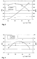
- FIG. 4 shows the effects explained above in a measurement data diagram.
- the meaning the axes and the curves is chosen similar to Figure 3, wherein However, attention is drawn to the different value ranges of the axes.
- FIG. 4 shows that using the strategy according to the invention in FIG considered time interval of the post-injection a much less critical Dependence of the exhaust gas temperature and the concentration of unburned hydrocarbons exists as without application of the invention.
- To negative effects of the throttling strategy of the invention on the To preclude driving behavior of the motor vehicle, may be higher when requested Accelerations or throttling at full-load operation reduced or completely canceled.
Landscapes
- Engineering & Computer Science (AREA)
- Chemical & Material Sciences (AREA)
- Combustion & Propulsion (AREA)
- Mechanical Engineering (AREA)
- General Engineering & Computer Science (AREA)
- Electrical Control Of Air Or Fuel Supplied To Internal-Combustion Engine (AREA)
- Control Of Throttle Valves Provided In The Intake System Or In The Exhaust System (AREA)
Abstract
Description
- kein Überschreiten der maximalen Temperaturgrenzen der Turbine und des Abgassystems;
- kein Überschreiten der maximal zulässigen freiwerdenden Reaktionswärme im Katalysator;
- kein Überschreiten der zulässigen Grenzwerte für Emissionen unverbrannter Kohlenwasserstoffe;
- kein Überschreiten der zulässigen Grenzwerte für das durch die Nacheinspritzung erzeugte zusätzliche Drehmoment.
Es zeigen:
- Figur 1
- schematisch die Komponenten eines Dieselmotors mit einer Abgasbehandlungseinrichtung,
- Figur 2
- qualitativ die Abhängigkeit der Wirkung der Nacheinspritzung von der Umgebungstemperatur,
- Figur 3
- die Abgastemperatur und die Kohlenwasserstoff-Konzentration im Abgas in Abhängigkeit vom Zeitpunkt der Nacheinspritzung beim Stand der Technik,
- Figur 4
- die Abgastemperatur und die Konzentration der Kohlenwasserstoffe im Abgas in Abhängigkeit vom Zeitpunkt der Nacheinspritzung bei Anwendung des erfindungsgemäßen Verfahrens.
Claims (10)
- Verfahren zur Regeneration einer Abgasbehandlungseinrichtung im Abgassystem einer Brennkraftmaschine, insbesondere eines Teilchenfilters (10) im Abgassystem eines Dieselmotors (5), wobei die Temperatur und/oder die Kohlenwasserstoff-Konzentration der Abgase durch die Nacheinspritzung von Kraftstoff im Arbeitstakt der Brennkraftmaschine erhöht werden,
dadurch gekennzeichnet, daß
die vorgegebenen Werte für den Ansaugdruck (MAP) und/oder den Luftmassenstrom (MAF) in Abhängigkeit von einer mit der Umgebungstemperatur korrelierten Größe derart verändert werden, daß durch die Nacheinspritzung stabile Werte der Abgastemperatur und/oder der Kohlenwasserstoff-Konzentration im Abgas erzielt werden. - Verfahren nach Anspruch 1,
dadurch gekennzeichnet, daß
die vorgegebenen Werte für den Ansaugdruck (MAP) und/oder den Luftmassenstrom (MAF) derart verändert werden, daß zum Zeitpunkt der Nacheinspritzung die Temperatur im Verbrennungsraum der Brennkraftmaschine (5) eine vorgegebene Schwelle nicht unterschreitet. - Verfahren nach Anspruch 1 oder 2,
dadurch gekennzeichnet, daß
die Umgebungstemperatur direkt gemessen wird. - Verfahren nach einem der Ansprüche 1 bis 3,
dadurch gekennzeichnet, daß
die vorgegebenen Werte für den Ansaugdruck (MAP) und/oder den Luftmassenstrom (MAF) um so stärker reduziert werden, je geringer die Umgebungstemperatur ist. - Verfahren nach einem der Ansprüche 1 bis 4,
dadurch gekennzeichnet, daß
die vorgegebenen Werte für den Ansaugdruck (MAP) und/oder den Luftmassenstrom (MAF) um so stärker reduziert werden, je geringer die Betriebstemperatur der Brennkraftmaschine (5) ist, wobei diese vorzugsweise über die Kühlmitteltemperatur erfaßt wird. - Verfahren nach einem der Ansprüche 1 bis 5,
dadurch gekennzeichnet, daß
die vorgegebenen Werte für den Ansaugdruck (MAP) und/oder den Luftmassenstrom (MAF) bei geringer Motorlast derart reduziert werden, daß durch die Nacheinspritzung stabile Werte der Abgastemperatur und/oder der Kohlenwasserstoff-Konzentration im Abgas erzielt werden. - Verfahren nach einem der Ansprüche 1 bis 6,
dadurch gekennzeichnet, daß
die vorgegebenen Werte für den Ansaugdruck (MAP) und/oder den Luftmassenstrom (MAF) in Abhängigkeit von der Motordrehzahl und der Motorlast oder dem gewünschten Motordrehmoment festgelegt werden. - Verfahren nach einem der Ansprüche 1 bis 7,
dadurch gekennzeichnet, daß
die Veränderung der vorgegebenen Werte für den Ansaugdruck (MAP) und/oder den Luftmassenstrom (MAF) reduziert oder aufgehoben wird, wenn eine hohe Beschleunigung und/oder Motorlast erforderlich ist. - Brennkraftmaschine, insbesondere Dieselmotor (5), mit einer im Abgassystem angeordneten Abgasbehandlungseinrichtung, insbesondere einem Teilchenfilter (10), und mit einer Steuereinrichtung zur Regeneration der Abgasbehandlungseinrichtung durch Erhöhung der Temperatur und/oder der Kohlenwasserstoff-Konzentration der Abgase, wobei die Steuereinrichtung derartig ausgebildet und mit Sensoren und Aktuatoren verbunden ist,
dadurch gekennzeichnet, daß
diese ein Verfahren nach einem der Ansprüche 1 bis 8 ausführen kann. - Brennkraftmaschine nach Anspruch 9,
dadurch gekennzeichnet, daß
die Steuereinrichtung mit einem Temperatursensor für die Umgebungstemperatur verbunden ist.
Priority Applications (3)
| Application Number | Priority Date | Filing Date | Title |
|---|---|---|---|
| DE50110758T DE50110758D1 (de) | 2001-09-25 | 2001-09-25 | Vorrichtung und Verfahren zur Regeneration einer Abgasbehandlungseinrichtung |
| EP01122902A EP1296050B1 (de) | 2001-09-25 | 2001-09-25 | Vorrichtung und Verfahren zur Regeneration einer Abgasbehandlungseinrichtung |
| US10/065,196 US6644020B2 (en) | 2001-09-25 | 2002-09-25 | Device and method for regenerating an exhaust gas aftertreatment device |
Applications Claiming Priority (1)
| Application Number | Priority Date | Filing Date | Title |
|---|---|---|---|
| EP01122902A EP1296050B1 (de) | 2001-09-25 | 2001-09-25 | Vorrichtung und Verfahren zur Regeneration einer Abgasbehandlungseinrichtung |
Publications (2)
| Publication Number | Publication Date |
|---|---|
| EP1296050A1 true EP1296050A1 (de) | 2003-03-26 |
| EP1296050B1 EP1296050B1 (de) | 2006-08-16 |
Family
ID=8178713
Family Applications (1)
| Application Number | Title | Priority Date | Filing Date |
|---|---|---|---|
| EP01122902A Expired - Lifetime EP1296050B1 (de) | 2001-09-25 | 2001-09-25 | Vorrichtung und Verfahren zur Regeneration einer Abgasbehandlungseinrichtung |
Country Status (3)
| Country | Link |
|---|---|
| US (1) | US6644020B2 (de) |
| EP (1) | EP1296050B1 (de) |
| DE (1) | DE50110758D1 (de) |
Cited By (5)
| Publication number | Priority date | Publication date | Assignee | Title |
|---|---|---|---|---|
| EP1533500A1 (de) * | 2003-11-19 | 2005-05-25 | Ford Global Technologies, LLC, A subsidary of Ford Motor Company | Verfahren und Vorrichtung zur Regeneration einer Abgasnachbehandlungseinrichtung |
| WO2007147720A1 (de) * | 2006-06-21 | 2007-12-27 | Robert Bosch Gmbh | Verfahren zum betreiben einer in einem abgasbereich einer brennkraftmaschine angeordneten abgasreinigungsanlage |
| WO2007115579A3 (en) * | 2006-04-12 | 2008-06-26 | Man Diesel As | A large turbocharged diesel engine with energy recovery arrangment |
| DE102004044732B4 (de) * | 2003-09-22 | 2012-04-26 | Toyota Jidosha Kabushiki Kaisha | Verfahren zum Einschränken einer unangemessen hohen Temperaturanhebung eines Filters in einem Verbrennungsmotor |
| DE102011111256B4 (de) * | 2010-09-09 | 2017-11-23 | GM Global Technology Operations LLC (n. d. Ges. d. Staates Delaware) | Verbesserte Fahrzeugbeschleunigung bei einem Luftdrosselungsmodus |
Families Citing this family (31)
| Publication number | Priority date | Publication date | Assignee | Title |
|---|---|---|---|---|
| US7293407B2 (en) * | 2000-06-21 | 2007-11-13 | Daimlerchrysler Ag | Method for operating a diesel engine |
| DE10203728A1 (de) * | 2002-01-30 | 2003-08-14 | Bosch Gmbh Robert | Elektronischer Vertauschschutz von Abgasmesssonden in einer abgasnachbehandelnden Brennkraftmaschine insbesondere eines Kraftfahrzeuges |
| JP2004176663A (ja) * | 2002-11-28 | 2004-06-24 | Honda Motor Co Ltd | 内燃機関の排気浄化装置 |
| DE10321105A1 (de) * | 2003-05-09 | 2004-12-02 | Emitec Gesellschaft Für Emissionstechnologie Mbh | Regeneration einer Partikelfalle |
| JP2007505266A (ja) | 2003-06-12 | 2007-03-08 | ドナルドソン カンパニー,インコーポレイティド | 排気システムの過渡的な流れ中に燃料を供給する方法 |
| US7409823B2 (en) | 2003-06-30 | 2008-08-12 | Delphi Technologies, Inc. | Method and apparatus for delivery of supplemental material to an exhaust gas feedstream with supplemental air assistance |
| US7152397B2 (en) * | 2003-11-07 | 2006-12-26 | Peugeot Citroen Automobiles Sa | Additional system for assisting regeneration of pollution control means of a motor vehicle |
| FR2862104B1 (fr) * | 2003-11-07 | 2006-02-17 | Peugeot Citroen Automobiles Sa | Systeme d'aide a la regeneration de moyens de depollution d'un moteur de vehicule automobile |
| GB2410313B (en) * | 2004-01-22 | 2007-08-08 | Ford Global Tech Llc | An engine and a method of making same |
| JP4314134B2 (ja) * | 2004-03-11 | 2009-08-12 | トヨタ自動車株式会社 | 内燃機関排気浄化装置の粒子状物質再生制御装置 |
| WO2006023079A2 (en) * | 2004-08-20 | 2006-03-02 | Southwest Research Institute | Method for rich pulse control of diesel engines |
| CA2598862C (en) * | 2005-02-28 | 2012-07-17 | Yanmar Co., Ltd. | Exhaust gas purification apparatus, internal combustion engine comprising the same, and particulate filter restoring method |
| JP4424242B2 (ja) * | 2005-03-30 | 2010-03-03 | トヨタ自動車株式会社 | 内燃機関の混合気状態推定装置、及びエミッション発生量推定装置 |
| US7343735B2 (en) * | 2005-05-02 | 2008-03-18 | Cummins, Inc. | Apparatus and method for regenerating an exhaust gas aftertreatment component of an internal combustion engine |
| US7107764B1 (en) | 2005-06-15 | 2006-09-19 | Caterpillar Inc. | Exhaust treatment system |
| US20070068141A1 (en) * | 2005-06-15 | 2007-03-29 | Opris Cornelius N | Exhaust treatment system |
| US7444815B2 (en) * | 2005-12-09 | 2008-11-04 | Deere & Company | EGR system for high EGR rates |
| US8322129B2 (en) * | 2006-02-16 | 2012-12-04 | Cummins, Inc. | Method for controlling turbine outlet temperatures in a diesel engine |
| US20070186538A1 (en) * | 2006-02-16 | 2007-08-16 | Dollmeyer Thomas A | Method for controlling turbine outlet temperatures in a diesel engine at idle and light load conditions |
| US7762060B2 (en) | 2006-04-28 | 2010-07-27 | Caterpillar Inc. | Exhaust treatment system |
| US20080078170A1 (en) * | 2006-09-29 | 2008-04-03 | Gehrke Christopher R | Managing temperature in an exhaust treatment system |
| US20080163610A1 (en) * | 2007-01-05 | 2008-07-10 | Matthew Thomas Baird | Method and system for regenerating exhaust system filtering and catalyst components using variable high engine idle |
| US20090113880A1 (en) * | 2007-11-01 | 2009-05-07 | Clausen Michael D | Diesel engine |
| US8061127B2 (en) * | 2008-04-29 | 2011-11-22 | Cummins, Inc. | Thermal management of diesel particulate filter regeneration events |
| US8499550B2 (en) * | 2008-05-20 | 2013-08-06 | Cummins Ip, Inc. | Apparatus, system, and method for controlling particulate accumulation on an engine filter during engine idling |
| GB0811144D0 (en) * | 2008-06-18 | 2008-07-23 | Parker Hannifin U K Ltd | A liquid drain system |
| DE102008058010B4 (de) * | 2008-11-19 | 2015-03-12 | Continental Automotive Gmbh | Verfahren und Vorrichtung zum Betreiben einer Brennkraftmaschine |
| US20110289902A1 (en) * | 2010-05-27 | 2011-12-01 | International Engine Intellectual Property Company , Llc | Method for operating an exhaust valve for diesel particulate filter regeneration |
| US8528323B2 (en) * | 2010-06-30 | 2013-09-10 | GM Global Technology Operations LLC | System and method for particulate matter filter regeneration using a catalytic converter as a combustor |
| JP5986736B2 (ja) * | 2011-11-16 | 2016-09-06 | 三菱重工業株式会社 | 内燃機関の排気浄化システム |
| EP2647815B1 (de) * | 2012-04-05 | 2015-08-05 | Delphi International Operations Luxembourg S.à r.l. | NOx-Falle für Magergemischverbrennungsentschwefelungsprozess |
Citations (4)
| Publication number | Priority date | Publication date | Assignee | Title |
|---|---|---|---|---|
| FR2774427A1 (fr) * | 1998-02-02 | 1999-08-06 | Peugeot | Systeme d'aide a la regeneration d'un filtre a particules integre dans une ligne d'echappement de moteur diesel notamment pour vehicule automobile |
| DE19927485A1 (de) * | 1998-08-04 | 2000-02-24 | Toyota Motor Co Ltd | Kraftstoffeinspritzsteuervorrichtung für einen Verbrennungsmotor |
| JP2000064889A (ja) * | 1998-08-18 | 2000-02-29 | Nissan Motor Co Ltd | 内燃機関の排気浄化装置 |
| EP1035313A2 (de) * | 1999-03-05 | 2000-09-13 | Bayerische Motoren Werke Aktiengesellschaft | Verfahren und Vorrichtung zur Abgastemperaturerhöhung |
Family Cites Families (19)
| Publication number | Priority date | Publication date | Assignee | Title |
|---|---|---|---|---|
| US4211075A (en) | 1978-10-19 | 1980-07-08 | General Motors Corporation | Diesel engine exhaust particulate filter with intake throttling incineration control |
| US4270936A (en) | 1980-01-18 | 1981-06-02 | General Motors Corporation | Coiled fibrous metallic material and coating for diesel exhaust particulate trap |
| JPS5855020A (ja) | 1981-09-29 | 1983-04-01 | Toyota Motor Corp | 排出ガスフイルタおよび微粒子処理系 |
| JPS59122721A (ja) | 1982-12-29 | 1984-07-16 | Toyota Motor Corp | フイルタ再生装置 |
| US4686827A (en) | 1983-02-03 | 1987-08-18 | Ford Motor Company | Filtration system for diesel engine exhaust-II |
| JPS59150921A (ja) * | 1983-02-16 | 1984-08-29 | Toyota Motor Corp | デイ−ゼルエンジンの排気浄化装置におけるトラツプ再生装置 |
| JPS6043113A (ja) * | 1983-08-18 | 1985-03-07 | Mitsubishi Motors Corp | デイ−ゼル排出ガス浄化装置 |
| US4656155A (en) | 1985-07-25 | 1987-04-07 | Atlantic Richfield Company | Reducible metal oxide compositions containing zirconium oxide, yttrium oxide and an alkali metal component |
| US5014511A (en) | 1986-04-09 | 1991-05-14 | Ford Motor Company | Filtration system for diesel engine exhaust-II |
| US4902487A (en) | 1988-05-13 | 1990-02-20 | Johnson Matthey, Inc. | Treatment of diesel exhaust gases |
| DE3912301A1 (de) | 1989-04-14 | 1990-10-25 | Daimler Benz Ag | Verfahren zur regeneration eines in der abgasleitung einer luftverdichtenden brennkraftmaschine angeordneten russpartikelfilters |
| JPH03202609A (ja) | 1989-12-28 | 1991-09-04 | Nissan Motor Co Ltd | エンジンの排気浄化装置 |
| IT1266889B1 (it) | 1994-07-22 | 1997-01-21 | Fiat Ricerche | Metodo di autoinnesco della rigenerazione in un filtro particolato per un motore diesel con sistema d'iniezione a collettore comune. |
| JP3089989B2 (ja) | 1995-05-18 | 2000-09-18 | トヨタ自動車株式会社 | ディーゼル機関の排気浄化装置 |
| JP3414303B2 (ja) * | 1998-03-17 | 2003-06-09 | 日産自動車株式会社 | 直噴火花点火式内燃機関の制御装置 |
| JP3607980B2 (ja) * | 1999-12-16 | 2005-01-05 | トヨタ自動車株式会社 | 内燃機関 |
| US6304815B1 (en) * | 2000-03-29 | 2001-10-16 | Ford Global Technologies, Inc. | Method for controlling an exhaust gas temperature of an engine for improved performance of exhaust aftertreatment systems |
| US6490857B2 (en) * | 2000-06-29 | 2002-12-10 | Toyota Jidosha Kabushiki Kaisha | Device for purifying the exhaust gas of an internal combustion engine |
| JP2002188432A (ja) * | 2000-12-19 | 2002-07-05 | Isuzu Motors Ltd | ディーゼルエンジンの排気浄化装置 |
-
2001
- 2001-09-25 DE DE50110758T patent/DE50110758D1/de not_active Expired - Lifetime
- 2001-09-25 EP EP01122902A patent/EP1296050B1/de not_active Expired - Lifetime
-
2002
- 2002-09-25 US US10/065,196 patent/US6644020B2/en not_active Expired - Lifetime
Patent Citations (4)
| Publication number | Priority date | Publication date | Assignee | Title |
|---|---|---|---|---|
| FR2774427A1 (fr) * | 1998-02-02 | 1999-08-06 | Peugeot | Systeme d'aide a la regeneration d'un filtre a particules integre dans une ligne d'echappement de moteur diesel notamment pour vehicule automobile |
| DE19927485A1 (de) * | 1998-08-04 | 2000-02-24 | Toyota Motor Co Ltd | Kraftstoffeinspritzsteuervorrichtung für einen Verbrennungsmotor |
| JP2000064889A (ja) * | 1998-08-18 | 2000-02-29 | Nissan Motor Co Ltd | 内燃機関の排気浄化装置 |
| EP1035313A2 (de) * | 1999-03-05 | 2000-09-13 | Bayerische Motoren Werke Aktiengesellschaft | Verfahren und Vorrichtung zur Abgastemperaturerhöhung |
Non-Patent Citations (1)
| Title |
|---|
| PATENT ABSTRACTS OF JAPAN vol. 2000, no. 05 14 September 2000 (2000-09-14) * |
Cited By (5)
| Publication number | Priority date | Publication date | Assignee | Title |
|---|---|---|---|---|
| DE102004044732B4 (de) * | 2003-09-22 | 2012-04-26 | Toyota Jidosha Kabushiki Kaisha | Verfahren zum Einschränken einer unangemessen hohen Temperaturanhebung eines Filters in einem Verbrennungsmotor |
| EP1533500A1 (de) * | 2003-11-19 | 2005-05-25 | Ford Global Technologies, LLC, A subsidary of Ford Motor Company | Verfahren und Vorrichtung zur Regeneration einer Abgasnachbehandlungseinrichtung |
| WO2007115579A3 (en) * | 2006-04-12 | 2008-06-26 | Man Diesel As | A large turbocharged diesel engine with energy recovery arrangment |
| WO2007147720A1 (de) * | 2006-06-21 | 2007-12-27 | Robert Bosch Gmbh | Verfahren zum betreiben einer in einem abgasbereich einer brennkraftmaschine angeordneten abgasreinigungsanlage |
| DE102011111256B4 (de) * | 2010-09-09 | 2017-11-23 | GM Global Technology Operations LLC (n. d. Ges. d. Staates Delaware) | Verbesserte Fahrzeugbeschleunigung bei einem Luftdrosselungsmodus |
Also Published As
| Publication number | Publication date |
|---|---|
| US20030056498A1 (en) | 2003-03-27 |
| DE50110758D1 (de) | 2006-09-28 |
| EP1296050B1 (de) | 2006-08-16 |
| US6644020B2 (en) | 2003-11-11 |
Similar Documents
| Publication | Publication Date | Title |
|---|---|---|
| EP1296050B1 (de) | Vorrichtung und Verfahren zur Regeneration einer Abgasbehandlungseinrichtung | |
| DE60108298T2 (de) | Brennkraftmaschine und Verfahren zur Steuerung | |
| DE60306743T2 (de) | Motorsteuerung zum Erreichen einer schnelleren Erwärmung des Katalysators | |
| DE69820167T2 (de) | Steuerung für Verbrennung und Abgasrückführung in einer Brennkraftmaschine | |
| DE60311758T2 (de) | Vorrichtung zur Reinigung von Abgas einer Brennkraftmaschine | |
| EP1203869B1 (de) | Regelungsanordnung und Verfahren zur Unterbrechung der Regeneration eines Partikelfilters eines Dieselmotors | |
| DE19924274B4 (de) | System und Verfahren zum Steuern eines Turboladers zur Maximierung der Leistung eines Verbrennungsmotors | |
| DE102008000069B4 (de) | Vorrichtung zum Steuern einer Einspritzung von Kraftstoff in eine Kraftmaschine und Vorrichtung zum Steuern einer Verbrennung in einer Kraftmaschine | |
| DE102011011371B4 (de) | Adaptive Dieselmotorsteuerung bei Cetanzahlschwankungen | |
| DE60108006T2 (de) | Brennkraftmaschine und Methode für Abgasrückführung | |
| WO2005005813A2 (de) | Brennkraftmaschine | |
| DE69820401T2 (de) | Brennkraftmaschine mit Kompressionszündung | |
| DE102011109482A1 (de) | Modellbasierte Methodik zur Steuerung einer Übergangs-Zeiteinstellung der Kraftstoffeinspritzung | |
| DE102013208047B4 (de) | Adaptive Regenerierung einer Abgasnachbehandlungseinrichtung in Ansprechen auf eine Biodiesel-Kraftstoffmischung | |
| DE60226204T2 (de) | Vorrichtung zur Steuerung der Abgasabgabe eines Motors | |
| DE102008003581A1 (de) | Verfahren und Vorrichtung zur Verringerung der Abgastemperatur bei einem Kraftfahrzeug | |
| DE112007000409B4 (de) | Verfahren zum Steuern von Turbinenauslasstemperaturen in einem Dieselmotor | |
| WO2004051067A1 (de) | Verfahren zum steuern einer mit kraftstoffdirekteinspritzung arbeitenden brennkraftmaschine | |
| WO2012080000A1 (de) | Verfahren und vorrichtung zum durchführen einer nullpunktadaption einer lambdasonde eines verbrennungsmotors | |
| DE19951096A1 (de) | Motorregelsystem für einen mittels Abgasturbolader aufgeladenen Dieselmotor | |
| DE102013207819B4 (de) | Verfahren zum Betreiben eines Kompressionszündungsmotors | |
| DE102010002606A1 (de) | Verfahren und Vorrichtung zur Regelung der Regeneration eines Partikelfilters | |
| DE112018002095T5 (de) | Abgasbehandlungsvorrichtung für Verbrennungskraftmaschine | |
| EP1368561B1 (de) | Verfahren und vorrichtung zur steuerung einer brennkraftmaschine | |
| DE112019003685T5 (de) | Verbrennungsmotor-steuervorrichtung und verbrennungsmotor-steuerverfahren |
Legal Events
| Date | Code | Title | Description |
|---|---|---|---|
| PUAI | Public reference made under article 153(3) epc to a published international application that has entered the european phase |
Free format text: ORIGINAL CODE: 0009012 |
|
| AK | Designated contracting states |
Kind code of ref document: A1 Designated state(s): AT BE CH CY DE DK ES FI FR GB GR IE IT LI LU MC NL PT SE TR Designated state(s): AT BE CH CY DE DK ES FI FR GB GR IE IT LI LU MC NL PT SE TR |
|
| AX | Request for extension of the european patent |
Extension state: AL LT LV MK RO SI |
|
| 17P | Request for examination filed |
Effective date: 20030926 |
|
| AKX | Designation fees paid |
Designated state(s): DE FR GB |
|
| GRAP | Despatch of communication of intention to grant a patent |
Free format text: ORIGINAL CODE: EPIDOSNIGR1 |
|
| RAP1 | Party data changed (applicant data changed or rights of an application transferred) |
Owner name: FORD GLOBAL TECHNOLOGIES, LLC. |
|
| GRAS | Grant fee paid |
Free format text: ORIGINAL CODE: EPIDOSNIGR3 |
|
| GRAA | (expected) grant |
Free format text: ORIGINAL CODE: 0009210 |
|
| AK | Designated contracting states |
Kind code of ref document: B1 Designated state(s): DE FR GB |
|
| REG | Reference to a national code |
Ref country code: GB Ref legal event code: FG4D Free format text: NOT ENGLISH |
|
| REF | Corresponds to: |
Ref document number: 50110758 Country of ref document: DE Date of ref document: 20060928 Kind code of ref document: P |
|
| GBT | Gb: translation of ep patent filed (gb section 77(6)(a)/1977) |
Effective date: 20061103 |
|
| ET | Fr: translation filed | ||
| PLBE | No opposition filed within time limit |
Free format text: ORIGINAL CODE: 0009261 |
|
| STAA | Information on the status of an ep patent application or granted ep patent |
Free format text: STATUS: NO OPPOSITION FILED WITHIN TIME LIMIT |
|
| 26N | No opposition filed |
Effective date: 20070518 |
|
| REG | Reference to a national code |
Ref country code: FR Ref legal event code: PLFP Year of fee payment: 15 |
|
| REG | Reference to a national code |
Ref country code: FR Ref legal event code: PLFP Year of fee payment: 16 |
|
| REG | Reference to a national code |
Ref country code: FR Ref legal event code: PLFP Year of fee payment: 17 |
|
| REG | Reference to a national code |
Ref country code: FR Ref legal event code: PLFP Year of fee payment: 18 |
|
| PGFP | Annual fee paid to national office [announced via postgrant information from national office to epo] |
Ref country code: DE Payment date: 20200812 Year of fee payment: 20 Ref country code: GB Payment date: 20200828 Year of fee payment: 20 Ref country code: FR Payment date: 20200814 Year of fee payment: 20 |
|
| REG | Reference to a national code |
Ref country code: DE Ref legal event code: R071 Ref document number: 50110758 Country of ref document: DE |
|
| REG | Reference to a national code |
Ref country code: GB Ref legal event code: PE20 Expiry date: 20210924 |
|
| PG25 | Lapsed in a contracting state [announced via postgrant information from national office to epo] |
Ref country code: GB Free format text: LAPSE BECAUSE OF EXPIRATION OF PROTECTION Effective date: 20210924 |