EP1296085A2 - Système de commande de l'accouplement de pontage d'un convertisseur de couple - Google Patents
Système de commande de l'accouplement de pontage d'un convertisseur de couple Download PDFInfo
- Publication number
- EP1296085A2 EP1296085A2 EP02256466A EP02256466A EP1296085A2 EP 1296085 A2 EP1296085 A2 EP 1296085A2 EP 02256466 A EP02256466 A EP 02256466A EP 02256466 A EP02256466 A EP 02256466A EP 1296085 A2 EP1296085 A2 EP 1296085A2
- Authority
- EP
- European Patent Office
- Prior art keywords
- lockup
- coasting
- slip
- torque converter
- air conditioner
- Prior art date
- Legal status (The legal status is an assumption and is not a legal conclusion. Google has not performed a legal analysis and makes no representation as to the accuracy of the status listed.)
- Withdrawn
Links
- 230000000994 depressogenic effect Effects 0.000 claims abstract description 9
- 239000000446 fuel Substances 0.000 description 36
- 230000005540 biological transmission Effects 0.000 description 27
- 230000009467 reduction Effects 0.000 description 19
- 230000006870 function Effects 0.000 description 14
- 230000000694 effects Effects 0.000 description 8
- 230000003247 decreasing effect Effects 0.000 description 5
- 238000011084 recovery Methods 0.000 description 5
- 230000008878 coupling Effects 0.000 description 4
- 238000010168 coupling process Methods 0.000 description 4
- 238000005859 coupling reaction Methods 0.000 description 4
- 238000012546 transfer Methods 0.000 description 4
- 230000035939 shock Effects 0.000 description 3
- 230000032683 aging Effects 0.000 description 2
- 230000008859 change Effects 0.000 description 2
- 230000000881 depressing effect Effects 0.000 description 2
- 239000012530 fluid Substances 0.000 description 2
- 230000002159 abnormal effect Effects 0.000 description 1
- 238000013459 approach Methods 0.000 description 1
- 230000002457 bidirectional effect Effects 0.000 description 1
- 238000004891 communication Methods 0.000 description 1
- 230000000593 degrading effect Effects 0.000 description 1
- 238000001514 detection method Methods 0.000 description 1
- 238000002347 injection Methods 0.000 description 1
- 239000007924 injection Substances 0.000 description 1
- 238000011835 investigation Methods 0.000 description 1
- 238000000034 method Methods 0.000 description 1
- 238000012986 modification Methods 0.000 description 1
- 230000004048 modification Effects 0.000 description 1
- 230000002265 prevention Effects 0.000 description 1
- 238000011160 research Methods 0.000 description 1
Images


Classifications
-
- F—MECHANICAL ENGINEERING; LIGHTING; HEATING; WEAPONS; BLASTING
- F16—ENGINEERING ELEMENTS AND UNITS; GENERAL MEASURES FOR PRODUCING AND MAINTAINING EFFECTIVE FUNCTIONING OF MACHINES OR INSTALLATIONS; THERMAL INSULATION IN GENERAL
- F16H—GEARING
- F16H61/00—Control functions within control units of change-speed- or reversing-gearings for conveying rotary motion ; Control of exclusively fluid gearing, friction gearing, gearings with endless flexible members or other particular types of gearing
- F16H61/14—Control of torque converter lock-up clutches
- F16H61/143—Control of torque converter lock-up clutches using electric control means
-
- F—MECHANICAL ENGINEERING; LIGHTING; HEATING; WEAPONS; BLASTING
- F16—ENGINEERING ELEMENTS AND UNITS; GENERAL MEASURES FOR PRODUCING AND MAINTAINING EFFECTIVE FUNCTIONING OF MACHINES OR INSTALLATIONS; THERMAL INSULATION IN GENERAL
- F16H—GEARING
- F16H61/00—Control functions within control units of change-speed- or reversing-gearings for conveying rotary motion ; Control of exclusively fluid gearing, friction gearing, gearings with endless flexible members or other particular types of gearing
- F16H61/14—Control of torque converter lock-up clutches
-
- F—MECHANICAL ENGINEERING; LIGHTING; HEATING; WEAPONS; BLASTING
- F16—ENGINEERING ELEMENTS AND UNITS; GENERAL MEASURES FOR PRODUCING AND MAINTAINING EFFECTIVE FUNCTIONING OF MACHINES OR INSTALLATIONS; THERMAL INSULATION IN GENERAL
- F16H—GEARING
- F16H59/00—Control inputs to control units of change-speed- or reversing-gearings for conveying rotary motion
- F16H59/14—Inputs being a function of torque or torque demand
- F16H59/18—Inputs being a function of torque or torque demand dependent on the position of the accelerator pedal
- F16H2059/186—Coasting
-
- F—MECHANICAL ENGINEERING; LIGHTING; HEATING; WEAPONS; BLASTING
- F16—ENGINEERING ELEMENTS AND UNITS; GENERAL MEASURES FOR PRODUCING AND MAINTAINING EFFECTIVE FUNCTIONING OF MACHINES OR INSTALLATIONS; THERMAL INSULATION IN GENERAL
- F16H—GEARING
- F16H61/00—Control functions within control units of change-speed- or reversing-gearings for conveying rotary motion ; Control of exclusively fluid gearing, friction gearing, gearings with endless flexible members or other particular types of gearing
- F16H61/04—Smoothing ratio shift
- F16H2061/0425—Bridging torque interruption
-
- F—MECHANICAL ENGINEERING; LIGHTING; HEATING; WEAPONS; BLASTING
- F16—ENGINEERING ELEMENTS AND UNITS; GENERAL MEASURES FOR PRODUCING AND MAINTAINING EFFECTIVE FUNCTIONING OF MACHINES OR INSTALLATIONS; THERMAL INSULATION IN GENERAL
- F16H—GEARING
- F16H61/00—Control functions within control units of change-speed- or reversing-gearings for conveying rotary motion ; Control of exclusively fluid gearing, friction gearing, gearings with endless flexible members or other particular types of gearing
- F16H61/14—Control of torque converter lock-up clutches
- F16H61/143—Control of torque converter lock-up clutches using electric control means
- F16H2061/145—Control of torque converter lock-up clutches using electric control means for controlling slip, e.g. approaching target slip value
-
- F—MECHANICAL ENGINEERING; LIGHTING; HEATING; WEAPONS; BLASTING
- F16—ENGINEERING ELEMENTS AND UNITS; GENERAL MEASURES FOR PRODUCING AND MAINTAINING EFFECTIVE FUNCTIONING OF MACHINES OR INSTALLATIONS; THERMAL INSULATION IN GENERAL
- F16H—GEARING
- F16H2342/00—Calibrating
- F16H2342/04—Calibrating engagement of friction elements
- F16H2342/044—Torque transmitting capability
-
- F—MECHANICAL ENGINEERING; LIGHTING; HEATING; WEAPONS; BLASTING
- F16—ENGINEERING ELEMENTS AND UNITS; GENERAL MEASURES FOR PRODUCING AND MAINTAINING EFFECTIVE FUNCTIONING OF MACHINES OR INSTALLATIONS; THERMAL INSULATION IN GENERAL
- F16H—GEARING
- F16H59/00—Control inputs to control units of change-speed- or reversing-gearings for conveying rotary motion
- F16H59/14—Inputs being a function of torque or torque demand
- F16H59/18—Inputs being a function of torque or torque demand dependent on the position of the accelerator pedal
- F16H59/22—Idle position
-
- F—MECHANICAL ENGINEERING; LIGHTING; HEATING; WEAPONS; BLASTING
- F16—ENGINEERING ELEMENTS AND UNITS; GENERAL MEASURES FOR PRODUCING AND MAINTAINING EFFECTIVE FUNCTIONING OF MACHINES OR INSTALLATIONS; THERMAL INSULATION IN GENERAL
- F16H—GEARING
- F16H59/00—Control inputs to control units of change-speed- or reversing-gearings for conveying rotary motion
- F16H59/50—Inputs being a function of the status of the machine, e.g. position of doors or safety belts
Definitions
- the present invention relates to a lockup control system for a torque converter in an automatic transmission of a vehicle. More particularly, the present invention relates to a lockup control system adapted to suitably control the lockup capacity of the torque converter during coasting, or inertial traveling, of the vehicle with the accelerator pedal released.
- An automatic transmission inclusive of a continuously variable transmission (CVT) is generally provided with a torque converter in the power train, for multiplying torque and/or absorbing torque fluctuations.
- a torque converter conducts power transmission between input and output elements via an operating fluid, and thus suffers from relatively low transmission efficiency and unsatisfactory fuel consumption.
- it is a customary measure to adopt a lockup type torque converter wherein the input and output elements can be directly coupled by engaging a lockup clutch in vehicle traveling conditions wherein torque multiplying function and/or torque-fluctuation absorbing function are not required.
- a fuel cutoff device for stopping fuel supply to the engine during coasting of the vehicle, in which an accelerator pedal is released and the driving force from the engine is not required.
- a fuel cutoff device has a fuel recovery function for resuming fuel supply to the engine, so as to prevent engine stalling upon decrease in the engine revolution speed or in the vehicle speed down to a predetermined value.
- U.S. Patent No. 5,953,043 discloses a lockup control system adapted to control engagement of the lockup clutch of the torque converter, wherein the torque converter can be locked-up with a required minimum lockup capacity or minimum lockup pressure required for achieving the slip restricted state during coasting of the vehicle.
- the required minimum lockup capacity of the lockup clutch changes significantly, depending upon the load condition of air conditioner provided for the vehicle, since the air conditioner includes a compressor that is driven by the engine and thus operatively coupled to driving wheels of the vehicle.
- the required minimum lockup capacity so as to be optimized when the air conditioner is under high load condition or when a reverse torque (so-called coasting torque) which is transmitted from the driving wheels toward the engine during coasting of the vehicle is high.
- the required minimum lockup capacity so determined would be excessively high when the coasting torque is low or when the air conditioner is under low load condition, such that cancellation of slip restriction or disengagement of the lockup clutch required upon wheel locking cannot be performed in a timely manner, thereby failing to achieve the primary function of engine stalling prevention.
- the required minimum lockup capacity is determined so as to be optimized when the air conditioner is under low load condition or when the coasting torque is low, the required minimum lockup capacity would be insufficient when the coasting torque is high or when the air conditioner is under high load condition, giving rise to a situation wherein the engine rotation cannot be maintained by the driving wheels and tends to be lowered too quickly, thereby failing to achieve the primary function to extend the duration of fuel cutoff for improving the fuel consumption of the vehicle.
- the present invention is based on a novel recognition obtained from thorough research and investigations, that it would be highly effective to control the coasting lockup capacity of the torque converter in an optimized manner, depending upon the load state of the air conditioner.
- the present invention provides a lockup control system for a torque converter of a vehicle that is equipped with an air conditioner, wherein the lockup control system is adapted to maintain a coasting slip restricted state of the torque converter even during coasting of the vehicle with an accelerator pedal released, for restricting slip rotation between input and output elements of the torque converter.
- the coasting slip restricted state is achieved by a coasting lockup capacity that is lower than a lockup capacity of the torque converter in a driving condition of the vehicle with the accelerator pedal depressed.
- the coasting lockup capacity is controlled according to an operation load of the air conditioner and is increased as the operation load of the air conditioner increases.
- the torque converter is maintained in the slip restricted state even during coasting of the vehicle, it is possible to delay the lowering of the engine revolution speed by the drive wheels and to enhance the fuel saving effect by extending the duration of fuel cutoff.
- the coasting slip restricted state is achieved by a coasting lockup capacity that is smaller than a lockup capacity of the torque converter in a driving condition of the vehicle with the accelerator pedal depressed, it is possible to quickly cancel the slip restriction of the torque converter upon wheel locking, and thereby avoid engine stalling that may otherwise occur as a result of wheel locking.
- the coasting lockup capacity is controlled corresponding to the operation load of the air conditioner, it is possible to eliminate the above-mentioned problems arising from inadequately determined coasting lockup capacity of the torque converter, as follows.
- the coasting lockup capacity is correspondingly increased to a level sufficient to prevent slipping of the torque converter under the coasting torque, making it possible to ensure reverse driving of the engine by the driving wheels so as to delay lowering of the engine revolution speed and thereby achieve the primary function of extending the duration of fuel cutoff to enhance the fuel saving effect.
- the coasting lockup capacity is correspondingly decreased to a level that allows a timely lockup cancellation upon wheel locking, thereby achieving the primary function to prevent engine stalling. Furthermore, the decreased coasting lockup capacity serves to prevent engine torque fluctuation from being directly transmitted to the driving wheels, thereby preventing generation of shocks in the power train and maintaining the driving comfort.
- the slip restricted state of the torque converter is a lockup state in which the slip rotation between the input and output elements of the torque converter is set to zero
- the coasting lockup capacity is a required minimum lockup capacity obtained by adding an estimated value for bringing the slip rotation to zero, to a lockup capacity with which the slip rotation becomes a predetermined slight-slip rotation.
- the lockup capacity with which the slip rotation becomes the predetermined slight-slip rotation may be stored as a learned value for each operation load of the air conditioner, so as to be used as basis for calculation of the required minimum lockup capacity. In this way, the lockup control of the torque converter can be performed in optimum manner by the learning-control.
- the slip restricted state of the torque converter is a slip controlled state in which the slip rotation between the input and output elements of the torque converter is controlled to be a slip rotation other than zero, corresponding to the operating state of the vehicle, and the coasting lockup capacity is increased corresponding to increase in operation load of the air conditioner, when a coasting slip control of the torque converter with the accelerator pedal released is transferred from a driving slip control with the accelerator pedal depressed.
- the torque converter is kept in the slip controlled state corresponding to the vehicle operating state even during coasting, it is possible to delay the lowering of the engine revolution by the drive wheels and to enhance the fuel saving effect by extending the duration of fuel cutoff.
- the slip controlled state is achieved by a coasting lockup capacity that is smaller than a lockup capacity when the accelerator pedal is depressed, the slip restriction upon wheel locking due to sudden braking can be quickly cancelled, thereby avoiding engine stalling due to the wheel locking.
- the coasting lockup capacity is increased for higher load corresponding to the operation load of the air conditioner, it is possible to extend the duration of fuel cutoff and to quickly cancel the slip controlled state upon wheel locking, thereby prevent engine stalling.
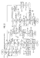
- FIG. 1 is a schematic view showing a power train of a vehicle provided with a lockup control system according to the present invention.
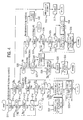
- FIG. 2 is a flowchart of the coasting lockup control executed by a lockup control system according to a first embodiment of the present invention.
- FIG. 3 is an operational time chart of the coast lockup control shown in FIG. 2.
- FIG. 4 is a flowchart of the coasting lockup control executed by a lockup control system according to a second embodiment of the present invention.
- FIG. 5 is a flowchart of a coasting slip control executed by a lockup control system according to a third embodiment of the present invention.
- FIG. 6 is a flowchart of a coasting slip control executed by a lockup control system according to a fourth embodiment of the present invention.
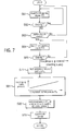
- FIG. 7 is a flowchart of a coasting slip control executed by a lockup control system according to a fifth embodiment of the present invention.
- a power train of a vehicle is shown in FIG. 1 and includes an engine 1, an automatic transmission 2, and a torque converter 3 for drivingly coupling them.
- the torque converter 3 includes a lockup clutch (not shown) to which the lockup control system according to the present invention is applicable.
- the engine 1 includes a throttle valve 5 having an opening degree that is increased by depressing an accelerator pedal 4, so as to suck an amount of air corresponding to the opening degree and the engine revolution speed, via air cleaner 6.
- the engine 1 further includes a group of injectors 7 provided for respective engine cylinders, an ignition device 8, as well as an engine controller 9 for controlling the injectors 7 and the ignition device 8.
- the engine controller 9 is supplied with a signal from a suction amount sensor 11 for detecting air suction amount Q sucked into the engine 1, and a signal I from a coasting switch 12 that is turned ON upon releasing the accelerator pedal 4.
- the engine controller 9 Based on the input information, the engine controller 9 conducts fuel injection controls so that predetermined amount of fuel is injected from the injectors 7 to predetermined cylinders, respectively, depending on the operation state of the engine 1, and also conducts fuel-cutoff for stopping the fuel supply to the engine 1 or fuel recovery for resuming the fuel supply.
- the engine controller 9 further controls the ignition device 8 so as to ignite spark plugs for predetermined engine cylinders at predetermined timings, depending on the operating state of the engine 1 based on the input information. In this way, the engine 1 is properly operated and subjected to fuel cutoff during coasting of the vehicle with the accelerator pedal 4 released.
- the engine controller 9 further conducts fuel recovery when the engine revolution speed is lowered, or reduced, to a predetermined value, so as to inject a predetermined amount of fuel to the predetermined cylinders from the respective injectors 7, and to thereby prevent engine stalling.
- the rotational power output from the engine 1 is transmitted to the automatic transmission 2 through the torque converter 3.
- the automatic transmission 2 has multiple gear ranges to be selected depending upon combined ON/OFF states of shift solenoids 15, 16 within a control valve 13.
- the input rotation speed of the automatic transmission 2 is changed into the output rotation speed by a gear ratio corresponding to the selected gear range, and the output rotation is transmitted from an output shaft 14 to driving wheels 18 so as to drive the vehicle.
- the torque converter 3 includes an engine-driven input element or a pump impeller and an output element or a turbine runner, and transmits the rotation of the input element to the output element via internal operating fluid while multiplying torque and absorbing torque fluctuation (converter mode), so that the turbine rotation is transmitted to the automatic transmission 2. Furthermore, the torque converter 3 is provided with a built-in lockup clutch for mechanically coupling the input and output elements with each other to restrict slip rotation therebetween, including a fully locked state in which the slip rotation is zero.
- the engaging pressure or lockup pressure of the lockup clutch is determined by a driving duty D of a lockup solenoid 17 within the control valve 13, so that the slip rotation of the torque converter 3 is restricted by coupling the input and output elements of the torque converter with each other under an engaging force or lockup capacity corresponding to the engaging pressure.
- the ON/OFF states of the shift solenoids 15, 16 and the driving duty D of the lockup solenoid 17 are controlled by a transmission controller 21.
- the transmission controller 21 is supplied with various input signals, including the signal I from the coasting switch 12, a signal from a throttle opening degree sensor 22 for detecting the throttle opening degree TVO, a signal from an impeller rotation sensor 23 for detecting the input rotation speed Ni of the torque converter 3, a signal from a turbine rotation sensor 24 for detecting the output rotation speed Nt of the torque converter 3, a signal from a transmission output rotation sensor 25 for detecting the rotation speed No of the transmission output shaft 14, a signal B from a brake switch 27 to be turned ON upon depressing a brake pedal 26, and an ON/OFF signal of an air conditioner switch 28 or a signal from a compressor pressure sensor 29 for detecting a compressor internal pressure P AC of the air conditioner .
- the transmission controller 21 conducts shift control of the automatic transmission 2 in the following manner, by known calculations based on the above-mentioned input information. First, a gear range of the automatic transmission 2 preferred for the current vehicle operating state is retrieved from a scheduled shift map, based on a vehicle speed VSP obtained from the transmission output rotation No and based on the throttle opening degree TVO. Further, the shift solenoids 15, 16 are switched on or off, so as to conduct gear change to the preferred gear range.
- the transmission controller 21 further determines from the input information whether or not the automatic transmission 2 is in a lockup region which does not require torque multiplying function or and torque fluctuation absorbing function of the torque converter 3. If it is determined that the automatic transmission 2 is in a lockup region, the transmission controller 21 conducts a duty control (D) of the lockup solenoid 17 to bring the torque converter 3 into a lockup state where the input and output elements are directly coupled by engagement of the lockup clutch under an increased lockup pressure.
- D duty control
- the transmission controller 21 conducts a duty control of the lockup solenoid 17 to bring the torque converter 3 into a converter state where the direct coupling between the input and output elements is terminated by disengaging the lockup clutch under a decreased lockup pressure.
- bidirectional data communication is conducted between the engine controller 9 and the transmission controller 21, so as to perform fuel cutoff for the engine 1 corresponding to engagement of the lockup clutch, or to perform fuel recovery for the engine 1 corresponding to disengagement of the lockup clutch.
- step S12 determines whether the torque converter is in the complete lockup state, or if it is judged in step S13 that the vehicle is not coasting.
- step S22 the ON/OFF state of the air conditioner switch 28 is judged in step S22, assuming that the ON state of the switch 28 corresponds to high load condition of the air conditioner and the OFF state of the switch 28 corresponds to low load condition of the air conditioner.
- a required minimum lockup pressure P MIN for the coast lockup is obtained in step S23 or step S24.
- the required minimum lockup pressure signifies a lockup pressure minimally required for maintaining the torque converter in the lockup state during coasting of the vehicle.
- the required minimum lockup pressure can be obtained in the manner to be described below, by learning the lockup pressure with which the targeted slight-slip rotation of the torque converter is caused from the complete lockup state, and by adding to the learned lockup pressure a predetermined value ⁇ that is determined so that the above-mentioned slip rotation is just eliminated.
- the required minimum lockup pressure P MIN is obtained in step S23 by adding the predetermined value ⁇ to that learned value for the air conditioner operating among the learned lockup pressures.
- the required minimum lockup pressure P MIN is obtained in step S24 by adding the predetermined value ⁇ to that learned value for the air conditioner non-operating state among the learned lockup pressures.
- the control proceeds to step S25 where the pressure reduction control is started to reduce the lockup pressure toward the required minimum lockup pressure P MIN obtained as explained above.
- the above-mentioned pressure reduction control corresponds to a pressure reduction of the lockup pressure P L/U at the instant t 1 from the maximum value P MAX down to the required minimum lockup pressure P MIN .
- the torque converter maintains the complete lockup state even under such pressure reduction, as can be appreciated from the foregoing description. Meanwhile, if it is determined in step S19 or S20 that the coasting lockup conditions are not satisfied, steps S21 through S25 are skipped so that the above-mentioned pressure reduction control is not executed.
- step S28 If it is judged in step S28 that the pressure reduction control in step S25 is not completed, the control is terminated as it is, so as to continue the pressure reduction control.
- the control proceeds to steps S29 and S30, upon completion of the pressure reduction control. Meanwhile, if it is judged in step S27 that the slip rotation SL is not less than the predetermined value SLa, the control proceeds to step S40 where an excessive slip is eliminated by increasing the lockup pressure P L/U by a predetermined amount so that the control proceeds to steps S29 and S30 without judging in step S28 whether or not the pressure reduction control has been completed.
- step S30 the targeted slight-slip rotation control is started. This control is to lower the lockup pressure P L/U in the manner as can be seen from the instant t 1 onward of FIG. 3, such that the slip rotation SL is brought to coincide with a targeted slight-slip rotation SLo in FIG. 3 which has been determined to detect that slipping of the torque converter has started.
- step S34 it is judged whether or not the conditions for learning-controlling the slight-slip (SLo)-causing lockup pressure are satisfied, i.e., whether or not the targeted slight-slip rotation control at step S30 has been completed (i.e., the instant t 2 in FIG
- step S30 the control is then terminated as it is, until it is judged that the learning-control conditions of the slight-slip (SLo)-causing lockup pressure are satisfied, to thereby continue the targeted slight-slip rotation control of step S30.
- the control proceeds to step S36 where it is judged whether or not the air conditioner switch 28 is ON or OFF. If it is judged in step S36 that the air conditioner switch is ON (i.e., the air conditioner is under high load), the control proceeds to step S37 where the learned value of the slight-slip-causing lockup pressure for the air conditioner operating state is updated.
- step S36 If it is judged in step S36 that the air conditioner switch is OFF (i.e., the air conditioner is under low load), the control proceeds to step S38 where the learned value of the slight-slip-causing lockup pressure for the air conditioner non-operating state is updated.
- the slight-slip-causing lockup pressure for the air conditioner operating state or air conditioner non-operating state is exemplarily indicated as Psp in FIG. 3.
- the lockup pressure P L/U during coasting of the vehicle is brought to the required minimum lockup pressure P MIN(NEW) obtained by adding the predetermined value ⁇ to the slight-slip-causing lockup pressure Psp.
- P MIN(NEW) the required minimum lockup pressure obtained by adding the predetermined value ⁇ to the slight-slip-causing lockup pressure Psp.
- the learned values of the slight-slip-causing lockup pressure Psp to be used for obtaining the required minimum lockup pressure P MIN(NEW) are separately stored for the air conditioner operating state and the non-operating state, respectively.
- the learned value of the slight-slip-causing lockup pressure Psp in the air conditioner operating state is higher than the learned value of the slight-slip-causing lockup pressure Psp in the air conditioner non-operating state, by the difference value of the coast torque, so that the required minimum lockup pressure P MIN(NEW) in the air conditioner operating state (high load condition) also is higher than that in the air conditioner non-operating state (low load condition).
- the coasting lockup capacity is controlled corresponding to the operation load of the air conditioner, and it is thus possible to eliminate various problems arising from inadequately determined coasting lockup capacity of the torque converter, as follows.
- the coasting lockup capacity is correspondingly increased to a level sufficient to prevent slipping of the torque converter under the coasting torque, so as to ensure reverse driving of the engine by the driving wheels to delay lowering of the engine revolution speed and thereby achieve the primary function of extending the duration of fuel cutoff to enhance the fuel saving effect.
- the coasting lockup capacity is correspondingly decreased to a level that allows a timely lockup cancellation upon wheel locking, thereby achieving the primary function to prevent engine stalling. Furthermore, the decreased coasting lockup capacity serves to prevent engine torque fluctuation from being directly transmitted to the driving wheels, thereby preventing generation of shocks in the power train and maintaining the driving comfort.
- the degree of the air conditioner load is judged based on the ON/OFF state of the air conditioner switch 28.
- the coasting lockup control may be executed by the second embodiment of the lockup control program shown in FIG. 4, wherein same reference numerals denote the same steps in FIG. 2.
- step S22 through step S24 in FIG. 2 are replaced by step S51 through step S53, and step S36 through step S38 in FIG. 2 are replaced by step S54 through step S56.
- step S54 through step S56 are replaced by step S54 through step S56.
- step S51 it is judged whether the air conditioner operation load is high or low, based on whether or not the compressor internal pressure P AC is equal to or greater than a predetermined pressure P AC0 . If it is judged in step 51 that P AC ⁇ P AC0 , the control proceeds to step S52 where the required minimum lockup pressure P MIN is a obtained by adding the predetermined value ⁇ to a learned slight-slip-causing lockup pressure value for the air conditioner high load condition among the learned lockup pressures.
- step 51 if it is judged in step 51 that P AC ⁇ P AC0 , the control proceeds to step S53 where the required minimum lockup pressure P MIN is obtained by adding the predetermined value ⁇ to a learned slight-slip-causing lockup pressure value for the air conditioner low load condition among the learned lockup pressures. In either case, the control proceeds to step 25 where the pressure reduction control is started to reduce the lockup pressure toward the required minimum lockup pressure P MIN obtained as explained above.
- step 54 it is also judged in step 54 whether the air conditioner operation load is high or low, based on whether or not the compressor internal pressure P AC is equal to or greater than the preset pressure P AC0 . If it is judged in step 54 that P AC ⁇ P AC0 , the control proceeds to step S55 where the learned value of the slight-slip-causing lockup pressure for air conditioner high load condition is updated. On the contrary, if it is judged in step S54 that P AC ⁇ P AC0 , the control proceeds to step S56 where the learned value of the slight-slip-causing lockup pressure for air conditioner low load condition is updated. In either case, the control proceeds to step S39 where a newly required minimum lockup pressure is given.
- the coast lockup pressure is controlled depending upon whether the air conditioner is operating under high load condition or under low load condition. However, it is additionally possible to determine the required minimum lockup pressure so as to continuously follow the change of the compressor internal pressure P AC , thereby allowing an even more precise control.
- FIG. 5 shows a third embodiment for such advanced application, wherein the throttle opening degree TVO is read in step S61.
- step S62 it is judged whether or not the vehicle is coasting, based on the throttle opening degree TVO. If it is judged in step S62 that the vehicle is not coasting, the control proceeds to step S63 where it is judged whether or not the current condition is during the slip-control in a driving state of the vehicle with the accelerator pedal depressed. Namely, in step S61 through step S63, it is determined whether the current condition is the slip-control state or otherwise. When it is judged in these steps that the current condition is not the slip-control state, the detection of the drive-slip control state is continued until the drive-slip control state is brought about. Only after the drive-slip control state has been detected, does the control proceed to step S64.
- step S65 it is judged whether or not the vehicle is coasting, based on the throttle opening degree TVO. If it is judged in step 65 that the vehicle is not coasting, the judgment in steps S64 and S65 is repeated until the coasting state of the vehicle is brought about. Only after the coasting state of the vehicle is detected, i.e., if it is judged that the drive-slip control as judged at step S61 through step S63 has transferred to the coasting state as judged at step S64 and step S65, the control proceeds to step S66 and successive steps to thereby conduct the coasting slip control as follows.
- step S67 After the signal from the air conditioner switch 28 is read out in step S66, and the ON/OFF state of the air conditioner switch 28 is judged in step S67. If the air conditioner switch 28 is ON (high load condition of the air conditioner), the control proceeds to step S68 where the lockup pressure P L/U is set to a relatively high coasting slip control pressure for the air conditioner operating state. On the contrary, if the air conditioner switch 28 is OFF (low load condition of the air conditioner), the control proceeds to step S69 where the lockup pressure P L/U is set at a relatively low coasting slip control pressure for the air conditioner non-operating state. In any case, the control proceeds to step S70 where the coasting slip control is conducted based on the coasting slip control pressure obtained in step S68 or step S69.
- the lockup pressure P L/U is made higher when the air conditioner switch 28 is ON (high load condition of the air conditioner) than when the air conditioner switch is OFF (low load condition of the air conditioner), thereby achieving essentially the same functions and effects as the previous embodiments.
- FIG. 6 shows a fourth embodiment of the present invention, which is essentially the same as previous embodiment of FIG. 5, with the exception that step S66 through step S69 in FIG. 5 are replaced by step S71 through step 74. Thus, for the sake of simplicity, the following explanation will be focused on these steps.
- step S72 it is judged whether or not the air conditioner operation load is high or low, based on whether or not the compressor internal pressure P AC is equal to or greater than the preset pressure P ACs . If it is judged in step S72 that P AC ⁇ P ACs and the air conditioner is operating under high load condition, the control proceeds to step S73 where the lockup pressure P L/U is set at a relatively high coasting slip control pressure. On the contrary, if it is judged in step S72 that P AC ⁇ P ACs and the air conditioner is operating under low load condition, the control proceeds to step S74 where the lockup pressure P L/U is set at a relatively low coasting slip control pressure.
- the lockup pressure P L/U is made higher when the air conditioner switch 28 is ON (high load condition of the air conditioner) than when the air conditioner switch is OFF (low load condition of the air conditioner), thereby achieving essentially the same functions and effects as the previous embodiments.
- FIG. 7 shows a fifth embodiment of the present invention, which is essentially the same as previous embodiment of FIG. 6, with the exception that step S72 through step S74 in FIG. 6 are replaced by step S81 and step 82. Thus, for the sake of simplicity, the following explanation will be focused on these steps.
- the coasting slip control pressure is retrieved in step S81 from a scheduled map, based on the compressor internal pressure P AC read out in step S71. As shown in the block of step S81 in FIG. 7, the coasting slip control pressure is determined to continuously increase as the compressor internal pressure P AC increases. The control then proceeds to step S82 where the lockup pressure P L/U is set at the coasting slip control pressure retrieved at step S81, thereby contributing to the coasting slip control at step S70.
- the lockup pressure P L/U is made higher when the air conditioner switch 28 is ON (high load condition of the air conditioner) than when the air conditioner switch is OFF (low load condition of the air conditioner), thereby achieving essentially the same functions and effects as the previous embodiments.
Landscapes
- Engineering & Computer Science (AREA)
- General Engineering & Computer Science (AREA)
- Mechanical Engineering (AREA)
- Control Of Fluid Gearings (AREA)
Applications Claiming Priority (2)
| Application Number | Priority Date | Filing Date | Title |
|---|---|---|---|
| JP2001290562 | 2001-09-25 | ||
| JP2001290562A JP2003097696A (ja) | 2001-09-25 | 2001-09-25 | トルクコンバータのコースト時ロックアップ容量制御装置 |
Publications (2)
| Publication Number | Publication Date |
|---|---|
| EP1296085A2 true EP1296085A2 (fr) | 2003-03-26 |
| EP1296085A3 EP1296085A3 (fr) | 2007-05-09 |
Family
ID=19112855
Family Applications (1)
| Application Number | Title | Priority Date | Filing Date |
|---|---|---|---|
| EP02256466A Withdrawn EP1296085A3 (fr) | 2001-09-25 | 2002-09-18 | Système de commande de l'accouplement de pontage d'un convertisseur de couple |
Country Status (4)
| Country | Link |
|---|---|
| US (1) | US20030060330A1 (fr) |
| EP (1) | EP1296085A3 (fr) |
| JP (1) | JP2003097696A (fr) |
| KR (1) | KR100466424B1 (fr) |
Cited By (4)
| Publication number | Priority date | Publication date | Assignee | Title |
|---|---|---|---|---|
| EP1950466A1 (fr) * | 2007-01-25 | 2008-07-30 | HONDA MOTOR CO., Ltd. | Dispositif de contrôle pour une transmission automatique |
| WO2009008153A3 (fr) * | 2007-07-09 | 2009-12-17 | Toyota Jidosha Kabushiki Kaisha | Dispositif de verrouillage de commande d'embrayage |
| CN102818006A (zh) * | 2011-06-08 | 2012-12-12 | 福特全球技术公司 | 在升档期间提供扭矩连续输出的离合器扭矩轨迹校正 |
| US9180857B2 (en) | 2011-12-19 | 2015-11-10 | Ford Global Technologies, Llc | Clutch torque trajectory correction to provide torque hole filling during a ratio upshift |
Families Citing this family (17)
| Publication number | Priority date | Publication date | Assignee | Title |
|---|---|---|---|---|
| JP3846405B2 (ja) * | 2002-11-11 | 2006-11-15 | トヨタ自動車株式会社 | ロックアップクラッチの制御装置 |
| JP4023687B2 (ja) * | 2004-05-20 | 2007-12-19 | 日産自動車株式会社 | トルクコンバータのロックアップ容量制御装置 |
| JP2006143000A (ja) * | 2004-11-19 | 2006-06-08 | Toyota Motor Corp | 車両の制御装置 |
| US7258650B2 (en) * | 2005-06-23 | 2007-08-21 | Caterpillar Inc. | Systems and methods for controlling a powertrain |
| EP2340366B1 (fr) * | 2008-10-30 | 2015-06-17 | Volvo Lastvagnar AB | Dispositif et procédé pour régler automatiquement la capacité de transmission de couple d'une transmission à turborécupération |
| JP5694693B2 (ja) * | 2010-07-02 | 2015-04-01 | いすゞ自動車株式会社 | 惰行制御装置 |
| US8657721B2 (en) * | 2011-03-15 | 2014-02-25 | GM Global Technology Operations LLC | Driveline stiffness relaxation systems and methods for DFCO operation |
| DE102011016638A1 (de) * | 2011-04-09 | 2012-10-11 | GM Global Technology Operations LLC (n. d. Gesetzen des Staates Delaware) | Verfahren zum Betrieb einer Brennkraftmaschine, Steuereinheit, Computerprogrammprodukt, Computerprogramm sowie Signalfolge |
| US9452756B2 (en) | 2011-08-29 | 2016-09-27 | Toyota Jidosha Kabushiki Kaisha | Vehicle control system |
| WO2013132701A1 (fr) * | 2012-03-05 | 2013-09-12 | ジヤトコ株式会社 | Dispositif de commande de capacité de blocage de convertisseur de couple |
| US9523400B2 (en) | 2013-10-31 | 2016-12-20 | Jatco Ltd | Lockup clutch control device |
| EP3168504B1 (fr) * | 2014-07-09 | 2020-02-19 | Nissan Motor Co., Ltd. | Dispositif de commande d'embrayage de blocage |
| JP6252505B2 (ja) * | 2015-02-06 | 2017-12-27 | トヨタ自動車株式会社 | 車両駆動装置 |
| EP3412939A4 (fr) | 2016-02-01 | 2019-02-06 | Jatco Ltd. | Dispositif de commande de verrouillage pour véhicule |
| CN108603592B (zh) * | 2016-02-01 | 2020-02-14 | 加特可株式会社 | 车辆的锁止控制装置 |
| WO2017212894A1 (fr) * | 2016-06-10 | 2017-12-14 | ジヤトコ株式会社 | Dispositif de commande d'embrayage de verrouillage de véhicule |
| JP2020079623A (ja) * | 2018-11-13 | 2020-05-28 | トヨタ自動車株式会社 | 車両制御装置 |
Citations (1)
| Publication number | Priority date | Publication date | Assignee | Title |
|---|---|---|---|---|
| US5953043A (en) | 1996-08-09 | 1999-09-14 | Shaw; Lew | Signal transmission system |
Family Cites Families (12)
| Publication number | Priority date | Publication date | Assignee | Title |
|---|---|---|---|---|
| JP3422519B2 (ja) * | 1993-05-14 | 2003-06-30 | ジヤトコ株式会社 | 自動変速機のロックアップ制御装置 |
| JP3430272B2 (ja) * | 1994-07-08 | 2003-07-28 | 日産自動車株式会社 | 自動変速機のロックアップ制御装置 |
| JP3173330B2 (ja) * | 1994-07-20 | 2001-06-04 | トヨタ自動車株式会社 | 車両用ロックアップクラッチのスリップ制御装置 |
| US5535863A (en) * | 1994-09-02 | 1996-07-16 | General Motors Corporation | Controlled capacity torque converter clutch control during vehicle coast |
| JPH08135787A (ja) * | 1994-11-14 | 1996-05-31 | Nissan Motor Co Ltd | トルクコンバータのロックアップ制御装置 |
| JP3191632B2 (ja) * | 1995-08-09 | 2001-07-23 | トヨタ自動車株式会社 | 車両用直結クラッチのスリップ制御装置 |
| JP3191631B2 (ja) * | 1995-08-09 | 2001-07-23 | トヨタ自動車株式会社 | 車両用直結クラッチのスリップ制御装置 |
| US5916293A (en) * | 1996-01-25 | 1999-06-29 | Nissan Motor Co., Ltd. | Lockup control apparatus |
| JP3031257B2 (ja) * | 1996-08-01 | 2000-04-10 | トヨタ自動車株式会社 | ロックアップクラッチのスリップ制御装置 |
| JP3167956B2 (ja) * | 1997-04-25 | 2001-05-21 | 日産自動車株式会社 | トルクコンバータのロックアップ制御装置 |
| JP3496526B2 (ja) * | 1998-07-14 | 2004-02-16 | 日産自動車株式会社 | 自動変速機のロックアップ制御装置 |
| JP2001208493A (ja) * | 2000-01-27 | 2001-08-03 | Showa Alum Corp | 偏平状熱交換管 |
-
2001
- 2001-09-25 JP JP2001290562A patent/JP2003097696A/ja active Pending
-
2002
- 2002-09-17 US US10/245,888 patent/US20030060330A1/en not_active Abandoned
- 2002-09-18 EP EP02256466A patent/EP1296085A3/fr not_active Withdrawn
- 2002-09-24 KR KR10-2002-0057954A patent/KR100466424B1/ko not_active Expired - Fee Related
Patent Citations (1)
| Publication number | Priority date | Publication date | Assignee | Title |
|---|---|---|---|---|
| US5953043A (en) | 1996-08-09 | 1999-09-14 | Shaw; Lew | Signal transmission system |
Cited By (10)
| Publication number | Priority date | Publication date | Assignee | Title |
|---|---|---|---|---|
| EP1950466A1 (fr) * | 2007-01-25 | 2008-07-30 | HONDA MOTOR CO., Ltd. | Dispositif de contrôle pour une transmission automatique |
| US7951042B2 (en) | 2007-01-25 | 2011-05-31 | Honda Motor Co., Ltd. | Control device for automatic transmission |
| WO2009008153A3 (fr) * | 2007-07-09 | 2009-12-17 | Toyota Jidosha Kabushiki Kaisha | Dispositif de verrouillage de commande d'embrayage |
| US8326503B2 (en) | 2007-07-09 | 2012-12-04 | Toyota Jidosha Kabushiki Kaisha | Lock-up clutch control device |
| CN102818006A (zh) * | 2011-06-08 | 2012-12-12 | 福特全球技术公司 | 在升档期间提供扭矩连续输出的离合器扭矩轨迹校正 |
| US9260102B2 (en) | 2011-06-08 | 2016-02-16 | Ford Global Technologies, Llc | Clutch torque trajectory correction to provide torque hole filling during a ratio upshift |
| CN102818006B (zh) * | 2011-06-08 | 2016-05-04 | 福特全球技术公司 | 在升档期间提供扭矩连续输出的离合器扭矩轨迹校正 |
| US10166989B2 (en) | 2011-06-08 | 2019-01-01 | Ford Global Technologies, Llc | Clutch torque trajectory correction to provide torque hole filling during a ratio upshift |
| US11198440B2 (en) | 2011-06-08 | 2021-12-14 | Ford Global Technologies, Llc | Clutch torque trajectory correction to provide torque hole filling during a ratio upshift |
| US9180857B2 (en) | 2011-12-19 | 2015-11-10 | Ford Global Technologies, Llc | Clutch torque trajectory correction to provide torque hole filling during a ratio upshift |
Also Published As
| Publication number | Publication date |
|---|---|
| KR20030026885A (ko) | 2003-04-03 |
| KR100466424B1 (ko) | 2005-01-14 |
| US20030060330A1 (en) | 2003-03-27 |
| EP1296085A3 (fr) | 2007-05-09 |
| JP2003097696A (ja) | 2003-04-03 |
Similar Documents
| Publication | Publication Date | Title |
|---|---|---|
| EP1296085A2 (fr) | Système de commande de l'accouplement de pontage d'un convertisseur de couple | |
| JP3167956B2 (ja) | トルクコンバータのロックアップ制御装置 | |
| EP1950465B1 (fr) | Dispositif de contrôle pour véhicule doté d'une fonction de contrôle coopératif | |
| KR100292637B1 (ko) | 로크-업토크컨버터를갖는자동변속기에결합된내연기관을위한연료차단및연료공급회복제어시스템 | |
| US7115067B2 (en) | Method and apparatus for controlling joint force of friction-joint component mounted on vehicle | |
| US5551932A (en) | Engine idle control during braking with lockup clutch being released | |
| JPH1178617A (ja) | エンジン・自動変速機の総合制御装置 | |
| JP4587546B2 (ja) | 自動変速機装着車両のダンパクラッチ制御方法 | |
| US7282009B2 (en) | Control of lock-up clutch | |
| JP3009781B2 (ja) | 自動変速機の制御装置 | |
| JP4344348B2 (ja) | トルクコンバータのロックアップ容量制御装置 | |
| JP4232322B2 (ja) | 車両の走行制御装置 | |
| JP4269339B2 (ja) | 車両の制御装置 | |
| JP3555535B2 (ja) | トルクコンバータのスリップ制御装置 | |
| US6383117B1 (en) | Damper clutch control method for automatic transmission | |
| JP2005133895A (ja) | 自動変速制御装置 | |
| JPH07293685A (ja) | 流体継手用クラッチの制御装置 | |
| KR20200129240A (ko) | 차량 변속기 제어 시스템 및 그 방법 | |
| JP4817256B2 (ja) | 自動変速機用制御装置 | |
| JP4042488B2 (ja) | Vベルト式無段変速機のスリップ防止装置 | |
| JP3257447B2 (ja) | トルクコンバータのロックアップ制御装置 | |
| KR100357590B1 (ko) | 연료 차단 해제시 댐퍼 클러치 제어방법 | |
| JP2833400B2 (ja) | 自動変速機の作動液過熱防止装置 | |
| KR100320532B1 (ko) | 차량용 자동 변속기의 댐퍼 클러치 제어 방법 | |
| JP3575374B2 (ja) | トルクコンバータのスリップ制御装置 |
Legal Events
| Date | Code | Title | Description |
|---|---|---|---|
| PUAI | Public reference made under article 153(3) epc to a published international application that has entered the european phase |
Free format text: ORIGINAL CODE: 0009012 |
|
| AK | Designated contracting states |
Kind code of ref document: A2 Designated state(s): AT BE BG CH CY CZ DE DK EE ES FI FR GB GR IE IT LI LU MC NL PT SE SK TR Designated state(s): AT BE BG CH CY CZ DE DK EE ES FI FR GB GR IE IT LI LU MC NL PT SE SK TR |
|
| AX | Request for extension of the european patent |
Extension state: AL LT LV MK RO SI |
|
| PUAL | Search report despatched |
Free format text: ORIGINAL CODE: 0009013 |
|
| AK | Designated contracting states |
Kind code of ref document: A3 Designated state(s): AT BE BG CH CY CZ DE DK EE ES FI FR GB GR IE IT LI LU MC NL PT SE SK TR |
|
| AX | Request for extension of the european patent |
Extension state: AL LT LV MK RO SI |
|
| AKX | Designation fees paid |
Designated state(s): DE FR GB |
|
| STAA | Information on the status of an ep patent application or granted ep patent |
Free format text: STATUS: THE APPLICATION IS DEEMED TO BE WITHDRAWN |
|
| 18D | Application deemed to be withdrawn |
Effective date: 20071110 |