EP1296087B1 - Ventil mit mehrteiliger Ventildichtung - Google Patents
Ventil mit mehrteiliger Ventildichtung Download PDFInfo
- Publication number
- EP1296087B1 EP1296087B1 EP02021019A EP02021019A EP1296087B1 EP 1296087 B1 EP1296087 B1 EP 1296087B1 EP 02021019 A EP02021019 A EP 02021019A EP 02021019 A EP02021019 A EP 02021019A EP 1296087 B1 EP1296087 B1 EP 1296087B1
- Authority
- EP
- European Patent Office
- Prior art keywords
- valve
- annular groove
- ring
- gasket
- sealing ring
- Prior art date
- Legal status (The legal status is an assumption and is not a legal conclusion. Google has not performed a legal analysis and makes no representation as to the accuracy of the status listed.)
- Expired - Lifetime
Links
- 239000000463 material Substances 0.000 claims description 11
- 229920001343 polytetrafluoroethylene Polymers 0.000 claims description 6
- 239000004810 polytetrafluoroethylene Substances 0.000 claims description 5
- 235000013361 beverage Nutrition 0.000 claims description 4
- 239000002184 metal Substances 0.000 claims description 4
- 239000013536 elastomeric material Substances 0.000 claims description 2
- 238000007789 sealing Methods 0.000 abstract description 117
- 210000002414 leg Anatomy 0.000 description 24
- 230000000694 effects Effects 0.000 description 10
- 238000009434 installation Methods 0.000 description 9
- 239000007788 liquid Substances 0.000 description 7
- 238000003825 pressing Methods 0.000 description 6
- 238000011161 development Methods 0.000 description 3
- 230000018109 developmental process Effects 0.000 description 3
- 230000036512 infertility Effects 0.000 description 3
- 238000000034 method Methods 0.000 description 3
- 230000036316 preload Effects 0.000 description 3
- 229910000831 Steel Inorganic materials 0.000 description 2
- 230000005540 biological transmission Effects 0.000 description 2
- 230000015572 biosynthetic process Effects 0.000 description 2
- 230000006835 compression Effects 0.000 description 2
- 238000007906 compression Methods 0.000 description 2
- 230000008602 contraction Effects 0.000 description 2
- 239000000945 filler Substances 0.000 description 2
- 230000035515 penetration Effects 0.000 description 2
- 239000010959 steel Substances 0.000 description 2
- 241000894006 Bacteria Species 0.000 description 1
- -1 Polytetrafluoroethylene Polymers 0.000 description 1
- 230000009286 beneficial effect Effects 0.000 description 1
- 238000005352 clarification Methods 0.000 description 1
- 239000002131 composite material Substances 0.000 description 1
- 239000012141 concentrate Substances 0.000 description 1
- 230000008094 contradictory effect Effects 0.000 description 1
- 238000001816 cooling Methods 0.000 description 1
- 230000001419 dependent effect Effects 0.000 description 1
- 238000013461 design Methods 0.000 description 1
- 230000003292 diminished effect Effects 0.000 description 1
- 239000013013 elastic material Substances 0.000 description 1
- 229920001971 elastomer Polymers 0.000 description 1
- 239000000806 elastomer Substances 0.000 description 1
- 239000012530 fluid Substances 0.000 description 1
- 238000011010 flushing procedure Methods 0.000 description 1
- 239000011521 glass Substances 0.000 description 1
- 229910052500 inorganic mineral Inorganic materials 0.000 description 1
- 238000003780 insertion Methods 0.000 description 1
- 230000037431 insertion Effects 0.000 description 1
- 238000013508 migration Methods 0.000 description 1
- 230000005012 migration Effects 0.000 description 1
- 239000011707 mineral Substances 0.000 description 1
- 239000002245 particle Substances 0.000 description 1
- 238000002360 preparation method Methods 0.000 description 1
- 230000003716 rejuvenation Effects 0.000 description 1
- 230000003068 static effect Effects 0.000 description 1
- 239000000126 substance Substances 0.000 description 1
- 238000012549 training Methods 0.000 description 1
- 210000000689 upper leg Anatomy 0.000 description 1
Images

Classifications
-
- F—MECHANICAL ENGINEERING; LIGHTING; HEATING; WEAPONS; BLASTING
- F16—ENGINEERING ELEMENTS AND UNITS; GENERAL MEASURES FOR PRODUCING AND MAINTAINING EFFECTIVE FUNCTIONING OF MACHINES OR INSTALLATIONS; THERMAL INSULATION IN GENERAL
- F16K—VALVES; TAPS; COCKS; ACTUATING-FLOATS; DEVICES FOR VENTING OR AERATING
- F16K1/00—Lift valves or globe valves, i.e. cut-off apparatus with closure members having at least a component of their opening and closing motion perpendicular to the closing faces
- F16K1/32—Details
- F16K1/34—Cutting-off parts, e.g. valve members, seats
- F16K1/44—Details of seats or valve members of double-seat valves
- F16K1/443—Details of seats or valve members of double-seat valves the seats being in series
- F16K1/446—Details of seats or valve members of double-seat valves the seats being in series with additional cleaning or venting means between the two seats
Definitions
- the invention relates to a valve having the features of the preamble of the claim 1 off.
- the object of the invention is therefore to provide a valve, which the high demands on reliability, purity and sterility in the Food, beverage and pharmaceutical industries even better becomes.
- the sealing ring in the annular groove is already there, where he the side wall the annular groove, seen from the opening of the annular groove, in the open position first touched on the valve, and in a subsequent area, supported by the support ring.
- a valve according to the invention that is for a sealing effect between the Seat and the closing body of the valve required elastic or elastomeric Behavior of the sealing ring of its static clamping behavior
- the Sealing ring is pressed against the side walls of the annular groove, decoupled.
- An inventive Valve thus fulfills two contradictory requirements. On the one hand, a seal has to be pressed against the seat or the closing body the valve during the closing process have an elasticity to the valve Close tight, on the other hand, the seal should be as tight as possible in their annular groove sit, so in this regard have as rigid a behavior as possible.
- the inventive measure causes the support ring a very tight fit of the Seal in the ring groove.
- a lifting of the sealing ring from the side wall of the Ring groove is prevented by the support ring, so that the sealing ring in this regard has a rigid behavior.
- the elasticity necessary to close the valve is supported by a between the legs of the support ring and on Deformation achieved with a restoring force-responsive ring.
- This ring gives namely resilient under load, so that the sealing ring in the closed position the valve reliably seals between closing body and seat.
- the inventive measure is due to the fixation of the sealing ring on the side walls of the annular groove in particular also prevents when driving in the closing body in the seat or when moving out the same the sealing ring is subjected to a flexing movement. This will be the When operating the valve occurring friction and thus the wear drastically diminished.
- the service life of an inventive Valve increases.
- An advantageous development of the invention provides that the sealing ring in the Ring groove, as seen from the opening of the ring groove, exactly from where it is in the Open position of the valve first touches the side wall of the annular groove, from the Support ring is supported.
- This measure has the advantage that particularly reliable prevents detachment of the sealing ring from the side walls of the annular groove is, a Schuwandern of the sealing ring from the pending in the valve Liquid is encountered and at the same time a radial deformability of the sealing ring and the ring responding to deformation with a restoring force is not or at most only slightly limited.
- a further advantageous embodiment of the invention provides that the support ring presses the legs of the sealing ring against the side walls of the annular groove.
- One Pressing the legs of the sealing ring against the side walls of the annular groove what for example by an excess of the legs or a corresponding Dimensioning of the support ring ensures that causes even at elevated Pressing in of liquid between the sealing ring and the side walls the annular groove is excluded, in particular when through the Clamping the legs of the sealing ring in this one waist is formed.
- a further advantageous development of the invention provides that the closing body or the seat have a first and a second part, wherein the Groove between the two parts runs within the annular groove.
- This measure has the advantage that the installation of the sealing ring and the support ring and of the responding to deformation with a restoring force ring is facilitated.
- the installation can be made in particular without special tools and a contact pressure of the support ring on the sealing ring against the side walls
- the annular groove can be defined when joining the two parts of the Create closing body or seat, in particular and specifically there, where the sealing ring touches the side walls of the annular groove for the first time, so that already foremost a penetration of liquid between the side walls the annular groove and the sealing ring is counteracted.
- a further advantageous embodiment of the invention provides that the annular groove undercut, in particular wedge-shaped undercut, is.
- This measure has the advantage that the sealing ring sits particularly firmly in the annular groove and so at higher Press the medium to be switched with the valve can. It is particularly advantageous not only the sealing effect between the Increased sealing ring and the side walls of the annular groove, but also a flushing out the seal by any occurring during actuation of the valve pressure and Flow dynamic load peaks reliably prevented.
- a further advantageous embodiment of the invention provides that the legs of the support ring in a region adjacent to the sealing ring convex rounded are executed.
- This measure has the advantage that the contact pressure of the support ring on the sealing ring stronger on the critical, directly to the Opening subsequent, area can concentrate and thus the sealing effect increase in this critical area.
- the sealing ring is in the area supported by the support ring concave. It will be advantageous a particularly good area force transmission from the support ring to the sealing ring and thus ensures a tight pressing against the side wall of the annular groove.
- the sealing ring in the supported by the support ring Area seen in cross-section has a waist.
- the waist-to-neck preload in particular in the case of a wedge-shaped undercut annular groove, the sealing ring from the support ring with an advantageously high force against the side wall of the annular groove pressed. It is further preferred that the legs of the sealing ring to her Thicken the free end.
- a further advantageous embodiment of the invention provides that the Rejuvenate legs of the support ring to its free end. This measure allows it, especially in a wedge-shaped undercut annular groove, the between the legs of the support ring mounted on deformation with a restoring force responding to provide ring in a well-defined volume.
- the on deformation with a restoring force-responsive ring is practically in a bounded by the legs of the support ring and the sealing ring chamber, which is advantageously sized so that the ring available Freedom to a well-defined deformation when opening and closing the Valve lead.
- the deformation is with a restoring force answering ring under prestress in the mentioned chamber, so that the even better when opening and closing the valve is defined.
- a further advantageous embodiment of the invention provides that the Supporting ring supported directly on the bottom of the annular groove. This measure has the advantage that the support ring the sealing ring with a greater force against the Can press side walls of the annular groove and in particular the sealing ring easier can be installed with a defined preload.
- a further advantageous embodiment of the invention provides that at the bottom the annular groove between the support ring and the respective leg of the sealing ring a free space is provided.
- a temperature-related expansion of the Sealing ring can expand material of the sealing ring in these spaces inside.
- these free spaces also serve to install the sealing ring to absorb pressed material.
- a material for the sealing ring are because of their chemical Resistance and wear resistance Polytetrafluoroethylene (PTFE), in particular filled PTFEs, as described for example in EP 0268233 are preferred.
- fillers are in particular glass particles and mineral Suitable fillers.
- a further advantageous embodiment of the invention provides that the Sealing ring arched over the annular groove.
- the Sealing ring arched over the annular groove.
- roof-like cross-sectional profiles of the sealing ring conceivable, but ensures a over the annular groove arching sealing ring an advantageous higher wear resistance.
- a further advantageous embodiment of the invention provides that the deformation with a restoring force answering ring of a more elastic material as the sealing ring consists.
- the desired restoring force can be by means of a metallic spring element, for example one as a helical spring trained ringes, effect.
- metallic support springs are well suited.
- materials such as elastomers offer the advantage To be inexpensive and to reduce the cost, but have the Disadvantage of losing elasticity over time.
- Metallic spring elements are Although structurally complex and expensive than elastomeric rings, but offer the Advantage of a much longer life.
- an O-ring is particularly preferred. This is a cheap way given to press the sealing ring against the seat or the closing body, O-rings of all sizes and thicknesses are available in the market. So it is not necessary a special preparation. This also contributes to the To reduce costs of a valve according to the invention.
- a further advantageous embodiment of the invention provides that the support ring composed of several segments, in particular of four segments is, whose annular arrangement supports the sealing ring.
- Advantageously facilitated Such a multi-part design the installation of the support ring considerably, in particular is such an installation possible loosely, without that the various Segments are connected by additional measures.
- Preferred the abutment surfaces between adjacent segments one from the radial Orientation deviating orientation. It will be advantageous to install and assemble the support ring further facilitated in the annular groove, in particular tilting the abutment surfaces of adjacent segments is difficult.
- the support ring is preferably made of metal, which offers the advantage of the sealing ring especially to support effectively and with high forces.
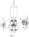
- the embodiment shown in Figure 1 in cross section in the form of a double seat leakage valve has a housing 7 with a seat 6 and has a closing body 5, which in the housing 7 between a closed position and a Open position is arranged slidably.
- the closing body 5 is as with double-seat leakage valves known, formed of two closing members, which are relatively can be moved to each other. Both closing members are made of two parts 5 ', 5 "and 5a', 5a" composed.
- To close the valve works the Locking body 5, as shown in the section B, with the seat 6 together.
- One in this position between the closing body 5 and the seat 6 remaining Gap is sealed by two multi-part seals 10.
- a different built valve can basically a single multi-part, of course Sealing 10 should be sufficient.
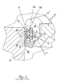
- FIG. 2 shows the detail A of Figure 1 for clarity in a Magnification
- the annular groove 4 is executed wedge-shaped undercut.
- the legs 3b of FIG Support ring 3 where they support the sealing ring 1, rounded convex executed and rejuvenated towards their free ends.
- the effect Supporting ring by this way, in a manner like a wedge on the sealing ring 1 and causes a particularly high contact pressure of the legs 1b of the Seal 1 to the side walls 4b of the annular groove. 4
- the sealing ring 1 has in that area in which it supports the support ring 3 is, in cross-section, a waist 11 with a constriction.
- the waist 11 can in Be preformed sealing ring 1; but it is also possible, they only by a from Support ring outgoing contact pressure to form when the sealing ring 1 with his two legs 1 b between the legs 3b of the support ring 3 and the side walls 4b of the groove 4 is clamped and by the occurring Pressure the waist 11 is shaped.
- the built-sealing ring 1 is in the groove 4 anyway under tension.
- the sealing ring 1 is due to the bottleneck in the waist 11 thus not only frictionally by pressing against the side walls 4b of the annular groove. 4 held by the support ring 3 in its position, but also positively in his Position fixed.
- Another advantage that the sealing ring 1 in the region of a bottleneck is supported by the support ring 3, is that thermally induced size changes, which are naturally proportional to the volume involved, in the area of the bottleneck least, so even with a cool down of the sealing ring 1 at most negligible contact pressure.
- the training of the waist 11 is accompanied by the formation of two in cross section wedge-shaped sections of the sealing ring 1, the thinnest point just the bottleneck the waist is 11.
- Increasing Pressure in the pending medium thus increases the sealing effect - a most welcome advantage of the invention, especially when used in the food industry, in the beverage industry and in the pharmaceutical industry, where it depends on the utmost purity and sterility.
- the ring 2 responding to deformation with a restoring force is between the two Legs 3b of the support ring 3 is arranged. These legs 3b form together to a certain extent a chamber with the sealing ring 1, whereby the dynamically stressed Area of the multi-part seal 10 from the clamping point of the sealing ring 1 is decoupled.
- the ring 2 is installed under prestress, so that it is subject to well-defined conditions.
- the ring 2 is in Surround its installation position of open spaces 12, which are dimensioned so that the ring 2 just the necessary volume is available to at a By closing the valve related deformation the desired elastic Show behavior. Due to the tight free spaces 12 and the bias of the ring 2 are the movements of the ring 2 when closing the Valve limited to the necessary level.
- the legs 1b of the sealing ring 1 thicken towards its free end.
- a free space 9 is provided, which material of the preferably made of a filled PTFE sealing ring 1 in the case of a thermal Expansion and absorbs during compression.
- FIG. 3 shows a multipart valve seal 10 of the valve shown in FIG in cross section.
- the support ring 3 is preferably made of steel or another metal made to exert or absorb the highest possible forces on the sealing ring 1 to be able to.
- the support ring 3 is made in four parts.
- FIG. 4 shows one along the section line C-C in FIG 3 executed longitudinal section.
- the support ring is 3 of four approximately equal sections 3 '(segments) together.
- the closing members of the closing body 5 are the closing members of the closing body 5 in their parts 5 'and 5 "and 5a' and 5a" decomposed.
- the joints between These parts 5 'and 5 "and 5a' and 5a” each extend in one of the annular grooves 4, so that the annular grooves 4 are easily accessible.
- this is first from the sealing ring 1, the deformation with a restoring force responsive ring 2 and the segments 3 'of the support ring. 3 composed.
- the composite multi-part seal 10 in the annular groove 4 are the parts 5 'and 5 "and 5a' and 5a" of the closing body 5, preferably by Screw together, put together, whereby the sealing ring 1 between the Side walls 4b of the annular groove 4 and the support ring 3 is fixed and pressed.
- take the ring 2 the segments 3 'of the support ring 3 and the sealing ring 1 in the annular groove 4 as well as relative to each other their final position one.
Landscapes
- Engineering & Computer Science (AREA)
- General Engineering & Computer Science (AREA)
- Mechanical Engineering (AREA)
- Lift Valve (AREA)
- Sealing Devices (AREA)
- Check Valves (AREA)
- Gasket Seals (AREA)
- Multiple-Way Valves (AREA)
Description
- Figur 1
- ein Ausführungsbeispiel eines erfindungsgemäßen Ventiles in Form eines Doppelsitz-Leckageventils mit Ausschnittsvergrößerungen im Bereich der mehrteiligen Dichtungen,
- Figur 2
- den in Figur 1 gezeigten Ausschnitt A eines Querschnittes des Ausführungsbeispieles im Bereich einer mehrteiligen Dichtung,
- Figur 3
- eine mehrteilige Ventildichtung im Querschnitt, und
- Figur 4
- eine mehrteilige Ventildichtung im Längsschnitt entlang der Schnittebene C-C der Figur 3.
Claims (24)
- Ventil, insbesondere Doppelsitz-Leckageventil, für die Lebensmittel-, Getränke- und die pharmazeutische Industrie,
mit einem Gehäuse (7), das einen Sitz (6) aufweist,
mit einem Schließkörper (5), der im Gehäuse (7) zwischen einer Schließstellung und einer Offenstellung verschiebbar angeordnet ist und zum Schließen des Ventils mit dem Sitz (6) zusammenarbeitet,
und mit einem zwischen dem Schließkörper (5) und dem Sitz (6) wirkenden Dichtring (1), welcher in einer Ringnut (4) angeordnet ist, wobei
der Dichtring (1) einen zur Ringnut (4) hin offenen U-oder C-förmigen Querschnitt mit zwei Schenkeln (1b) aufweist und von einem Stützring (3), der einen zum Dichtring (1) hin geöffneten U- oder C-förmigen Querschnitt mit zwei Schenkeln (3b) aufweist, gestützt wird und wobei zwischen dem Stützring (3) und dem Dichtring (1) ein auf Verformung mit einer Rückstellkraft antwortender Ring (2) angeordnet ist,
dadurch gekennzeichnet, dass der Dichtring (1) in der Ringnut (4) bereits dort, wo er die Seitenwand (4b) der Ringnut (4), von der Öffnung der Ringnut (4) aus gesehen, in der Offenstellung des Ventils erstmals berührt, und in einen daran anschließenden Bereich von dem Stützring (3) unterstützt wird. - Ventil nach Anspruch 1, dadurch gekennzeichnet, dass die Ringnut (4) im Schließkörper (5) angeordnet ist.
- Ventil nach Anspruch 1, dadurch gekennzeichnet, dass die Ringnut (4) im Sitz (6) angeordnet ist.
- Ventil nach Anspruch 1, 2 oder 3, dadurch gekennzeichnet, dass der Dichtring (1) in der Ringnut (4), von der Öffnung der Ringnut (4) aus gesehen, genau ab dort, wo er die Seitenwand (4b) der Ringnut (4) in der Offenstellung des Ventils erstmals berührt, von dem Stützring (3) unterstützt wird.
- Ventil nach einem der vorstehenden Ansprüche, dadurch gekennzeichnet, dass der Stützring (3) die Schenkel (1b) des Dichtringes (1) gegen die Seitenwände (4b) der Ringnut (4) drückt.
- Ventil nach einem der vorstehenden Ansprüche, dadurch gekennzeichnet, dass der Schließkörper (5) bzw. der Sitz (6) einen ersten und einen zweiten Teil (5', 5" sowie 5a' und 5a") aufweist, wobei die Fuge zwischen den beiden Teilen (5', 5" sowie 5a' und 5a") innerhalb der Ringnut (4) verläuft.
- Ventil nach einem der vorstehenden Ansprüche, dadurch gekennzeichnet, dass die Ringnut (4) hinterschnitten, insbesondere keilförmig hinterschnitten, ist.
- Ventil nach einem der vorstehenden Ansprüche, dadurch gekennzeichnet, dass die Schenkel (3b) des Stützringes (3) in einem an dem Dichtring (1) anliegenden Bereich konvex gerundet ausgeführt sind.
- Ventil nach Anspruch 8, dadurch gekennzeichnet, dass der Dichtring (1) in dem vom Stützring (3) unterstützten Bereich konkav ausgebildet ist.
- Ventil nach einem der vorstehenden Ansprüche, dadurch gekennzeichnet, dass der Dichtring (1) in dem vom Stützring (3) unterstützten Bereich im Querschnitt gesehen eine Taille (11) aufweist.
- Ventil nach Anspruch 10, dadurch gekennzeichnet, dass sich die Taille (11) unmittelbar an oder neben jener Stelle befindet, an welcher der Dichtring (1) die Seitenwand (46) der Ringnut (4) in der Offenstellung des Ventils erstmals berührt.
- Ventil nach einem der vorstehenden Ansprüche, dadurch gekennzeichnet, dass sich die Schenkel (1b) des Dichtringes (1) zu ihrem freien Ende hin verdicken.
- Ventil nach einem der vorstehenden Ansprüche, dadurch gekennzeichnet, dass sich die Schenkel (3b) des Stützringes (3) zu ihren freien Enden hin verjüngen.
- Ventil nach einem der vorstehenden Ansprüche, dadurch gekennzeichnet, dass am Grund der Ringnut (4) zwischen dem Stützring (3) und den Schenkeln (1b) des Dichtringes (1) ein Freiraum (9) vorgesehen ist.
- Ventil nach einem der vorstehenden Ansprüche, dadurch gekennzeichnet, dass sich der Stützring (3) unmittelbar auf dem Grund der Ringnut (4) abstützt.
- Ventil nach einem der vorstehenden Ansprüche, dadurch gekennzeichnet, dass der Dichtring (1) aus einem PTFE, insbesondere aus einem gefüllten PTFE gefertigt ist.
- Ventil nach einem der vorstehenden Ansprüche, dadurch gekennzeichnet, dass sich der Dichtring (1) über die Ringnut (4) vorwölbt.
- Ventil nach einem der vorstehenden Ansprüche, dadurch gekennzeichnet, dass der auf Verformung mit einer Rückstellkraft antwortende Ring (2) aus einem elastischeren Material als der Dichtring (1) besteht.
- Ventil nach einem der vorstehenden Ansprüche, dadurch gekennzeichnet, dass der auf Verformung mit einer Rückstellkraft antwortende Ring (2) aus einem elastomeren Material ist.
- Ventil nach einem der vorstehenden Ansprüche, dadurch gekennzeichnet, dass der auf Verformung mit einer Rückstellkraft antwortende Ring (2) ein O-Ring ist.
- Ventil nach einem der Ansprüche 1 bis 17, dadurch gekennzeichnet, dass der auf Verformung mit einer Rückstellkraft antwortende Ring (2) als metallisches Federelement, insbesondere als Wendelfeder, ausgeführt ist.
- Ventil nach einem der vorstehenden Ansprüche, dadurch gekennzeichnet, dass der Stützring (3) aus mehreren Segmenten (3'), insbesondere aus vier Segmenten (3') zusammengesetzt ist.
- Ventil nach Anspruch 21, dadurch gekennzeichnet, dass die Stoßflächen (3") zwischen benachbarten Segmenten (3') eine von der radialen Orientierung abweichende Orientierung haben.
- Ventil nach einem der vorstehenden Ansprüche, dadurch gekennzeichnet, dass der Stützring (3) aus Metall ist.
Applications Claiming Priority (2)
| Application Number | Priority Date | Filing Date | Title |
|---|---|---|---|
| DE10147455A DE10147455C5 (de) | 2001-09-20 | 2001-09-20 | Ventil mit mehrteiliger Ventildichtung |
| DE10147455 | 2001-09-20 |
Publications (4)
| Publication Number | Publication Date |
|---|---|
| EP1296087A2 EP1296087A2 (de) | 2003-03-26 |
| EP1296087A3 EP1296087A3 (de) | 2004-01-02 |
| EP1296087B1 true EP1296087B1 (de) | 2005-02-16 |
| EP1296087B2 EP1296087B2 (de) | 2011-07-27 |
Family
ID=7700348
Family Applications (1)
| Application Number | Title | Priority Date | Filing Date |
|---|---|---|---|
| EP02021019A Expired - Lifetime EP1296087B2 (de) | 2001-09-20 | 2002-09-20 | Ventil mit mehrteiliger Ventildichtung |
Country Status (4)
| Country | Link |
|---|---|
| EP (1) | EP1296087B2 (de) |
| AT (1) | ATE289392T1 (de) |
| DE (2) | DE10147455C5 (de) |
| DK (1) | DK1296087T3 (de) |
Cited By (2)
| Publication number | Priority date | Publication date | Assignee | Title |
|---|---|---|---|---|
| DE102006025653B4 (de) * | 2006-03-14 | 2009-02-05 | Kieselmann Gmbh | Aseptisches Doppelsitzventil |
| DE202012000850U1 (de) | 2011-03-11 | 2012-03-05 | Gea Tuchenhagen Gmbh | Antimikrobielle Materialien und Beschichtungen in Prozesskomponenten |
Families Citing this family (8)
| Publication number | Priority date | Publication date | Assignee | Title |
|---|---|---|---|---|
| US8327881B2 (en) | 2008-09-19 | 2012-12-11 | Spx Corporation | Double seat valve apparatus |
| DE102010030298A1 (de) * | 2010-06-21 | 2011-12-22 | Krones Aktiengesellschaft | Mehrteiliger Ventilteller |
| DE102010030300A1 (de) | 2010-06-21 | 2011-12-22 | Krones Aktiengesellschaft | Doppelsitzventil und Abdichtung eines Doppelsitzventils |
| DE102014114977A1 (de) | 2014-10-15 | 2016-04-21 | Kieselmann Gmbh | Ringdichtung und Ventilteller mit einer solchen Ringdichtung |
| DE102014223678A1 (de) * | 2014-11-20 | 2016-05-25 | Robert Bosch Gmbh | Gasventil und Verfahren zur Herstellung eines Dichtelements |
| CN106032863A (zh) * | 2015-03-19 | 2016-10-19 | 山东钢铁股份有限公司 | 一种法兰以及使用该法兰的动态平衡阀 |
| CN106567934B (zh) * | 2015-10-08 | 2020-11-06 | 浙江盾安机械有限公司 | 一种截止阀 |
| EP3371496B1 (de) * | 2015-11-04 | 2020-12-30 | Fisher Controls International Llc | Anordnung zum hochfahren von prüfströmungsreglervorrichtungen bei verschiedenen druckwerten und temperaturen |
Family Cites Families (10)
| Publication number | Priority date | Publication date | Assignee | Title |
|---|---|---|---|---|
| US2911184A (en) * | 1957-01-14 | 1959-11-03 | Telecomputing Corp | Pressure loaded seal |
| DE1425441A1 (de) * | 1963-05-17 | 1969-11-27 | Bosch Gmbh Robert | Elastische Abdichtung |
| DE2440698A1 (de) * | 1973-08-27 | 1975-03-13 | Juha Antti Elia Nelimarkka | Dichtung fuer ein klappenventil |
| FR2255522B1 (de) * | 1973-12-19 | 1982-11-12 | Amri | |
| DE3638703A1 (de) | 1986-11-13 | 1988-05-26 | Merkel Martin Gmbh Co Kg | Flachdichtungsmaterial aus fluorkunststoff |
| DE8813258U1 (de) * | 1988-10-21 | 1989-04-20 | Leonhard Schleicher Südmo-Armaturenfabrik GmbH, 7081 Riesbürg | Absperrventil mit Leckagesicherung |
| DE4118874C2 (de) * | 1991-06-07 | 1995-02-16 | Tuchenhagen Otto Gmbh | Verfahren zur Reinigung eines leckagefrei schaltenden Doppelsitzventils und Ventilvorrichtung zum Durchführen des Verfahrens |
| US5472216A (en) * | 1994-09-30 | 1995-12-05 | Parker-Hannifin Corporation | Seal ring for valve stem |
| DE29818551U1 (de) * | 1998-04-20 | 1999-02-18 | Kieselmann GmbH, 75438 Knittlingen | Ventil, insbesondere Doppelsitz-Leckageventil |
| DE20019779U1 (de) * | 2000-11-15 | 2001-04-19 | Kieselmann GmbH, 75438 Knittlingen | Ventil, insbesondere Doppelsitz-Leckageventil |
-
2001
- 2001-09-20 DE DE10147455A patent/DE10147455C5/de not_active Expired - Fee Related
-
2002
- 2002-09-20 AT AT02021019T patent/ATE289392T1/de not_active IP Right Cessation
- 2002-09-20 DK DK02021019T patent/DK1296087T3/da active
- 2002-09-20 DE DE50202269T patent/DE50202269D1/de not_active Expired - Lifetime
- 2002-09-20 EP EP02021019A patent/EP1296087B2/de not_active Expired - Lifetime
Cited By (4)
| Publication number | Priority date | Publication date | Assignee | Title |
|---|---|---|---|---|
| DE102006025653B4 (de) * | 2006-03-14 | 2009-02-05 | Kieselmann Gmbh | Aseptisches Doppelsitzventil |
| DE102006025653C5 (de) * | 2006-03-14 | 2010-10-14 | Kieselmann Gmbh | Aseptisches Doppelsitzventil |
| DE202012000850U1 (de) | 2011-03-11 | 2012-03-05 | Gea Tuchenhagen Gmbh | Antimikrobielle Materialien und Beschichtungen in Prozesskomponenten |
| EP2497979A1 (de) | 2011-03-11 | 2012-09-12 | GEA Tuchenhagen GmbH | Verwendung antimikrobieller Materialien und Beschichtungen in Prozesskomponenten |
Also Published As
| Publication number | Publication date |
|---|---|
| EP1296087A2 (de) | 2003-03-26 |
| DE10147455C5 (de) | 2007-02-15 |
| ATE289392T1 (de) | 2005-03-15 |
| EP1296087B2 (de) | 2011-07-27 |
| DE50202269D1 (de) | 2005-03-24 |
| DE10147455C1 (de) | 2003-04-17 |
| EP1296087A3 (de) | 2004-01-02 |
| DK1296087T3 (da) | 2005-06-13 |
Similar Documents
| Publication | Publication Date | Title |
|---|---|---|
| DE60121635T2 (de) | Verbesserter Dichtring | |
| EP2397727B1 (de) | Mehrteiliger Ventilteller | |
| DE2627652A1 (de) | Ventil | |
| EP1296087B2 (de) | Ventil mit mehrteiliger Ventildichtung | |
| EP2397731B1 (de) | Doppelsitzventil und Abdichtung eines Doppelsitzventils | |
| EP0205170A2 (de) | Druckdichtes Kupplungsstück für ein Rohr | |
| EP1509308B1 (de) | Vorrichtung zum filtern von unter einem hohen druck geförderten fluiden | |
| DE20205467U1 (de) | Ventil, insbesondere Doppelsitz-Leckageventil | |
| EP3824207B1 (de) | Hubventil und dichtung | |
| DE2816930A1 (de) | Stopfbuchsdichtung | |
| DE1600758A1 (de) | Dichtung | |
| DE60315785T2 (de) | Pumpe | |
| DE19800827C1 (de) | Dichtung | |
| DE102020112696B4 (de) | Ventil sowie Membranpumpe mit Ein- und Auslassventilen | |
| DE102004018054B4 (de) | Dichtungsbalg | |
| EP0412997A1 (de) | Dichtungsanordnung. | |
| DE20115857U1 (de) | Ventil mit mehrteiliger Ventildichtung | |
| DE3606011A1 (de) | Extrusionssteifer dichtring | |
| DE29501054U1 (de) | Lösbare Rohrerbindung, vorzugsweise für sterile und partikelfreie Leitungssysteme | |
| DE29818551U1 (de) | Ventil, insbesondere Doppelsitz-Leckageventil | |
| EP0260482B1 (de) | Absperrhahn mit zylindrischem oder konischem Küken | |
| DE2906855A1 (de) | Biegsame dichtung und befestigungsvorrichtung hierfuer | |
| EP1231996A2 (de) | Pressmembran aus einem gummielastischen material | |
| EP1039182B1 (de) | Dichtvorrichtung und Sitzventil | |
| DE10057718B4 (de) | Ventil, insbesondere Doppelsitz-Leckageventil |
Legal Events
| Date | Code | Title | Description |
|---|---|---|---|
| PUAI | Public reference made under article 153(3) epc to a published international application that has entered the european phase |
Free format text: ORIGINAL CODE: 0009012 |
|
| AK | Designated contracting states |
Kind code of ref document: A2 Designated state(s): AT BE BG CH CY CZ DE DK EE ES FI FR GB GR IE IT LI LU MC NL PT SE SK TR |
|
| AX | Request for extension of the european patent |
Extension state: AL LT LV MK RO SI |
|
| PUAL | Search report despatched |
Free format text: ORIGINAL CODE: 0009013 |
|
| AK | Designated contracting states |
Kind code of ref document: A3 Designated state(s): AT BE BG CH CY CZ DE DK EE ES FI FR GB GR IE IT LI LU MC NL PT SE SK TR |
|
| AX | Request for extension of the european patent |
Extension state: AL LT LV MK RO SI |
|
| GRAP | Despatch of communication of intention to grant a patent |
Free format text: ORIGINAL CODE: EPIDOSNIGR1 |
|
| 17P | Request for examination filed |
Effective date: 20040623 |
|
| AKX | Designation fees paid |
Designated state(s): AT BE BG CH CY CZ DE DK EE ES FI FR GB GR IE IT LI LU MC NL PT SE SK TR |
|
| GRAS | Grant fee paid |
Free format text: ORIGINAL CODE: EPIDOSNIGR3 |
|
| GRAA | (expected) grant |
Free format text: ORIGINAL CODE: 0009210 |
|
| AK | Designated contracting states |
Kind code of ref document: B1 Designated state(s): AT BE BG CH CY CZ DE DK EE ES FI FR GB GR IE IT LI LU MC NL PT SE SK TR |
|
| PG25 | Lapsed in a contracting state [announced via postgrant information from national office to epo] |
Ref country code: IE Free format text: LAPSE BECAUSE OF FAILURE TO SUBMIT A TRANSLATION OF THE DESCRIPTION OR TO PAY THE FEE WITHIN THE PRESCRIBED TIME-LIMIT Effective date: 20050216 Ref country code: SK Free format text: LAPSE BECAUSE OF FAILURE TO SUBMIT A TRANSLATION OF THE DESCRIPTION OR TO PAY THE FEE WITHIN THE PRESCRIBED TIME-LIMIT Effective date: 20050216 Ref country code: GB Free format text: LAPSE BECAUSE OF FAILURE TO SUBMIT A TRANSLATION OF THE DESCRIPTION OR TO PAY THE FEE WITHIN THE PRESCRIBED TIME-LIMIT Effective date: 20050216 Ref country code: FI Free format text: LAPSE BECAUSE OF FAILURE TO SUBMIT A TRANSLATION OF THE DESCRIPTION OR TO PAY THE FEE WITHIN THE PRESCRIBED TIME-LIMIT Effective date: 20050216 Ref country code: CZ Free format text: LAPSE BECAUSE OF FAILURE TO SUBMIT A TRANSLATION OF THE DESCRIPTION OR TO PAY THE FEE WITHIN THE PRESCRIBED TIME-LIMIT Effective date: 20050216 Ref country code: EE Free format text: LAPSE BECAUSE OF FAILURE TO SUBMIT A TRANSLATION OF THE DESCRIPTION OR TO PAY THE FEE WITHIN THE PRESCRIBED TIME-LIMIT Effective date: 20050216 Ref country code: BG Free format text: LAPSE BECAUSE OF FAILURE TO SUBMIT A TRANSLATION OF THE DESCRIPTION OR TO PAY THE FEE WITHIN THE PRESCRIBED TIME-LIMIT Effective date: 20050216 Ref country code: NL Free format text: LAPSE BECAUSE OF FAILURE TO SUBMIT A TRANSLATION OF THE DESCRIPTION OR TO PAY THE FEE WITHIN THE PRESCRIBED TIME-LIMIT Effective date: 20050216 Ref country code: TR Free format text: LAPSE BECAUSE OF FAILURE TO SUBMIT A TRANSLATION OF THE DESCRIPTION OR TO PAY THE FEE WITHIN THE PRESCRIBED TIME-LIMIT Effective date: 20050216 |
|
| REG | Reference to a national code |
Ref country code: GB Ref legal event code: FG4D Free format text: NOT ENGLISH |
|
| REG | Reference to a national code |
Ref country code: CH Ref legal event code: EP |
|
| REG | Reference to a national code |
Ref country code: IE Ref legal event code: FG4D Free format text: GERMAN |
|
| REF | Corresponds to: |
Ref document number: 50202269 Country of ref document: DE Date of ref document: 20050324 Kind code of ref document: P |
|
| PG25 | Lapsed in a contracting state [announced via postgrant information from national office to epo] |
Ref country code: GR Free format text: LAPSE BECAUSE OF FAILURE TO SUBMIT A TRANSLATION OF THE DESCRIPTION OR TO PAY THE FEE WITHIN THE PRESCRIBED TIME-LIMIT Effective date: 20050516 Ref country code: SE Free format text: LAPSE BECAUSE OF FAILURE TO SUBMIT A TRANSLATION OF THE DESCRIPTION OR TO PAY THE FEE WITHIN THE PRESCRIBED TIME-LIMIT Effective date: 20050516 |
|
| PG25 | Lapsed in a contracting state [announced via postgrant information from national office to epo] |
Ref country code: ES Free format text: LAPSE BECAUSE OF FAILURE TO SUBMIT A TRANSLATION OF THE DESCRIPTION OR TO PAY THE FEE WITHIN THE PRESCRIBED TIME-LIMIT Effective date: 20050527 |
|
| REG | Reference to a national code |
Ref country code: DK Ref legal event code: T3 |
|
| REG | Reference to a national code |
Ref country code: CH Ref legal event code: NV Representative=s name: WILLIAM BLANC & CIE CONSEILS EN PROPRIETE INDUSTRI |
|
| PG25 | Lapsed in a contracting state [announced via postgrant information from national office to epo] |
Ref country code: PT Free format text: LAPSE BECAUSE OF FAILURE TO SUBMIT A TRANSLATION OF THE DESCRIPTION OR TO PAY THE FEE WITHIN THE PRESCRIBED TIME-LIMIT Effective date: 20050725 |
|
| NLV1 | Nl: lapsed or annulled due to failure to fulfill the requirements of art. 29p and 29m of the patents act | ||
| GBV | Gb: ep patent (uk) treated as always having been void in accordance with gb section 77(7)/1977 [no translation filed] |
Effective date: 20050216 |
|
| PG25 | Lapsed in a contracting state [announced via postgrant information from national office to epo] |
Ref country code: CY Free format text: LAPSE BECAUSE OF FAILURE TO SUBMIT A TRANSLATION OF THE DESCRIPTION OR TO PAY THE FEE WITHIN THE PRESCRIBED TIME-LIMIT Effective date: 20050920 |
|
| REG | Reference to a national code |
Ref country code: IE Ref legal event code: FD4D |
|
| PG25 | Lapsed in a contracting state [announced via postgrant information from national office to epo] |
Ref country code: MC Free format text: LAPSE BECAUSE OF NON-PAYMENT OF DUE FEES Effective date: 20050930 Ref country code: LU Free format text: LAPSE BECAUSE OF NON-PAYMENT OF DUE FEES Effective date: 20050930 |
|
| PLBI | Opposition filed |
Free format text: ORIGINAL CODE: 0009260 |
|
| PLAX | Notice of opposition and request to file observation + time limit sent |
Free format text: ORIGINAL CODE: EPIDOSNOBS2 |
|
| 26 | Opposition filed |
Opponent name: TUCHENHAGEN GMBH Effective date: 20051104 |
|
| ET | Fr: translation filed | ||
| PGFP | Annual fee paid to national office [announced via postgrant information from national office to epo] |
Ref country code: BE Payment date: 20060313 Year of fee payment: 4 |
|
| PLAF | Information modified related to communication of a notice of opposition and request to file observations + time limit |
Free format text: ORIGINAL CODE: EPIDOSCOBS2 |
|
| PLBB | Reply of patent proprietor to notice(s) of opposition received |
Free format text: ORIGINAL CODE: EPIDOSNOBS3 |
|
| PG25 | Lapsed in a contracting state [announced via postgrant information from national office to epo] |
Ref country code: BE Free format text: LAPSE BECAUSE OF NON-PAYMENT OF DUE FEES Effective date: 20060930 |
|
| BERE | Be: lapsed |
Owner name: KIESELMANN G.M.B.H. Effective date: 20060930 |
|
| APBP | Date of receipt of notice of appeal recorded |
Free format text: ORIGINAL CODE: EPIDOSNNOA2O |
|
| APAH | Appeal reference modified |
Free format text: ORIGINAL CODE: EPIDOSCREFNO |
|
| APBQ | Date of receipt of statement of grounds of appeal recorded |
Free format text: ORIGINAL CODE: EPIDOSNNOA3O |
|
| PLAB | Opposition data, opponent's data or that of the opponent's representative modified |
Free format text: ORIGINAL CODE: 0009299OPPO |
|
| R26 | Opposition filed (corrected) |
Opponent name: GEA TUCHENHAGEN GMBH Effective date: 20051104 |
|
| PGFP | Annual fee paid to national office [announced via postgrant information from national office to epo] |
Ref country code: DK Payment date: 20090921 Year of fee payment: 8 |
|
| PGFP | Annual fee paid to national office [announced via postgrant information from national office to epo] |
Ref country code: AT Payment date: 20090921 Year of fee payment: 8 Ref country code: CH Payment date: 20090923 Year of fee payment: 8 |
|
| PGFP | Annual fee paid to national office [announced via postgrant information from national office to epo] |
Ref country code: IT Payment date: 20090925 Year of fee payment: 8 |
|
| REG | Reference to a national code |
Ref country code: CH Ref legal event code: PFA Owner name: KIESELMANN GMBH Free format text: KIESELMANN GMBH#PAUL-KIESELMANN-STRASSE 4-6#75438 KNITTLINGEN (DE) -TRANSFER TO- KIESELMANN GMBH#PAUL-KIESELMANN-STRASSE 4-6#75438 KNITTLINGEN (DE) |
|
| APBU | Appeal procedure closed |
Free format text: ORIGINAL CODE: EPIDOSNNOA9O |
|
| REG | Reference to a national code |
Ref country code: CH Ref legal event code: PL |
|
| REG | Reference to a national code |
Ref country code: DK Ref legal event code: EBP |
|
| PG25 | Lapsed in a contracting state [announced via postgrant information from national office to epo] |
Ref country code: IT Free format text: LAPSE BECAUSE OF NON-PAYMENT OF DUE FEES Effective date: 20100920 |
|
| PUAH | Patent maintained in amended form |
Free format text: ORIGINAL CODE: 0009272 |
|
| REG | Reference to a national code |
Ref country code: FR Ref legal event code: ST Effective date: 20110531 |
|
| STAA | Information on the status of an ep patent application or granted ep patent |
Free format text: STATUS: PATENT MAINTAINED AS AMENDED |
|
| 27A | Patent maintained in amended form |
Effective date: 20110727 |
|
| AK | Designated contracting states |
Kind code of ref document: B2 Designated state(s): AT BE BG CH CY CZ DE DK EE ES FI FR GB GR IE IT LI LU MC NL PT SE SK TR |
|
| REG | Reference to a national code |
Ref country code: DE Ref legal event code: R102 Ref document number: 50202269 Country of ref document: DE |
|
| PG25 | Lapsed in a contracting state [announced via postgrant information from national office to epo] |
Ref country code: FR Free format text: LAPSE BECAUSE OF NON-PAYMENT OF DUE FEES Effective date: 20100930 Ref country code: LI Free format text: LAPSE BECAUSE OF NON-PAYMENT OF DUE FEES Effective date: 20100930 Ref country code: CH Free format text: LAPSE BECAUSE OF NON-PAYMENT OF DUE FEES Effective date: 20100930 |
|
| PG25 | Lapsed in a contracting state [announced via postgrant information from national office to epo] |
Ref country code: AT Free format text: LAPSE BECAUSE OF NON-PAYMENT OF DUE FEES Effective date: 20100920 |
|
| REG | Reference to a national code |
Ref country code: DE Ref legal event code: R102 Ref document number: 50202269 Country of ref document: DE Effective date: 20110727 |
|
| PGFP | Annual fee paid to national office [announced via postgrant information from national office to epo] |
Ref country code: FR Payment date: 20091005 Year of fee payment: 8 |
|
| PG25 | Lapsed in a contracting state [announced via postgrant information from national office to epo] |
Ref country code: DK Free format text: LAPSE BECAUSE OF NON-PAYMENT OF DUE FEES Effective date: 20100930 |
|
| PGFP | Annual fee paid to national office [announced via postgrant information from national office to epo] |
Ref country code: DE Payment date: 20210716 Year of fee payment: 20 |
|
| REG | Reference to a national code |
Ref country code: DE Ref legal event code: R071 Ref document number: 50202269 Country of ref document: DE |