EP1296134B1 - Dispositif d'échantillonnage et son utilisation pour contrôler l'introduction d'échantillons dans les techniques de séparation par microcolonnes - Google Patents
Dispositif d'échantillonnage et son utilisation pour contrôler l'introduction d'échantillons dans les techniques de séparation par microcolonnes Download PDFInfo
- Publication number
- EP1296134B1 EP1296134B1 EP02028452.7A EP02028452A EP1296134B1 EP 1296134 B1 EP1296134 B1 EP 1296134B1 EP 02028452 A EP02028452 A EP 02028452A EP 1296134 B1 EP1296134 B1 EP 1296134B1
- Authority
- EP
- European Patent Office
- Prior art keywords
- sample
- channel
- electrolyte
- drain
- supply
- Prior art date
- Legal status (The legal status is an assumption and is not a legal conclusion. Google has not performed a legal analysis and makes no representation as to the accuracy of the status listed.)
- Expired - Lifetime
Links
- 238000005070 sampling Methods 0.000 title claims description 36
- 238000000926 separation method Methods 0.000 title claims description 16
- 239000003792 electrolyte Substances 0.000 claims description 49
- 230000005684 electric field Effects 0.000 claims description 19
- 239000002699 waste material Substances 0.000 claims description 13
- 239000000523 sample Substances 0.000 description 103
- 238000002347 injection Methods 0.000 description 11
- 239000007924 injection Substances 0.000 description 11
- 238000000034 method Methods 0.000 description 11
- 239000000203 mixture Substances 0.000 description 11
- 238000005251 capillar electrophoresis Methods 0.000 description 10
- 230000037230 mobility Effects 0.000 description 10
- 238000004458 analytical method Methods 0.000 description 6
- 238000001514 detection method Methods 0.000 description 6
- 239000012530 fluid Substances 0.000 description 6
- 238000009792 diffusion process Methods 0.000 description 5
- 238000004519 manufacturing process Methods 0.000 description 5
- 239000011521 glass Substances 0.000 description 4
- 230000005012 migration Effects 0.000 description 4
- 238000013508 migration Methods 0.000 description 4
- 239000004065 semiconductor Substances 0.000 description 4
- 239000000126 substance Substances 0.000 description 4
- 238000001962 electrophoresis Methods 0.000 description 3
- 239000000758 substrate Substances 0.000 description 3
- XUIMIQQOPSSXEZ-UHFFFAOYSA-N Silicon Chemical compound [Si] XUIMIQQOPSSXEZ-UHFFFAOYSA-N 0.000 description 2
- 238000007598 dipping method Methods 0.000 description 2
- 230000000694 effects Effects 0.000 description 2
- 239000008151 electrolyte solution Substances 0.000 description 2
- 229940021013 electrolyte solution Drugs 0.000 description 2
- 238000005370 electroosmosis Methods 0.000 description 2
- 230000006872 improvement Effects 0.000 description 2
- 239000012469 less concentrated sample Substances 0.000 description 2
- 239000000463 material Substances 0.000 description 2
- 229920000642 polymer Polymers 0.000 description 2
- 229910052710 silicon Inorganic materials 0.000 description 2
- 239000010703 silicon Substances 0.000 description 2
- 239000002904 solvent Substances 0.000 description 2
- 238000010521 absorption reaction Methods 0.000 description 1
- 239000003125 aqueous solvent Substances 0.000 description 1
- 230000008901 benefit Effects 0.000 description 1
- 238000004587 chromatography analysis Methods 0.000 description 1
- 230000001419 dependent effect Effects 0.000 description 1
- 238000011156 evaluation Methods 0.000 description 1
- 238000004401 flow injection analysis Methods 0.000 description 1
- 238000001917 fluorescence detection Methods 0.000 description 1
- 230000005484 gravity Effects 0.000 description 1
- 230000012447 hatching Effects 0.000 description 1
- 238000005259 measurement Methods 0.000 description 1
- 238000004452 microanalysis Methods 0.000 description 1
- 230000003287 optical effect Effects 0.000 description 1
- 239000002861 polymer material Substances 0.000 description 1
- 238000005086 pumping Methods 0.000 description 1
- 230000009467 reduction Effects 0.000 description 1
Images
Classifications
-
- C—CHEMISTRY; METALLURGY
- C07—ORGANIC CHEMISTRY
- C07K—PEPTIDES
- C07K1/00—General methods for the preparation of peptides, i.e. processes for the organic chemical preparation of peptides or proteins of any length
- C07K1/14—Extraction; Separation; Purification
- C07K1/24—Extraction; Separation; Purification by electrochemical means
- C07K1/26—Electrophoresis
-
- G—PHYSICS
- G01—MEASURING; TESTING
- G01N—INVESTIGATING OR ANALYSING MATERIALS BY DETERMINING THEIR CHEMICAL OR PHYSICAL PROPERTIES
- G01N27/00—Investigating or analysing materials by the use of electric, electrochemical, or magnetic means
- G01N27/26—Investigating or analysing materials by the use of electric, electrochemical, or magnetic means by investigating electrochemical variables; by using electrolysis or electrophoresis
- G01N27/416—Systems
- G01N27/447—Systems using electrophoresis
- G01N27/44704—Details; Accessories
- G01N27/44743—Introducing samples
-
- G—PHYSICS
- G01—MEASURING; TESTING
- G01N—INVESTIGATING OR ANALYSING MATERIALS BY DETERMINING THEIR CHEMICAL OR PHYSICAL PROPERTIES
- G01N27/00—Investigating or analysing materials by the use of electric, electrochemical, or magnetic means
- G01N27/26—Investigating or analysing materials by the use of electric, electrochemical, or magnetic means by investigating electrochemical variables; by using electrolysis or electrophoresis
- G01N27/416—Systems
- G01N27/447—Systems using electrophoresis
- G01N27/44756—Apparatus specially adapted therefor
- G01N27/44791—Microapparatus
Definitions
- the present invention concerns a sampling device according to patent claim 1 and its use for controlling sample introduction in microcolumn separation techniques.
- Microcolumn separation techniques in particular capillary electrophoresis has become a very interesting separation technique which is used as part of a sensor or a chemical analysis system.
- One major reason for this is the great efficiency of the method as a separation technique.
- the sampling methods usually applied in capillary electrophoresis are:
- sample valves are the most suitable sampling method for capillary electrophoresis
- a valveless device for the injection of a sample comprises a cast capillary block which is connected between an electrode compartment and a sampling device.
- electrolyte solutions contact electrodes.
- the capillary tube contains measuring electrodes which are connected with an evaluation electronics.
- the sampling device consists of a broadened part of the capillary tube connected with two feeders which extend perpendicular to the capillary tube. The arrangement of the two feeders off-set from each other along the longitudinal extension of the capillary-tube is such, that the sampling device has the shape of a capillary double T structure.
- the sample is introduced into the sampling device via a syringe.
- the injection volume is defined geometrically by the distance which the two feeders are spaced apart along the capillary tube.
- the transport of the electrolyte solution and the sample in the capillary tube is accomplished by electric fields that are applied between the respective electrodes along the capillary tube.
- the sample volume shall be geometrically defined.
- the composition of the sample which is injected shall not differ from the original composition of the sample in the reservoir.
- the uncontrolled introduction of sample fluid into the capillary tube shall be reduced considerably. If the unwanted leakage of sample fluid into the capillary tube cannot be totally avoided, provisions shall be made that at least it only occurs in a predictable and controllable manner.
- the method and the sampling device according to the invention shall also allow an easy realization of miniaturized analysis concepts, such as the ones described, for example, in Sensors and Actuators B, 10 (1993) 107-116 .
- miniaturized analysis concepts such as the ones described, for example, in Sensors and Actuators B, 10 (1993) 107-116 .
- a similar concept is described, for example, in Analytical Chemistry , Vol. 64, No. 17, September 1, 1992,1926-1932 .
- the described miniaturized chemical analysis system on the basis of capillary electrophoresis comprises a complex manifold of capillary channels, which are micromachined in a planar glass substrate. The transport of the solvent and the sample occurs due to electro-kinetic effects (electro-osmosis and/or electrophoresis).
- the objects of the invention are met by a device for controlling sample introduction in capillary electrophoresis (CE) according to patent claim 1.
- the sampling device can be used for controlling sample introduction in microcolumn separation techniques, especially in capillary electrophoresis (CE), wherein an electrolyte buffer and a more or less concentrated sample are transported through a system of capillary channels.
- the sample is injected as a sample plug into a sampling device which comprises at least a channel for the sample.
- the channel for the electrolyte buffer and the supply and drain channels for the sample intersect each other.
- the supply channel and the drain channel for the sample each discharge into the channel at respective supply and drain ports.
- the distance between the supply port and the drain port geometrically define a sample volume.
- the supply and the drain channels each are inclined to the electrolyte channel.
- the injection of the sample plug into the electrolyte channel is accomplished electro-kinetically by applying an electric field across the supply and drain channels for a time at least long enough that the sample component having the lowest electrophoretic mobility is contained within the geometrically defined volume. By this measure the composition of the injected sample plug will reflect the actual sample composition.
- the electrolyte buffer is allowed to advance into the supply channel and into the drain channel at the respective supply and drain ports for a time period, which amounts to at least the migration time of a slowest component within the sample plug from the supply port to the detector.
- the sample is pushed back into the respective supply and drain channels and substantially prevented from uncontrollably diffusing into the electrolyte buffer which is transported past the supply and drain ports.
- the method allows to control the sample composition within the electrolyte buffer.
- the sampling device comprises an electrolyte channel, and a supply channel and a drain channel for the sample, which discharge into the electrolyte channel at respective supply and drain ports.
- the ports are arranged with respect to each other such, that a sample volume is geometrically defined.
- the supply and drain channels each are inclined to the electrolyte channel. Means are provided for electro-kinetically injecting a sample into the sample volume.
- the resistance to flow of the source and drain channels with respect to the electrolyte buffer is at least about 5% lower than the respective resistance to flow of the electrolyte channel.
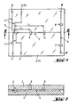
- FIG. 1 and 2 an exemplary embodiment of a microcolumn separation device, more particularly of an electrophoretic separation device, is depicted. It comprises a base part 1 and a lid part 2.
- the base part 1 can be made of glass, monocrystalin silicon or other materials known from semiconductor manufacture, or of a suitable polymer material.
- the lid part 2 is preferably made of glass.
- the base part 1 comprises a channel system 4 which is etched, micromachined or otherwise established in its surface. Preferably techniques known from semiconductor manufacture are applied for creating the channel system in the surface of the base part 1.
- the lid part is provided with through holes R, S, D, W, which communicate with the channel system 4 and are adapted to accomodate and hold the ends of capillary tubes.
- the lid part 2 is also provided with various ports for light waveguides, which are part of an optical detection system, such as, for example, a fluorescence detection system, or an absorption detection system, or a system for the detection of changes of the refractive index of a sample flowing through the channel system.
- the ports are distributed along the channel system 4 after a sampling device 3, where a sample is introduced into an electrolyte buffer, thus allowing measurements at different locations along the channel system.
- the transport of the electrolyte buffer and of the more or less concentrated sample is accomplished by means of electric fields, which are created by switching electric potentials between electrodes of a respective reservoir R and waste receptacles W for the electrolyte buffer and between electrodes associated with respective source S and drain receptacles D for the sample.
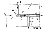
- FIG 3 the encircled sampling device 3 of Figure 1 is shown in an enlarged scale. It is part of the flow injection analysis system of Figure 1 , which is based on electro-kinetic principles and allows an electrophoretic analysis of a sample.
- the sampling device 3 is an integrated part of the capillary channel system 4 and is thus connected with the reservoir R and the waste receptacle W behind the detectors 5-8, for the electrolyte buffer, and with the source receptacle S and the drain receptacle D for the sample which is to be analyzed.
- the reservoir R and the receptacles W, S, D are not drawn, but they are only symbolized by arrows, which at the same time indicate the direction of fluid flow in the channel system 4.
- a first exemplary embodiment of the sampling device comprises a capillary channel piece 22, which on one end is connected to a capillary channel communicating with the reservoir R for the electrolyte buffer and in longitudinal direction on the other end with a capillary channel where the electrophoretic separation of the sample takes place, and which leads to the detector(s) and in further consequence to the waste receptacle(s) W.
- the sampling device further comprises a supply channel 23, which communicates with a source receptacle S for the sample, and a drain channel 24 which leads to a drain receptacle D.
- the source channel 23 and the drain channel 24 are inclined to the longitudinal extension of the channel piece 2, they are arranged about perpendicular such, that together with the channel piece 22 they form a double T structure, as shown in the drawing.
- the source channel S and the drain channel D each discharge into the channel piece 22 at respective supply and drain ports 25, 26.
- the supply port 25 and the drain port 26 are spaced apart from each other longitudinally at the channel piece 22 such, that a sample volume 27 is geometrically defined as will be explained in more detail hereinafter.
- the distance which they are spaced apart from each other typically amounts to from about 3 ⁇ m to about 3 cm, most preferably to about 3 mm.
- the transport of the fluids i.e. the electrolyte buffer and the sample
- electric fields which are a result of different electric potentials at the reservoir R and the waste receptacle W for the electrolyte buffer, and the respective source receptacle S and the drain receptacle D for the sample.
- the electrolyte buffer is electro-kinetically transported from the reservoir R through the capillary channel system to the waste receptacle W.
- the source receptacle In order to introduce the sample into the channel piece 22, for example, the source receptacle.
- the sample-filled part 27 of the channel piece of the sampling device 3 defines the volume of the electro-kinetically injected sample plug, which is indicated by the hatchings in Figure 3 .
- the volume 27 of the sample plug is geometrically delimited by the spaced apart supply and drain ports 25 and 26.
- an electric field between the reservoir R and the waste receptacle W is established such, that the electrolyte buffer is transported from the reservoir R to the waste receptacle W.
- the injection of the sample into the channel piece 22 is initiated.
- an electric field is established between the source receptacle S and the drain receptacle D such, that the sample is electro-kinetically transported from the source receptacle S through the supply channel 23 via the channel piece 22 into the drain channel 24 and on to the drain receptacle D.
- the electric field between the reservoir R and the waste receptacle W is switched off, or that the potentials are chosen such, that the sample only is transported along the path described above.
- the electric field between the source receptacle S and the drain receptacle D is switched off.
- the electric field between the reservoir R and the waste receptacle W is activated again such, that the sample contained within the sample volume 27 is transported on into the direction of the detector(s) and the waste reservoir. While it is transported through the channel system the sample is separated electrophoretically in the electric field.
- the problem of leakage or diffusion of sample components into the electrolyte buffer while it is transported past the supply and drain ports 23 and 24, even though no electric field is applied between the source receptacle S and the drain receptacle D, is solved by allowing the electrolyte buffer to advance into the supply channel 23 and into the drain channel 24 at the respective supply and drain ports 25 and 26 for a time period, which amounts to at least the migration time t i of the slowest component i within the sample plug from the supply port 25 to the respective detector.
- the sample is pushed back into the supply and drain channels 23, 24 and substantially prevented from uncontrollably diffusing into the electrolyte buffer which is transported past the supply and drain ports 25, 26.
- the separation length L Fig. 1
- the total mobility ⁇ i of the component is the sum of the electrophoretic mobility ⁇ i,ep of the component and the overall electro-osmotic mobility. ⁇ eo of the sample.
- the time period during which' the detection is accomplished is very short in comparison to the migration time of the slowest component of the sample and thus is neglectable.
- the source receptacle S and the drain receptacle D are switched on an electric potential which is different from the electric potential at the reservoir R for the electrolyte buffer, thus establishing a potential difference of suitable magnitude.
- the potentials at the source and drain receptacles S, D are chosen negative with respect to the positive potential at the reservoir R.
- the potentials of the source and drain receptacles S, D are chosen positive with respect to the reservoir R.
- the potential difference between the reservoir R and the source and drain receptacles S, D is chosen such, that the resultant electric field has a field strength which amounts to at least about 0.1 V/cm.
- the sampling device 3 has been explained with reference to exemplary embodiments which are part of micro-analysis chips. It can as well be an arrangement of capillary tubes, which is part of a electrophoretic chemical analysis system made of capillary tubes.
- the sampling device is integrated into a system of capillary channels which may be established in a small planar sheet of glass, semiconductor material, or a suitable polymer.
- the channel system including the supply and drain channels and the respective supply and drain ports are etched or micromachined or casted (in case of a polymer base part), or otherwise established in the planar substrate.
- Most suitable for its manufacture are techniques which are well established in semiconductor production or in the manufacture of micromechanical elements.
- the combination of a structure that geometrically defines the injected sample volume with an electro-kinetic injection of the sample over a defined minimum time period allows to relyably control the sample volume and to assure that the composition of the sample contained within the sample volume reflects the original composition of the sample in the reservoir.
- a further improvement of the method and the sampling device according to the invention allows a considerable reduction of uncontrolled leakage or diffusion of sample components into the electrolyte buffer.
- the noise of the detected electrophoretic signal is reduced and the detection limits are increased.
Landscapes
- Chemical & Material Sciences (AREA)
- Life Sciences & Earth Sciences (AREA)
- Health & Medical Sciences (AREA)
- Molecular Biology (AREA)
- Chemical Kinetics & Catalysis (AREA)
- Electrochemistry (AREA)
- General Health & Medical Sciences (AREA)
- Biochemistry (AREA)
- Analytical Chemistry (AREA)
- Immunology (AREA)
- Organic Chemistry (AREA)
- General Physics & Mathematics (AREA)
- Pathology (AREA)
- Physics & Mathematics (AREA)
- Genetics & Genomics (AREA)
- Dispersion Chemistry (AREA)
- Proteomics, Peptides & Aminoacids (AREA)
- Medicinal Chemistry (AREA)
- Biophysics (AREA)
- General Chemical & Material Sciences (AREA)
- Sampling And Sample Adjustment (AREA)
- Automatic Analysis And Handling Materials Therefor (AREA)
Claims (5)
- Dispositif d'échantillonnage comprenant
un canal capillaire (22) à électrolyte prévu pour un tampon électrolyte et raccordé à un réservoir de tampon électrolyte (R) et
un réceptacle à déchet (W),
un canal capillaire d'alimentation (23) et face à ce dernier un canal capillaire de drainage (24) prévu pour un échantillon,
ledit canal d'alimentation et ledit canal de drainage étant l'un et l'autre sensiblement perpendiculaires à l'extension longitudinale dudit canal à électrolyte (22),
le canal d'alimentation et le canal de drainage débouchant l'un et l'autre dans ledit canal à électrolyte (22) respectivement en un orifice d'alimentation (25) et en un orifice de drainage (26) en structure en double T, de telle sorte qu'un volume d'échantillon (27) soit défini par la section dudit canal à électrolyte située entre ledit orifice d'alimentation et ledit orifice de drainage,
ledit dispositif d'échantillonnage comprenant en outre des moyens d'injection électrocinétique d'un échantillon dans ledit volume d'échantillon défini géométriquement en appliquant un champ électrique entre des électrodes associées respectivement à un réceptacle de source (S) et à un réceptacle de drainage (D),
ledit orifice d'alimentation (25) et ledit orifice de drainage (26) étant séparés l'un de l'autre dans le sens de la longueur du canal à électrolyte et formant ledit volume d'échantillon (27),
le canal à électrolyte (22) prévu pour un tampon électrolyte étant raccordé à un réservoir de tampon électrolyte (R) et à un réceptacle à déchet qui comprennent chacun des électrodes injectant électrocinétiquement le tampon électrolyte dans le canal à électrolyte (22). - Dispositif d'échantillonnage selon la revendication 1, dans lequel lesdits canaux ont une profondeur comprise entre 0,1 µm et 100 µm.
- Dispositif d'échantillonnage selon la revendication 1, dans lequel ledit orifice d'alimentation (25) et ledit orifice de drainage (26) sont séparés l'un de l'autre d'une distance comprise entre 3 mm et 3 cm et de préférence de 3 mm.
- Dispositif d'échantillonnage selon la revendication 1, comprenant un système de canaux capillaires qui présente un canal à électrolyte (22) prévu pour un tampon électrolyte, un canal d'alimentation (23) et un canal de drainage (24), le canal à électrolyte étant raccordé à une extrémité à un réservoir de tampon électrolyte et s'étendant après le volume d'échantillon défini géométriquement dans le sens de la longueur dans un canal capillaire.
- Utilisation d'un dispositif d'échantillonnage selon la revendication 1 pour l'introduction électrocinétique d'échantillons et la séparation par électrophorèse capillaire.
Priority Applications (1)
| Application Number | Priority Date | Filing Date | Title |
|---|---|---|---|
| EP02028452.7A EP1296134B1 (fr) | 1993-04-15 | 1993-04-15 | Dispositif d'échantillonnage et son utilisation pour contrôler l'introduction d'échantillons dans les techniques de séparation par microcolonnes |
Applications Claiming Priority (2)
| Application Number | Priority Date | Filing Date | Title |
|---|---|---|---|
| EP02028452.7A EP1296134B1 (fr) | 1993-04-15 | 1993-04-15 | Dispositif d'échantillonnage et son utilisation pour contrôler l'introduction d'échantillons dans les techniques de séparation par microcolonnes |
| EP93810272A EP0620432B1 (fr) | 1993-04-15 | 1993-04-15 | Méthode pour contrôler l'introduction d'un échantillon en séparation par micro colonnes et appareil d'échantillonage |
Related Parent Applications (2)
| Application Number | Title | Priority Date | Filing Date |
|---|---|---|---|
| EP93810272A Division EP0620432B1 (fr) | 1993-04-15 | 1993-04-15 | Méthode pour contrôler l'introduction d'un échantillon en séparation par micro colonnes et appareil d'échantillonage |
| EP93810272.0 Division | 1993-04-15 |
Publications (3)
| Publication Number | Publication Date |
|---|---|
| EP1296134A2 EP1296134A2 (fr) | 2003-03-26 |
| EP1296134A3 EP1296134A3 (fr) | 2003-12-03 |
| EP1296134B1 true EP1296134B1 (fr) | 2013-05-29 |
Family
ID=8214951
Family Applications (2)
| Application Number | Title | Priority Date | Filing Date |
|---|---|---|---|
| EP93810272A Expired - Lifetime EP0620432B1 (fr) | 1993-04-15 | 1993-04-15 | Méthode pour contrôler l'introduction d'un échantillon en séparation par micro colonnes et appareil d'échantillonage |
| EP02028452.7A Expired - Lifetime EP1296134B1 (fr) | 1993-04-15 | 1993-04-15 | Dispositif d'échantillonnage et son utilisation pour contrôler l'introduction d'échantillons dans les techniques de séparation par microcolonnes |
Family Applications Before (1)
| Application Number | Title | Priority Date | Filing Date |
|---|---|---|---|
| EP93810272A Expired - Lifetime EP0620432B1 (fr) | 1993-04-15 | 1993-04-15 | Méthode pour contrôler l'introduction d'un échantillon en séparation par micro colonnes et appareil d'échantillonage |
Country Status (4)
| Country | Link |
|---|---|
| US (10) | US6280589B1 (fr) |
| EP (2) | EP0620432B1 (fr) |
| JP (1) | JP3656165B2 (fr) |
| DE (1) | DE69333601T2 (fr) |
Families Citing this family (163)
| Publication number | Priority date | Publication date | Assignee | Title |
|---|---|---|---|---|
| US6176962B1 (en) | 1990-02-28 | 2001-01-23 | Aclara Biosciences, Inc. | Methods for fabricating enclosed microchannel structures |
| EP0620432B1 (fr) * | 1993-04-15 | 2004-08-25 | Zeptosens AG | Méthode pour contrôler l'introduction d'un échantillon en séparation par micro colonnes et appareil d'échantillonage |
| US6001229A (en) * | 1994-08-01 | 1999-12-14 | Lockheed Martin Energy Systems, Inc. | Apparatus and method for performing microfluidic manipulations for chemical analysis |
| US5630924A (en) | 1995-04-20 | 1997-05-20 | Perseptive Biosystems, Inc. | Compositions, methods and apparatus for ultrafast electroseparation analysis |
| AU726987B2 (en) * | 1996-06-28 | 2000-11-30 | Caliper Life Sciences, Inc. | Electropipettor and compensation means for electrophoretic bias |
| US6110343A (en) * | 1996-10-04 | 2000-08-29 | Lockheed Martin Energy Research Corporation | Material transport method and apparatus |
| US6447727B1 (en) * | 1996-11-19 | 2002-09-10 | Caliper Technologies Corp. | Microfluidic systems |
| US5954931A (en) * | 1997-01-24 | 1999-09-21 | Motorola, Inc. | Electrophoresis apparatus and method involving parallel channels |
| US6056859A (en) * | 1997-02-12 | 2000-05-02 | Lockheed Martin Energy Research Corporation | Method and apparatus for staining immobilized nucleic acids |
| EP0972082A4 (fr) * | 1997-04-04 | 2007-04-25 | Caliper Life Sciences Inc | Analyseurs biochimiques fonctionnant en boucle fermee |
| US5976336A (en) * | 1997-04-25 | 1999-11-02 | Caliper Technologies Corp. | Microfluidic devices incorporating improved channel geometries |
| AU747505B2 (en) * | 1997-04-25 | 2002-05-16 | Caliper Life Sciences, Inc. | Microfluidic devices incorporating improved channel geometries |
| JP4171075B2 (ja) * | 1997-04-25 | 2008-10-22 | カリパー・ライフ・サイエンシズ・インコーポレーテッド | 改良されたチャネル幾何学的形状を組み込む微小流体装置 |
| WO1998049344A1 (fr) | 1997-04-28 | 1998-11-05 | Lockheed Martin Energy Research Corporation | Methode et appareil d'analyse d'acides nucleiques |
| US6090251A (en) | 1997-06-06 | 2000-07-18 | Caliper Technologies, Inc. | Microfabricated structures for facilitating fluid introduction into microfluidic devices |
| US5900130A (en) * | 1997-06-18 | 1999-05-04 | Alcara Biosciences, Inc. | Method for sample injection in microchannel device |
| US6685809B1 (en) | 1999-02-04 | 2004-02-03 | Ut-Battelle, Llc | Methods for forming small-volume electrical contacts and material manipulations with fluidic microchannels |
| DE19815882A1 (de) * | 1998-04-08 | 1999-10-14 | Fuhr Guenther | Verfahren und Vorrichtung zur Manipulierung von Mikropartikeln in Fluidströmungen |
| US6306590B1 (en) * | 1998-06-08 | 2001-10-23 | Caliper Technologies Corp. | Microfluidic matrix localization apparatus and methods |
| WO2000008453A1 (fr) * | 1998-08-06 | 2000-02-17 | Hitachi, Ltd. | Chargeuse d'echantillons, source d'ions et analyseur de masse avec lesquels on utilise la chargeuse |
| WO2000014527A1 (fr) * | 1998-09-02 | 2000-03-16 | Sankyo Company, Limited | Systeme d'electrophorese |
| US6062261A (en) * | 1998-12-16 | 2000-05-16 | Lockheed Martin Energy Research Corporation | MicrofluIdic circuit designs for performing electrokinetic manipulations that reduce the number of voltage sources and fluid reservoirs |
| AU2571600A (en) * | 1999-02-18 | 2000-09-04 | Toyo Kohan Co. Ltd. | Micro-chip for chemical reaction |
| ATE556149T1 (de) | 1999-02-23 | 2012-05-15 | Caliper Life Sciences Inc | Manipulation von mikropartikeln in mikrofluidischen systemen |
| US6322683B1 (en) * | 1999-04-14 | 2001-11-27 | Caliper Technologies Corp. | Alignment of multicomponent microfabricated structures |
| US6270641B1 (en) | 1999-04-26 | 2001-08-07 | Sandia Corporation | Method and apparatus for reducing sample dispersion in turns and junctions of microchannel systems |
| DE19949538C2 (de) * | 1999-10-14 | 2001-08-23 | Karlsruhe Forschzent | Mikrokapillare und Verfahren zu deren Herstellung |
| US6432290B1 (en) | 1999-11-26 | 2002-08-13 | The Governors Of The University Of Alberta | Apparatus and method for trapping bead based reagents within microfluidic analysis systems |
| CA2290731A1 (fr) | 1999-11-26 | 2001-05-26 | D. Jed Harrison | Appareil et methode de piegeage de reactifs en forme de perles, dans le cadre d'un systeme d'analyse de microfluides |
| WO2001051918A1 (fr) | 2000-01-12 | 2001-07-19 | Ut-Battelle, Llc | Dispositif microfluidique et procede de concentration, de segmentation et de distribution d'un ecoulement fluidique |
| US20040108207A1 (en) * | 2000-02-11 | 2004-06-10 | Aclara Biosciences, Inc. | Injection and separation system and method employing transient isotachophoretic stacking |
| US6685813B2 (en) | 2000-02-11 | 2004-02-03 | Aclara Biosciences, Inc. | Tandem isotachophoresis/zone electrophoresis method and system |
| ATE445155T1 (de) * | 2000-02-11 | 2009-10-15 | Aclara Biosciences Inc | Mikrofluidische vorrichtung mit einer flüssigproben-injektionseinrichtung und verwendungsverfahren |
| WO2001061335A2 (fr) * | 2000-02-17 | 2001-08-23 | Evotec Oai Ag | Procede d'introduction sans contraintes d'un echantillon electrocinetique, dispositif correspondant, et procede et dispositif de separation |
| US6733645B1 (en) | 2000-04-18 | 2004-05-11 | Caliper Technologies Corp. | Total analyte quantitation |
| DE10041853C1 (de) * | 2000-08-25 | 2002-02-28 | Gmd Gmbh | Konfigurierbares Mikroreaktornetzwerk |
| WO2002023163A1 (fr) * | 2000-09-15 | 2002-03-21 | California Institute Of Technology | Dispositifs a debit transversal microfabriques et procedes associes |
| US6939451B2 (en) | 2000-09-19 | 2005-09-06 | Aclara Biosciences, Inc. | Microfluidic chip having integrated electrodes |
| US20020112959A1 (en) * | 2000-10-04 | 2002-08-22 | Qifeng Xue | Unbiased sample injection for microfluidic applications |
| US20030057092A1 (en) * | 2000-10-31 | 2003-03-27 | Caliper Technologies Corp. | Microfluidic methods, devices and systems for in situ material concentration |
| US20050011761A1 (en) * | 2000-10-31 | 2005-01-20 | Caliper Technologies Corp. | Microfluidic methods, devices and systems for in situ material concentration |
| EP1355823A4 (fr) * | 2001-01-29 | 2005-04-20 | Caliper Life Sciences Inc | Vannes non mecaniques pour systemes fluidiques |
| AU2002306486A1 (en) * | 2001-02-09 | 2002-08-28 | Microchem Solutions | Method and apparatus for sample injection in microfabricated devices |
| WO2002070118A2 (fr) * | 2001-02-09 | 2002-09-12 | Microchem Solutions | Dispositif et procede de manipulation et de transport de petits volumes de fluides |
| US7670559B2 (en) * | 2001-02-15 | 2010-03-02 | Caliper Life Sciences, Inc. | Microfluidic systems with enhanced detection systems |
| AU2002327165B2 (en) * | 2001-02-15 | 2006-08-10 | Caliper Life Sciences, Inc. | Microfluidic systems with enhanced detection systems |
| US7867776B2 (en) * | 2001-03-02 | 2011-01-11 | Caliper Life Sciences, Inc. | Priming module for microfluidic chips |
| US7150999B1 (en) | 2001-03-09 | 2006-12-19 | Califer Life Sciences, Inc. | Process for filling microfluidic channels |
| JP4566456B2 (ja) * | 2001-05-31 | 2010-10-20 | 独立行政法人理化学研究所 | 微量液体制御機構および微量液体制御方法 |
| US7723123B1 (en) | 2001-06-05 | 2010-05-25 | Caliper Life Sciences, Inc. | Western blot by incorporating an affinity purification zone |
| US20020187564A1 (en) * | 2001-06-08 | 2002-12-12 | Caliper Technologies Corp. | Microfluidic library analysis |
| JP4841063B2 (ja) * | 2001-06-12 | 2011-12-21 | テクノクオーツ株式会社 | マイクロチャンネル構造体およびその製造方法 |
| US6977163B1 (en) | 2001-06-13 | 2005-12-20 | Caliper Life Sciences, Inc. | Methods and systems for performing multiple reactions by interfacial mixing |
| DE60236159D1 (de) * | 2001-07-13 | 2010-06-10 | Caliper Life Sciences Inc | Methode zur trennung von komponenten eines gemisches |
| US7060171B1 (en) * | 2001-07-31 | 2006-06-13 | Caliper Life Sciences, Inc. | Methods and systems for reducing background signal in assays |
| US6803568B2 (en) * | 2001-09-19 | 2004-10-12 | Predicant Biosciences, Inc. | Multi-channel microfluidic chip for electrospray ionization |
| US20050150766A1 (en) * | 2001-11-02 | 2005-07-14 | Andreas Manz | Capillary electrophoresis microchip system and method |
| US7247274B1 (en) | 2001-11-13 | 2007-07-24 | Caliper Technologies Corp. | Prevention of precipitate blockage in microfluidic channels |
| US7105810B2 (en) * | 2001-12-21 | 2006-09-12 | Cornell Research Foundation, Inc. | Electrospray emitter for microfluidic channel |
| WO2003076052A1 (fr) * | 2002-03-05 | 2003-09-18 | Caliper Life Sciences, Inc. | Systemes microfluidiques en mode mixte |
| US7419784B2 (en) * | 2002-04-02 | 2008-09-02 | Dubrow Robert S | Methods, systems and apparatus for separation and isolation of one or more sample components of a sample biological material |
| US20030217923A1 (en) * | 2002-05-24 | 2003-11-27 | Harrison D. Jed | Apparatus and method for trapping bead based reagents within microfluidic analysis systems |
| US7161356B1 (en) | 2002-06-05 | 2007-01-09 | Caliper Life Sciences, Inc. | Voltage/current testing equipment for microfluidic devices |
| US20050238506A1 (en) * | 2002-06-21 | 2005-10-27 | The Charles Stark Draper Laboratory, Inc. | Electromagnetically-actuated microfluidic flow regulators and related applications |
| JP3866183B2 (ja) * | 2002-11-01 | 2007-01-10 | Asti株式会社 | バイオチップ |
| US7024921B2 (en) * | 2002-11-06 | 2006-04-11 | Sutton Stephen P | Capillary devices for determination of surface characteristics and contact angles and methods for using same |
| WO2004061085A2 (fr) | 2002-12-30 | 2004-07-22 | The Regents Of The University Of California | Procedes et appareil pour la detection et l'analyse d'agents pathogenes |
| SE0300454D0 (sv) * | 2003-02-19 | 2003-02-19 | Aamic Ab | Nozzles for electrospray ionization and methods of fabricating them |
| US7007710B2 (en) * | 2003-04-21 | 2006-03-07 | Predicant Biosciences, Inc. | Microfluidic devices and methods |
| US7425700B2 (en) | 2003-05-22 | 2008-09-16 | Stults John T | Systems and methods for discovery and analysis of markers |
| US20040236603A1 (en) * | 2003-05-22 | 2004-11-25 | Biospect, Inc. | System of analyzing complex mixtures of biological and other fluids to identify biological state information |
| US7341652B2 (en) * | 2003-06-20 | 2008-03-11 | Groton Biosytems, Llc | Stationary capillary electrophoresis system |
| US20040260414A1 (en) * | 2003-06-20 | 2004-12-23 | Groton Biosystems, Llc | Method and apparatus for operating an automated biomolecular preparation system |
| US7601545B2 (en) * | 2003-06-20 | 2009-10-13 | Groton Biosystems, Llc | Automated macromolecule sample preparation system |
| US20040259269A1 (en) * | 2003-06-20 | 2004-12-23 | Groton Biosystems | Method for detection of molecular species in a crude sample using capillary electrophoresis |
| US7169599B2 (en) * | 2003-06-20 | 2007-01-30 | Groton Biosystems, Llc | Fluid interface for bioprocessor systems |
| US7537807B2 (en) * | 2003-09-26 | 2009-05-26 | Cornell University | Scanned source oriented nanofiber formation |
| US7867194B2 (en) | 2004-01-29 | 2011-01-11 | The Charles Stark Draper Laboratory, Inc. | Drug delivery apparatus |
| WO2005072793A1 (fr) * | 2004-01-29 | 2005-08-11 | The Charles Stark Draper Laboratory, Inc. | Dispositif implantable d'apport de medicament |
| JP4271610B2 (ja) * | 2004-03-26 | 2009-06-03 | アイダエンジニアリング株式会社 | 電気泳動用マイクロチップ |
| US20050244973A1 (en) * | 2004-04-29 | 2005-11-03 | Predicant Biosciences, Inc. | Biological patterns for diagnosis and treatment of cancer |
| US7799553B2 (en) | 2004-06-01 | 2010-09-21 | The Regents Of The University Of California | Microfabricated integrated DNA analysis system |
| US20060022130A1 (en) * | 2004-07-29 | 2006-02-02 | Predicant Biosciences, Inc., A Delaware Corporation | Microfluidic devices and methods with integrated electrical contact |
| EP1789437A4 (fr) * | 2004-07-30 | 2008-11-05 | Sinai School Medicine | Inhibiteurs de npc1l1 et npc1l1 et procédés d'utilisation associés |
| US7211184B2 (en) * | 2004-08-04 | 2007-05-01 | Ast Management Inc. | Capillary electrophoresis devices |
| CN102759466A (zh) | 2004-09-15 | 2012-10-31 | 英特基因有限公司 | 微流体装置 |
| US20060060769A1 (en) * | 2004-09-21 | 2006-03-23 | Predicant Biosciences, Inc. | Electrospray apparatus with an integrated electrode |
| US7591883B2 (en) * | 2004-09-27 | 2009-09-22 | Cornell Research Foundation, Inc. | Microfiber supported nanofiber membrane |
| US7968287B2 (en) | 2004-10-08 | 2011-06-28 | Medical Research Council Harvard University | In vitro evolution in microfluidic systems |
| US7975531B2 (en) * | 2005-03-18 | 2011-07-12 | Nanyang Technological University | Microfluidic sensor for interfacial tension measurement and method for measuring interfacial tension |
| US20070017812A1 (en) * | 2005-03-30 | 2007-01-25 | Luc Bousse | Optimized Sample Injection Structures in Microfluidic Separations |
| US8206974B2 (en) | 2005-05-19 | 2012-06-26 | Netbio, Inc. | Ruggedized apparatus for analysis of nucleic acid and proteins |
| ES2301284B1 (es) * | 2005-07-15 | 2009-05-20 | Consejo Superior Inveti. Cientificas | Dispositivo y procedimiento de mejora para el analisis cuantitativo en electroforesis capilar. |
| US20100064780A1 (en) * | 2005-07-27 | 2010-03-18 | Howard A Stone | Pressure Determination In Microfludic Systems |
| DE602005011963D1 (de) | 2005-08-16 | 2009-02-05 | Agilent Technologies Inc | Flüssigkeitseinspritzsystem |
| EP2363205A3 (fr) | 2006-01-11 | 2014-06-04 | Raindance Technologies, Inc. | Dispositifs Microfluidiques Et Leurs Procédés D'utilisation Dans La Formation Et Le Contrôle De Nanoréacteurs |
| US7749365B2 (en) * | 2006-02-01 | 2010-07-06 | IntegenX, Inc. | Optimized sample injection structures in microfluidic separations |
| WO2008030631A2 (fr) | 2006-02-03 | 2008-03-13 | Microchip Biotechnologies, Inc. | Dispositifs microfluidiques |
| US20070265503A1 (en) * | 2006-03-22 | 2007-11-15 | Hansen Medical, Inc. | Fiber optic instrument sensing system |
| US7766033B2 (en) * | 2006-03-22 | 2010-08-03 | The Regents Of The University Of California | Multiplexed latching valves for microfluidic devices and processors |
| US9562837B2 (en) | 2006-05-11 | 2017-02-07 | Raindance Technologies, Inc. | Systems for handling microfludic droplets |
| EP2530168B1 (fr) | 2006-05-11 | 2015-09-16 | Raindance Technologies, Inc. | Dispositifs microfluidiques |
| US7846314B2 (en) * | 2006-05-11 | 2010-12-07 | Agilent Technologies , Inc | Handling a plurality of samples |
| DE102006033871A1 (de) * | 2006-07-21 | 2008-01-24 | Patent-Treuhand-Gesellschaft für elektrische Glühlampen mbH | Entladungslampe mit Zündhilfselement |
| US8841116B2 (en) * | 2006-10-25 | 2014-09-23 | The Regents Of The University Of California | Inline-injection microdevice and microfabricated integrated DNA analysis system using same |
| US20100044231A1 (en) | 2007-01-17 | 2010-02-25 | Agilent Technologies, Inc. | Lateral opening for fluid introduction |
| US9046192B2 (en) * | 2007-01-31 | 2015-06-02 | The Charles Stark Draper Laboratory, Inc. | Membrane-based fluid control in microfluidic devices |
| KR20100028526A (ko) | 2007-02-05 | 2010-03-12 | 마이크로칩 바이오테크놀로지스, 인크. | 마이크로유체 및 나노유체 장치, 시스템 및 응용 |
| US8772046B2 (en) | 2007-02-06 | 2014-07-08 | Brandeis University | Manipulation of fluids and reactions in microfluidic systems |
| EP2137523A1 (fr) | 2007-04-04 | 2009-12-30 | Network Biosystems, Inc. | Plate-formes microfluidiques en plastique de détection et de séparation |
| WO2008130623A1 (fr) | 2007-04-19 | 2008-10-30 | Brandeis University | Manipulation de fluides, composants fluidiques et réactions dans des systèmes microfluidiques |
| US9494553B2 (en) | 2007-04-27 | 2016-11-15 | National Institute Of Advanced Industrial Science And Technology | Electrophoresis chip, electrophoresis apparatus, and method for analyzing sample by capillary electrophoresis |
| EP2565640B1 (fr) * | 2007-05-18 | 2016-09-14 | CE-Mate B.V. | Puce de test avec cachet d'évaporation |
| US8454906B2 (en) | 2007-07-24 | 2013-06-04 | The Regents Of The University Of California | Microfabricated droplet generator for single molecule/cell genetic analysis in engineered monodispersed emulsions |
| DE602007011603D1 (de) * | 2007-08-29 | 2011-02-10 | Agilent Technologies Inc | On-Chip-Analyse kovalent markierter Probenspezies |
| DE602007007927D1 (de) | 2007-11-05 | 2010-09-02 | Agilent Technologies Inc | Einfrierung eines mikrofluidischen Chips |
| US7740747B2 (en) * | 2007-12-28 | 2010-06-22 | General Electric Company | Injection method for microfluidic chips |
| WO2009108260A2 (fr) | 2008-01-22 | 2009-09-03 | Microchip Biotechnologies, Inc. | Système de préparation d’échantillon universel et utilisation dans un système d’analyse intégré |
| US20090250345A1 (en) * | 2008-04-03 | 2009-10-08 | Protea Biosciences, Inc. | Microfluidic electroelution devices & processes |
| US20090250347A1 (en) * | 2008-04-03 | 2009-10-08 | Protea Biosciences, Inc. | Microfluidic devices & processes for electrokinetic transport |
| CN101990466B (zh) * | 2008-04-03 | 2015-04-29 | 安捷伦科技有限公司 | 具有平面耦合构件的流体装置 |
| WO2009158416A2 (fr) * | 2008-06-25 | 2009-12-30 | Groton Biosystems, Llc | Système et méthode d'échantillonnage stérile automatisé du fluide d'un récipient |
| US20100043883A1 (en) * | 2008-06-25 | 2010-02-25 | Groton Biosystems, Llc | System and method for automated sterile sampling of fluid from a vessel |
| WO2010009365A1 (fr) | 2008-07-18 | 2010-01-21 | Raindance Technologies, Inc. | Bibliothèque de gouttelettes |
| US12038438B2 (en) | 2008-07-18 | 2024-07-16 | Bio-Rad Laboratories, Inc. | Enzyme quantification |
| EP2384429A1 (fr) | 2008-12-31 | 2011-11-09 | Integenx Inc. | Instrument doté d'une puce microfluidique |
| US8528589B2 (en) | 2009-03-23 | 2013-09-10 | Raindance Technologies, Inc. | Manipulation of microfluidic droplets |
| US8709356B2 (en) * | 2009-04-10 | 2014-04-29 | Canon U.S. Life Sciences, Inc. | Systems and methods for minimization or elimination of diffusion effects in a microfluidic system |
| EP2438154A1 (fr) | 2009-06-02 | 2012-04-11 | Integenx Inc. | Dispositif fluidique a soupapes a membrane |
| AU2010256429B2 (en) | 2009-06-05 | 2015-09-17 | Integenx Inc. | Universal sample preparation system and use in an integrated analysis system |
| WO2010147654A2 (fr) | 2009-06-15 | 2010-12-23 | Netbio Inc. | Procédés perfectionnés pour une quantification d'adn à des fins médicolégales |
| EP4019977B1 (fr) | 2009-06-26 | 2024-11-20 | President and Fellows of Harvard College | Injection de fluide |
| US8584703B2 (en) | 2009-12-01 | 2013-11-19 | Integenx Inc. | Device with diaphragm valve |
| JP5551092B2 (ja) | 2010-01-19 | 2014-07-16 | アークレイ株式会社 | 電気泳動を用いた試料の分析方法及びその利用 |
| JP5934657B2 (ja) | 2010-02-12 | 2016-06-15 | レインダンス テクノロジーズ, インコーポレイテッド | デジタル検体分析 |
| US9399797B2 (en) | 2010-02-12 | 2016-07-26 | Raindance Technologies, Inc. | Digital analyte analysis |
| WO2011106098A2 (fr) | 2010-02-25 | 2011-09-01 | Advanced Microlabs, Llc | Interface microfluidique destinée à une micropuce |
| US8512538B2 (en) | 2010-05-28 | 2013-08-20 | Integenx Inc. | Capillary electrophoresis device |
| EP2606154B1 (fr) | 2010-08-20 | 2019-09-25 | Integenx Inc. | Système d'analyse intégrée |
| EP2606242B1 (fr) | 2010-08-20 | 2026-04-01 | Integenx Inc. | Dispositifs microfluidiques pourvus de soupapes à diaphragme mécaniquement scellées |
| US9962692B2 (en) * | 2010-08-31 | 2018-05-08 | Canon U.S. Life Sciences, Inc. | Methods, devices, and systems for fluid mixing and chip interface |
| US8277659B2 (en) * | 2010-09-23 | 2012-10-02 | Battelle Memorial Institute | Microchip capillary electrophoresis absent electrokinetic injection |
| US8876795B2 (en) | 2011-02-02 | 2014-11-04 | The Charles Stark Draper Laboratory, Inc. | Drug delivery apparatus |
| EP3859011A1 (fr) | 2011-02-11 | 2021-08-04 | Bio-Rad Laboratories, Inc. | Procédés permettant de former des gouttelettes mélangées |
| EP2675819B1 (fr) | 2011-02-18 | 2020-04-08 | Bio-Rad Laboratories, Inc. | Compositions et méthodes de marquage moléculaire |
| DE202012013668U1 (de) | 2011-06-02 | 2019-04-18 | Raindance Technologies, Inc. | Enzymquantifizierung |
| US8658430B2 (en) | 2011-07-20 | 2014-02-25 | Raindance Technologies, Inc. | Manipulating droplet size |
| US10865440B2 (en) | 2011-10-21 | 2020-12-15 | IntegenX, Inc. | Sample preparation, processing and analysis systems |
| US20150136604A1 (en) | 2011-10-21 | 2015-05-21 | Integenx Inc. | Sample preparation, processing and analysis systems |
| US9103502B2 (en) * | 2012-04-19 | 2015-08-11 | Wisconsin Alumni Research Foundation | Method and device for controlled laminar flow patterning within a channel |
| JP6047352B2 (ja) * | 2012-09-20 | 2016-12-21 | 株式会社エンプラス | 流体取扱装置 |
| US11901041B2 (en) | 2013-10-04 | 2024-02-13 | Bio-Rad Laboratories, Inc. | Digital analysis of nucleic acid modification |
| CN105873681B (zh) | 2013-11-18 | 2019-10-11 | 尹特根埃克斯有限公司 | 用于样本分析的卡盒和仪器 |
| EP3080581B1 (fr) * | 2013-12-09 | 2022-12-07 | Texas Tech University System | Viscosimètre multiplexe utilisant un téléphone intelligent pour l'analyse à haut débit de fluides |
| US9944977B2 (en) | 2013-12-12 | 2018-04-17 | Raindance Technologies, Inc. | Distinguishing rare variations in a nucleic acid sequence from a sample |
| WO2015167990A1 (fr) * | 2014-04-29 | 2015-11-05 | Battelle Memorial Institute | Injecteurs d'échantillons microfluidiques sans injection électrocinétique |
| US10208332B2 (en) | 2014-05-21 | 2019-02-19 | Integenx Inc. | Fluidic cartridge with valve mechanism |
| WO2016049698A1 (fr) * | 2014-10-01 | 2016-04-07 | University Of Tasmania | Dispositif d'extraction et de concentration |
| WO2016065073A1 (fr) | 2014-10-22 | 2016-04-28 | Integenx Inc. | Systèmes et méthodes de préparation, de traitement et d'analyse d'échantillon |
| US10564121B2 (en) * | 2015-11-26 | 2020-02-18 | Vladislav Dolnik | Device and method for separation and analysis of trace and ultra-trace ionogenic compounds by isotachophoresis and zone electrophoresis on chip |
| US10564122B1 (en) * | 2016-10-21 | 2020-02-18 | Iowa State University Research Foundation, Inc. | Electrophoretic soil nutrient sensor for agriculture |
| KR20240137114A (ko) | 2019-08-05 | 2024-09-19 | 시어 인코퍼레이티드 | 샘플 제조, 데이터 생성, 및 단백질 코로나 분석을 위한 시스템 및 방법 |
| GB2598113B (en) | 2020-08-18 | 2024-11-20 | Agilent Technologies Inc | Fluidically coupling with elastic structure deformable by sealing element |
Family Cites Families (22)
| Publication number | Priority date | Publication date | Assignee | Title |
|---|---|---|---|---|
| US4963498A (en) | 1985-08-05 | 1990-10-16 | Biotrack | Capillary flow device |
| US5164598A (en) | 1985-08-05 | 1992-11-17 | Biotrack | Capillary flow device |
| US5144139A (en) | 1985-08-05 | 1992-09-01 | Biotrack, Inc. | Capillary flow device |
| GB2191110B (en) | 1986-06-06 | 1989-12-06 | Plessey Co Plc | Chromatographic separation device |
| US4908112A (en) * | 1988-06-16 | 1990-03-13 | E. I. Du Pont De Nemours & Co. | Silicon semiconductor wafer for analyzing micronic biological samples |
| US5298134A (en) | 1988-08-24 | 1994-03-29 | Board Of Trustees Of The Leland Stanford Junior University | Capillary device |
| EP0356160A3 (fr) | 1988-08-24 | 1991-09-11 | The Board Of Trustees Of The Leland Stanford Junior University | Dispositif capillaire |
| EP0376611A3 (fr) | 1988-12-30 | 1992-07-22 | The Board Of Trustees Of The Leland Stanford Junior University | Système électrophorétique |
| US4941958A (en) * | 1989-03-08 | 1990-07-17 | Westinghouse Electric Corp. | Device and method for detecting ionic components in solution |
| US5750015A (en) | 1990-02-28 | 1998-05-12 | Soane Biosciences | Method and device for moving molecules by the application of a plurality of electrical fields |
| SE470347B (sv) | 1990-05-10 | 1994-01-31 | Pharmacia Lkb Biotech | Mikrostruktur för vätskeflödessystem och förfarande för tillverkning av ett sådant system |
| EP0484278B1 (fr) | 1990-11-01 | 1995-04-12 | Ciba-Geigy Ag | Appareil de préparation d'échantillons liquides pour l'analyse chimique |
| DE59108006D1 (de) | 1991-01-28 | 1996-08-22 | Ciba Geigy Ag | Vorrichtung zur Vorbereitung von Proben insbesondere für Analysezwecke |
| DE59108591D1 (de) | 1991-12-06 | 1997-04-10 | Ciba Geigy Ag | Elektrophoretische Trennvorrichtung und elektrophoretisches Trennverfahren |
| US5639423A (en) | 1992-08-31 | 1997-06-17 | The Regents Of The University Of Calfornia | Microfabricated reactor |
| US5288463A (en) | 1992-10-23 | 1994-02-22 | Eastman Kodak Company | Positive flow control in an unvented container |
| JPH06265447A (ja) | 1993-03-16 | 1994-09-22 | Hitachi Ltd | 微量反応装置およびこれを使用する微量成分測定装置 |
| EP0620432B1 (fr) * | 1993-04-15 | 2004-08-25 | Zeptosens AG | Méthode pour contrôler l'introduction d'un échantillon en séparation par micro colonnes et appareil d'échantillonage |
| DE59410283D1 (de) | 1993-11-11 | 2003-06-18 | Aclara Biosciences Inc | Vorrichtung und Verfahren zur elektrophoretischen Trennung von fluiden Substanzgemischen |
| US6001229A (en) | 1994-08-01 | 1999-12-14 | Lockheed Martin Energy Systems, Inc. | Apparatus and method for performing microfluidic manipulations for chemical analysis |
| JP4171075B2 (ja) * | 1997-04-25 | 2008-10-22 | カリパー・ライフ・サイエンシズ・インコーポレーテッド | 改良されたチャネル幾何学的形状を組み込む微小流体装置 |
| US6322683B1 (en) | 1999-04-14 | 2001-11-27 | Caliper Technologies Corp. | Alignment of multicomponent microfabricated structures |
-
1993
- 1993-04-15 EP EP93810272A patent/EP0620432B1/fr not_active Expired - Lifetime
- 1993-04-15 DE DE69333601T patent/DE69333601T2/de not_active Expired - Lifetime
- 1993-04-15 EP EP02028452.7A patent/EP1296134B1/fr not_active Expired - Lifetime
-
1994
- 1994-04-12 US US08/226,605 patent/US6280589B1/en not_active Expired - Lifetime
- 1994-04-15 JP JP10197794A patent/JP3656165B2/ja not_active Expired - Lifetime
-
2000
- 2000-09-08 US US09/657,772 patent/US6423198B1/en not_active Expired - Lifetime
- 2000-12-13 US US09/737,120 patent/US6706164B2/en not_active Expired - Fee Related
- 2000-12-22 US US09/747,767 patent/US6699378B2/en not_active Expired - Lifetime
- 2000-12-22 US US09/747,754 patent/US6699377B2/en not_active Expired - Fee Related
-
2001
- 2001-01-31 US US09/775,021 patent/US6491804B2/en not_active Expired - Lifetime
- 2001-02-09 US US09/780,230 patent/US6960286B2/en not_active Expired - Fee Related
- 2001-02-09 US US09/780,849 patent/US6730202B2/en not_active Expired - Fee Related
- 2001-11-28 US US09/995,554 patent/US20020036140A1/en not_active Abandoned
-
2005
- 2005-12-21 US US11/316,414 patent/US7691245B2/en not_active Expired - Fee Related
Also Published As
| Publication number | Publication date |
|---|---|
| US6699378B2 (en) | 2004-03-02 |
| DE69333601D1 (de) | 2004-09-30 |
| US20060272945A1 (en) | 2006-12-07 |
| US6491804B2 (en) | 2002-12-10 |
| EP0620432A1 (fr) | 1994-10-19 |
| US20010004964A1 (en) | 2001-06-28 |
| US7691245B2 (en) | 2010-04-06 |
| US6699377B2 (en) | 2004-03-02 |
| US6730202B2 (en) | 2004-05-04 |
| US20020036140A1 (en) | 2002-03-28 |
| EP1296134A3 (fr) | 2003-12-03 |
| US6423198B1 (en) | 2002-07-23 |
| US20010023824A1 (en) | 2001-09-27 |
| US6960286B2 (en) | 2005-11-01 |
| JP3656165B2 (ja) | 2005-06-08 |
| US6706164B2 (en) | 2004-03-16 |
| US20010004963A1 (en) | 2001-06-28 |
| US20010008213A1 (en) | 2001-07-19 |
| EP1296134A2 (fr) | 2003-03-26 |
| DE69333601T2 (de) | 2005-09-15 |
| US20010025793A1 (en) | 2001-10-04 |
| US20020027075A1 (en) | 2002-03-07 |
| EP0620432B1 (fr) | 2004-08-25 |
| US6280589B1 (en) | 2001-08-28 |
| JPH0712777A (ja) | 1995-01-17 |
Similar Documents
| Publication | Publication Date | Title |
|---|---|---|
| EP0620432B1 (fr) | Méthode pour contrôler l'introduction d'un échantillon en séparation par micro colonnes et appareil d'échantillonage | |
| KR100351531B1 (ko) | 기하형상이 개선된 채널을 채용하는 미소 유체 장치 | |
| US6159353A (en) | Capillary electrophoretic separation system | |
| US20020079008A1 (en) | Microfluidic methods, devices and systems for in situ material concentration | |
| US20070284250A1 (en) | Multifunctional Electrophoresis Cassette | |
| US7037417B2 (en) | Mechanical control of fluids in micro-analytical devices | |
| AU2004313572A1 (en) | Analyte injection system | |
| JP2002310858A (ja) | マイクロチップ電気泳動におけるサンプル導入方法 | |
| US20240310326A1 (en) | Reusable cartridge for capillary electrophoresis | |
| CN105378468A (zh) | 微型凝胶梳 | |
| Ölvecká et al. | Separation of proteins by zone electrophoresis on‐line coupled with isotachophoresis on a column‐coupling chip with conductivity detection | |
| US20030057092A1 (en) | Microfluidic methods, devices and systems for in situ material concentration | |
| Wu et al. | Automated sample introduction for an imaged capillary isoelectric focusing instrument via high-performance liquid chromatography sampling devices | |
| JPH0572178A (ja) | 電気泳動装置 | |
| US20050011761A1 (en) | Microfluidic methods, devices and systems for in situ material concentration | |
| US20070261961A1 (en) | Handling a plurality of samples | |
| Chow | Protein separations | |
| US8377277B2 (en) | System and method for performing microfluidic manipulation | |
| US6994778B2 (en) | Microfluidic device and analyzing method using the same | |
| US20070039823A1 (en) | Fluid injection system | |
| Chow et al. | Protein separations in microfluidic chips |
Legal Events
| Date | Code | Title | Description |
|---|---|---|---|
| PUAI | Public reference made under article 153(3) epc to a published international application that has entered the european phase |
Free format text: ORIGINAL CODE: 0009012 |
|
| 17P | Request for examination filed |
Effective date: 20021219 |
|
| AC | Divisional application: reference to earlier application |
Ref document number: 0620432 Country of ref document: EP Kind code of ref document: P |
|
| AK | Designated contracting states |
Kind code of ref document: A2 Designated state(s): CH DE FR GB IT LI SE |
|
| RIN1 | Information on inventor provided before grant (corrected) |
Inventor name: MANZ, ANDREAS, DR., Inventor name: HARRISON, D. JED, PROF. DR., Inventor name: EFFENHAUSER, CARLO S., DR., |
|
| RIN1 | Information on inventor provided before grant (corrected) |
Inventor name: EFFENHAUSER, CARLO S., DR., Inventor name: MANZ, ANDREAS, DR., Inventor name: HARRISON, D. JED, PROF. DR., |
|
| PUAL | Search report despatched |
Free format text: ORIGINAL CODE: 0009013 |
|
| AK | Designated contracting states |
Kind code of ref document: A3 Designated state(s): CH DE FR GB IT LI SE |
|
| AKX | Designation fees paid |
Designated state(s): CH DE FR GB IT LI SE |
|
| 19U | Interruption of proceedings before grant |
Effective date: 20041103 |
|
| 19W | Proceedings resumed before grant after interruption of proceedings |
Effective date: 20060703 |
|
| RAP1 | Party data changed (applicant data changed or rights of an application transferred) |
Owner name: BAYER TECHNOLOGY SERVICES GMBH |
|
| 17Q | First examination report despatched |
Effective date: 20110628 |
|
| RAP1 | Party data changed (applicant data changed or rights of an application transferred) |
Owner name: BAYER INTELLECTUAL PROPERTY GMBH |
|
| GRAP | Despatch of communication of intention to grant a patent |
Free format text: ORIGINAL CODE: EPIDOSNIGR1 |
|
| REG | Reference to a national code |
Ref country code: DE Ref legal event code: R071 Ref document number: 69334376 Country of ref document: DE |
|
| REG | Reference to a national code |
Ref country code: DE Ref legal event code: R071 Ref document number: 69334376 Country of ref document: DE |
|
| GRAS | Grant fee paid |
Free format text: ORIGINAL CODE: EPIDOSNIGR3 |
|
| GRAA | (expected) grant |
Free format text: ORIGINAL CODE: 0009210 |
|
| REG | Reference to a national code |
Ref country code: CH Ref legal event code: PL |
|
| AC | Divisional application: reference to earlier application |
Ref document number: 0620432 Country of ref document: EP Kind code of ref document: P |
|
| AK | Designated contracting states |
Kind code of ref document: B1 Designated state(s): CH DE FR GB IT LI SE |
|
| REG | Reference to a national code |
Ref country code: GB Ref legal event code: FG4D |
|
| REG | Reference to a national code |
Ref country code: CH Ref legal event code: PK Free format text: DAS EUROPAEISCHE PATENT WURDE AM 29.05.2013, NACH ABLAUF DER MAXIMALEN SCHUTZDAUER VOM 14.04.2013 ERTEILT. Ref country code: CH Ref legal event code: EP |
|
| REG | Reference to a national code |
Ref country code: GB Ref legal event code: PE20 Expiry date: 20130414 |
|
| REG | Reference to a national code |
Ref country code: DE Ref legal event code: R096 Ref document number: 69334376 Country of ref document: DE Effective date: 20130725 |
|
| PG25 | Lapsed in a contracting state [announced via postgrant information from national office to epo] |
Ref country code: SE Free format text: LAPSE BECAUSE OF FAILURE TO SUBMIT A TRANSLATION OF THE DESCRIPTION OR TO PAY THE FEE WITHIN THE PRESCRIBED TIME-LIMIT Effective date: 20130529 |
|
| PG25 | Lapsed in a contracting state [announced via postgrant information from national office to epo] |
Ref country code: IT Free format text: LAPSE BECAUSE OF FAILURE TO SUBMIT A TRANSLATION OF THE DESCRIPTION OR TO PAY THE FEE WITHIN THE PRESCRIBED TIME-LIMIT Effective date: 20130529 |
|
| PLBE | No opposition filed within time limit |
Free format text: ORIGINAL CODE: 0009261 |
|
| STAA | Information on the status of an ep patent application or granted ep patent |
Free format text: STATUS: NO OPPOSITION FILED WITHIN TIME LIMIT |
|
| 26N | No opposition filed |
Effective date: 20140303 |
|
| REG | Reference to a national code |
Ref country code: DE Ref legal event code: R097 Ref document number: 69334376 Country of ref document: DE Effective date: 20140303 |