EP1296157A2 - Procédé d'étalonnage des signaux radar des sous-ouvertures de l'antenne d'un système radar SAR/MTI à deux voies - Google Patents
Procédé d'étalonnage des signaux radar des sous-ouvertures de l'antenne d'un système radar SAR/MTI à deux voies Download PDFInfo
- Publication number
- EP1296157A2 EP1296157A2 EP02016541A EP02016541A EP1296157A2 EP 1296157 A2 EP1296157 A2 EP 1296157A2 EP 02016541 A EP02016541 A EP 02016541A EP 02016541 A EP02016541 A EP 02016541A EP 1296157 A2 EP1296157 A2 EP 1296157A2
- Authority
- EP
- European Patent Office
- Prior art keywords
- sum
- difference
- phase
- difference channel
- calculation
- Prior art date
- Legal status (The legal status is an assumption and is not a legal conclusion. Google has not performed a legal analysis and makes no representation as to the accuracy of the status listed.)
- Granted
Links
Images

Classifications
-
- G—PHYSICS
- G01—MEASURING; TESTING
- G01S—RADIO DIRECTION-FINDING; RADIO NAVIGATION; DETERMINING DISTANCE OR VELOCITY BY USE OF RADIO WAVES; LOCATING OR PRESENCE-DETECTING BY USE OF THE REFLECTION OR RERADIATION OF RADIO WAVES; ANALOGOUS ARRANGEMENTS USING OTHER WAVES
- G01S13/00—Systems using the reflection or reradiation of radio waves, e.g. radar systems; Analogous systems using reflection or reradiation of waves whose nature or wavelength is irrelevant or unspecified
- G01S13/88—Radar or analogous systems specially adapted for specific applications
- G01S13/89—Radar or analogous systems specially adapted for specific applications for mapping or imaging
- G01S13/90—Radar or analogous systems specially adapted for specific applications for mapping or imaging using synthetic aperture techniques, e.g. synthetic aperture radar [SAR] techniques
- G01S13/9021—SAR image post-processing techniques
- G01S13/9029—SAR image post-processing techniques specially adapted for moving target detection within a single SAR image or within multiple SAR images taken at the same time
-
- G—PHYSICS
- G01—MEASURING; TESTING
- G01S—RADIO DIRECTION-FINDING; RADIO NAVIGATION; DETERMINING DISTANCE OR VELOCITY BY USE OF RADIO WAVES; LOCATING OR PRESENCE-DETECTING BY USE OF THE REFLECTION OR RERADIATION OF RADIO WAVES; ANALOGOUS ARRANGEMENTS USING OTHER WAVES
- G01S13/00—Systems using the reflection or reradiation of radio waves, e.g. radar systems; Analogous systems using reflection or reradiation of waves whose nature or wavelength is irrelevant or unspecified
- G01S13/88—Radar or analogous systems specially adapted for specific applications
- G01S13/89—Radar or analogous systems specially adapted for specific applications for mapping or imaging
- G01S13/90—Radar or analogous systems specially adapted for specific applications for mapping or imaging using synthetic aperture techniques, e.g. synthetic aperture radar [SAR] techniques
- G01S13/904—SAR modes
- G01S13/9092—SAR modes combined with monopulse techniques
-
- G—PHYSICS
- G01—MEASURING; TESTING
- G01S—RADIO DIRECTION-FINDING; RADIO NAVIGATION; DETERMINING DISTANCE OR VELOCITY BY USE OF RADIO WAVES; LOCATING OR PRESENCE-DETECTING BY USE OF THE REFLECTION OR RERADIATION OF RADIO WAVES; ANALOGOUS ARRANGEMENTS USING OTHER WAVES
- G01S7/00—Details of systems according to groups G01S13/00, G01S15/00, G01S17/00
- G01S7/02—Details of systems according to groups G01S13/00, G01S15/00, G01S17/00 of systems according to group G01S13/00
- G01S7/40—Means for monitoring or calibrating
- G01S7/4004—Means for monitoring or calibrating of parts of a radar system
- G01S7/4021—Means for monitoring or calibrating of parts of a radar system of receivers
-
- G—PHYSICS
- G01—MEASURING; TESTING
- G01S—RADIO DIRECTION-FINDING; RADIO NAVIGATION; DETERMINING DISTANCE OR VELOCITY BY USE OF RADIO WAVES; LOCATING OR PRESENCE-DETECTING BY USE OF THE REFLECTION OR RERADIATION OF RADIO WAVES; ANALOGOUS ARRANGEMENTS USING OTHER WAVES
- G01S13/00—Systems using the reflection or reradiation of radio waves, e.g. radar systems; Analogous systems using reflection or reradiation of waves whose nature or wavelength is irrelevant or unspecified
- G01S13/02—Systems using reflection of radio waves, e.g. primary radar systems; Analogous systems
- G01S13/50—Systems of measurement based on relative movement of target
- G01S13/52—Discriminating between fixed and moving objects or between objects moving at different speeds
- G01S13/522—Discriminating between fixed and moving objects or between objects moving at different speeds using transmissions of interrupted pulse modulated waves
- G01S13/524—Discriminating between fixed and moving objects or between objects moving at different speeds using transmissions of interrupted pulse modulated waves based upon the phase or frequency shift resulting from movement of objects, with reference to the transmitted signals, e.g. coherent MTi
Definitions
- the invention relates to a method for calibrating the radar signals to the Subapertures of the antenna of a two-channel SAR (synthetic aperture) / MTI (moving Target Indication) radar system according to the preamble of claim 1.
- the sum channel signal is used to create so-called radar bottom maps.
- the sum channel signal is used to carry out detection and detection (indication) of moving targets in images similar to radar floor maps.
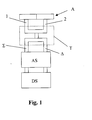
- 2 shows a typical distance Doppler image in the summation channel after the detection of fixed and moving targets.
- the signal powers are plotted over the distance gates and the normalized frequency f / f s .
- the diagram shows clearly that the area of the antenna light spot (bright area), also referred to as the main lobe clutter, is shifted from the Doppler frequency position to zero due to a change in the relative geometry during the illumination time.
- the circles shown in the picture indicate the detected fixed and moving targets.
- the Doppler frequency position of the main lobe clutter is exemplarily at a normalized frequency of 0.2.
- the differential channel signal does not continue is used, the difference channel signal is used in the corresponding MIT radar signal processing this requires, on the one hand, a separation of fixed and moving targets to achieve and on the other hand a repositioning, with respect to the Doppler frequency to carry shifted, moving targets.
- One method for suppressing fixed targets is, for example, the so-called STAP (Space Time Adaptive Processing) method.
- STAP Space Time Adaptive Processing
- the sub-aperture channel signals are exactly the same in amplitude and differ in phase only by a phase value caused by the relative geometry and antenna arrangement.
- To reposition the moving target it is also necessary to compensate for different phase differences between the sub-aperture channel signals, which lead to incorrect positioning.
- a common method for determining the compensation factors of amplitude and phase is the use of defined test signals which are fed into the waveguide part or are radiated in via the antenna. This happens before the radar antenna is actually used.
- the sum and difference channel signals behind the waveguide part are then calculated back into the input signals upstream of the waveguide part, that is to say into the signals of the two sub-aperture channels. If the correction factors have been correctly determined, the two signals are identical.
- the factors are stored in the memory of the digital signal processing and read out from it during use of the radar antenna. Such a method is described by Shunjun W. et al. in "Adaptive Channel Equalization for Space-Time Adaptive Processing"; IEEE International Radar Conference 1995.
- phase difference between the sum and difference channels is determined with the phase correction factor kanal 0 .
- the area of the greatest energy in the sum and difference channel MTI image is preferably used to determine the phase correction factor ⁇ 0 .
- This area of greatest energy is in particular the area of the main lobe of the antenna.
- the calculation of the Doppler frequency position of the main lobe clutter in the first calculation step can use the method in the unpublished patent application DE 101 24 865.2.
- This area is according to the invention adaptively estimated the radar data.
- the correction of the sum and difference channel signals X S (r, t), X D (r, t) in the second calculation step is also referred to as the so-called deramping method.
- the bandwidth reduction is used to reduce the number of signal values, a so-called sampling rate reduction. This is advantageous a reduction in computing time with the same spectral resolution, or advantageous an increase in the spectral resolution with an increase in the number of reduced ones Signal values.
- the sampling rate reduction is carried out in the fourth calculation step.
- the sum and difference channel time signals are located within a distance cell several point targets that differ in amplitude and phase. However, these cannot be resolved in the time signal.
- a transformation of the filtered Sum and difference channel signals in the spectral range the so-called Doppler frequency range carried out.
- the transformation is advantageously carried out using a windowed Fourier Fast Transformation (FFT). It follows that the individual point targets with regard to their frequency, i.e. the time derivative of the Phase can be distinguished.
- FFT windowed Fourier Fast Transformation
- An FFT can be viewed as an arrangement of several frequency subbands become.
- Each frequency subband has an attenuation of approx. 14 dB, corresponding to the impulse response of a rectangular window. It means that Amplitudes of the neighboring frequency band with an attenuation of approx. 14 dB also be allowed through.
- the time signals are advantageous by means of a window function high blocking attenuation, this results in an almost unadulterated spectral signal in every frequency band.
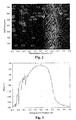
- FIG. 3 shows an example of the phase difference between the sum and difference channel spectrum in the main lobe clutter region, the Doppler frequency position of the main lobe clutter according to FIG. 2 being 0.2.
- FIG. 3 shows a phase difference of -110 ° between the sum and difference channel spectrum for the mean Doppler frequency position of the main lobe clutter.
- This phase difference which can be 90 °, for example, depending on the design of the MagicT, is corrected according to the invention by means of the phase correction factor ⁇ 0 in the spectrum.
- the arithmetic mean of the difference phase values is then calculated in the eighth calculation step within the Doppler frequency position range of the main lobe clutter determined in the first calculation step.
- This mean corresponds to the phase correction factor ⁇ 0 .
- FIG. 4 shows an enlarged section around the Doppler frequency position of the main lobe clutter from FIG. 3.
- a further curve is drawn in, which corresponds to the course of the phase difference between the sum and difference channel spectrum corrected by the phase correction factor a 0 .
- This corrected curve has a phase difference of 0 ° between the sum and difference channel spectrum at the Doppler frequency position of the main lobe clutter.
- the frequency spectra for the two subaperture channels are determined according to equations (1) and (2) by means of the estimated phase correction factor admiri 0, the amplitude correction factor a 0 being set to 1.
- the power density spectra are calculated from the complex frequency spectra and these are advantageously geometrically averaged over a predeterminable selection of distance gates, ie the mean value of the logarithmic powers is calculated.
- the amplitude correction factor a 0 estimated in the second, third and fourth calculation step thus indicates by how much the power density spectra of the two sub-aperture channel spectra constantly deviate from one another, at least in the region of the main lobe clutter.
- the stabilization of the Estimation of the constant phase and amplitude correction factors recursively from Signal pulse package to signal pulse package.
- a frequency distribution of the Estimates are calculated and the value with the greatest frequency is used as an estimate.
- An advantage of the invention is that the sum and difference channel by means of digital Signal processing can be calculated back into the individual channels of the subaperture, without having to make any changes to the antenna (front end). These calculations are done during normal antenna operation, without having to interrupt the coherent signal processing.
- An essential one The advantage of the invention is that no test signal is required for the calculation, but this happens on the radar data itself. In addition, the invention provides Very good procedure even with a bad signal / noise ratio Results.
- Another advantage is that for the method according to the invention no knowledge of the Synchronous properties of the channels is required. If the synchronization differences of the channels are time-dependent, this is due to the adaptivity of the invention Method taken into account by applying the method in every nth calculation step and the estimates are used with the greatest probability.
- the method according to the invention can also be applied to signals other than radar signals transfer.
Landscapes
- Engineering & Computer Science (AREA)
- Remote Sensing (AREA)
- Radar, Positioning & Navigation (AREA)
- Physics & Mathematics (AREA)
- Computer Networks & Wireless Communication (AREA)
- General Physics & Mathematics (AREA)
- Electromagnetism (AREA)
- Radar Systems Or Details Thereof (AREA)
Applications Claiming Priority (2)
| Application Number | Priority Date | Filing Date | Title |
|---|---|---|---|
| DE10146643 | 2001-09-21 | ||
| DE10146643A DE10146643C1 (de) | 2001-09-21 | 2001-09-21 | Verfahren zur Kalibrierung der Radarsignale an den Subaperturen der Antenne eines zweikanaligen SAR/MTI Radarsystems |
Publications (3)
| Publication Number | Publication Date |
|---|---|
| EP1296157A2 true EP1296157A2 (fr) | 2003-03-26 |
| EP1296157A3 EP1296157A3 (fr) | 2003-07-30 |
| EP1296157B1 EP1296157B1 (fr) | 2006-05-31 |
Family
ID=7699850
Family Applications (1)
| Application Number | Title | Priority Date | Filing Date |
|---|---|---|---|
| EP02016541A Expired - Lifetime EP1296157B1 (fr) | 2001-09-21 | 2002-07-24 | Procédé d'étalonnage des signaux radar des sous-ouvertures de l'antenne d'un système radar SAR/MTI à deux voies |
Country Status (3)
| Country | Link |
|---|---|
| US (1) | US6686874B2 (fr) |
| EP (1) | EP1296157B1 (fr) |
| DE (2) | DE10146643C1 (fr) |
Cited By (9)
| Publication number | Priority date | Publication date | Assignee | Title |
|---|---|---|---|---|
| CN100526912C (zh) * | 2006-06-02 | 2009-08-12 | 中国科学院电子学研究所 | 一种宽带合成孔径雷达的有源外定标器及其定标方法 |
| CN101236247B (zh) * | 2008-03-07 | 2010-06-16 | 北京航空航天大学 | 一种星载多通道天线sar数据通道幅相误差校正平台 |
| CN101082666B (zh) * | 2006-06-02 | 2011-07-27 | 中国科学院电子学研究所 | 基于自动测试系统实现对雷达脉冲信号高精度调制的方法 |
| CN103176172A (zh) * | 2013-02-06 | 2013-06-26 | 中国科学院电子学研究所 | 一种机载干涉sar基于同步内定标信号的相位测量补偿方法 |
| CN111352101A (zh) * | 2018-12-20 | 2020-06-30 | 中国人民解放军空军预警学院 | 一种相控阵机载雷达空时二维数字差通道形成方法 |
| KR20200107380A (ko) * | 2019-03-07 | 2020-09-16 | 주식회사 만도 | 레이더 장치, 레이더 장치의 제어 방법 및 레이더 장치를 이용한 감지 시스템 |
| CN112068086A (zh) * | 2020-10-17 | 2020-12-11 | 中国电波传播研究所(中国电子科技集团公司第二十二研究所) | 一种基于外定标试验数据的岸基多通道雷达幅相校正方法 |
| CN112698320A (zh) * | 2020-12-07 | 2021-04-23 | 南京工业职业技术大学 | 一种动目标检测滤波器组的优化设计方法 |
| CN115015920A (zh) * | 2022-02-28 | 2022-09-06 | 西安电子科技大学 | 一种基于距离空变频谱矫正的快速后向投影成像方法 |
Families Citing this family (15)
| Publication number | Priority date | Publication date | Assignee | Title |
|---|---|---|---|---|
| US20030065296A1 (en) * | 2001-02-26 | 2003-04-03 | Kaiser Thomas A. | Absorbent material of water absorbent polymer, thermoplastic polymer, and water and method for making same |
| US6879279B2 (en) * | 2003-01-14 | 2005-04-12 | The Regents Of The University Of California | Differential optical synthetic aperture radar |
| ES2314487T3 (es) * | 2004-11-26 | 2009-03-16 | Saab Ab | Rechazo del lobulo trasero de antena. |
| JO3058B1 (ar) | 2005-04-29 | 2017-03-15 | Applied Molecular Evolution Inc | الاجسام المضادة لمضادات -اي ال-6,تركيباتها طرقها واستعمالاتها |
| US20090278732A1 (en) * | 2006-04-28 | 2009-11-12 | Paul Antonik | Method and apparatus for simultaneous synthetic aperture radar and moving target indication |
| US7646326B2 (en) * | 2006-04-28 | 2010-01-12 | The United States Of America As Represented By The Secretary Of The Air Force | Method and apparatus for simultaneous synthetic aperture radar and moving target indication |
| CN101950016A (zh) * | 2010-09-30 | 2011-01-19 | 重庆长安汽车股份有限公司 | 一种汽车倒车雷达系统耐久性试验装置 |
| CN103885053B (zh) * | 2014-03-27 | 2016-07-06 | 中国电子科技集团公司第二十八研究所 | 一种基于追踪滤波器的雷达数据动目标检测处理方法 |
| CN113287036B (zh) * | 2019-09-30 | 2022-09-09 | 华为技术有限公司 | 一种速度解模糊的方法及回波信号处理装置 |
| CN111123221B (zh) * | 2019-12-12 | 2021-11-23 | 上海卫星工程研究所 | 有源相控阵体制sar通道全链路幅相稳定性测试方法 |
| JP7351794B2 (ja) * | 2020-05-19 | 2023-09-27 | 三菱電機株式会社 | 合成開口レーダシステム |
| CN111638494B (zh) * | 2020-05-31 | 2022-09-02 | 西南电子技术研究所(中国电子科技集团公司第十研究所) | 数字波束合成系统多通道幅相校正方法 |
| CN113419240B (zh) * | 2021-04-26 | 2023-05-16 | 中国科学院空天信息创新研究院 | 基于双通道sar的动目标检测方法,双通道sar及存储介质 |
| CN113295287B (zh) * | 2021-05-26 | 2022-11-11 | 中国科学院光电技术研究所 | 一种针对光瞳动态强度分布的哈特曼子孔径减阈值方法 |
| CN114442080B (zh) * | 2022-01-29 | 2023-10-20 | 南京隼眼电子科技有限公司 | 运动目标速度解模糊方法、装置、电子设备及存储介质 |
Family Cites Families (8)
| Publication number | Priority date | Publication date | Assignee | Title |
|---|---|---|---|---|
| US3794998A (en) * | 1972-04-26 | 1974-02-26 | Raytheon Co | Monopulse radar receiver with error correction |
| US4005421A (en) * | 1973-05-30 | 1977-01-25 | Westinghouse Electric Corporation | Monopulse radar system and method for improved low elevation tracking |
| US4368468A (en) * | 1980-12-22 | 1983-01-11 | Westinghouse Electric Corp. | Monopulse radio receiver compensation apparatus |
| US5245347A (en) * | 1980-12-29 | 1993-09-14 | Raytheon Company | All weather tactical strike system (AWTSS) and method of operation |
| FR2595144B1 (fr) * | 1986-02-28 | 1988-05-13 | Thomson Csf | Procede de traitement des signaux somme et difference d'un radar du type monopulse, en vue d'estimer la phase parasite introduite entre ces signaux par les circuits hyperfrequence de formation des voies somme et difference |
| US5051752A (en) * | 1990-11-05 | 1991-09-24 | Hughes Aircraft Company | Angle measurement compensation technique for amplitude comparison monopulse receiver |
| US6124824A (en) * | 1999-01-29 | 2000-09-26 | Cwill Telecommunications, Inc. | Adaptive antenna array system calibration |
| US6144333A (en) * | 1999-08-13 | 2000-11-07 | Raytheon Company | Method for estimating gain and phase imbalance using self-calibrating monopulse angle discriminants in a monopulse radar system |
-
2001
- 2001-09-21 DE DE10146643A patent/DE10146643C1/de not_active Expired - Fee Related
-
2002
- 2002-07-24 EP EP02016541A patent/EP1296157B1/fr not_active Expired - Lifetime
- 2002-07-24 DE DE50206976T patent/DE50206976D1/de not_active Expired - Lifetime
- 2002-09-23 US US10/252,005 patent/US6686874B2/en not_active Expired - Fee Related
Cited By (12)
| Publication number | Priority date | Publication date | Assignee | Title |
|---|---|---|---|---|
| CN100526912C (zh) * | 2006-06-02 | 2009-08-12 | 中国科学院电子学研究所 | 一种宽带合成孔径雷达的有源外定标器及其定标方法 |
| CN101082666B (zh) * | 2006-06-02 | 2011-07-27 | 中国科学院电子学研究所 | 基于自动测试系统实现对雷达脉冲信号高精度调制的方法 |
| CN101236247B (zh) * | 2008-03-07 | 2010-06-16 | 北京航空航天大学 | 一种星载多通道天线sar数据通道幅相误差校正平台 |
| CN103176172A (zh) * | 2013-02-06 | 2013-06-26 | 中国科学院电子学研究所 | 一种机载干涉sar基于同步内定标信号的相位测量补偿方法 |
| CN111352101A (zh) * | 2018-12-20 | 2020-06-30 | 中国人民解放军空军预警学院 | 一种相控阵机载雷达空时二维数字差通道形成方法 |
| CN111352101B (zh) * | 2018-12-20 | 2023-08-18 | 中国人民解放军空军预警学院 | 一种相控阵机载雷达空时二维数字差通道形成方法 |
| KR20200107380A (ko) * | 2019-03-07 | 2020-09-16 | 주식회사 만도 | 레이더 장치, 레이더 장치의 제어 방법 및 레이더 장치를 이용한 감지 시스템 |
| CN112068086A (zh) * | 2020-10-17 | 2020-12-11 | 中国电波传播研究所(中国电子科技集团公司第二十二研究所) | 一种基于外定标试验数据的岸基多通道雷达幅相校正方法 |
| CN112068086B (zh) * | 2020-10-17 | 2022-03-01 | 中国电波传播研究所(中国电子科技集团公司第二十二研究所) | 一种基于外定标试验数据的岸基多通道雷达幅相校正方法 |
| CN112698320A (zh) * | 2020-12-07 | 2021-04-23 | 南京工业职业技术大学 | 一种动目标检测滤波器组的优化设计方法 |
| CN112698320B (zh) * | 2020-12-07 | 2023-10-24 | 南京工业职业技术大学 | 一种动目标检测滤波器组的优化设计方法 |
| CN115015920A (zh) * | 2022-02-28 | 2022-09-06 | 西安电子科技大学 | 一种基于距离空变频谱矫正的快速后向投影成像方法 |
Also Published As
| Publication number | Publication date |
|---|---|
| US20030058159A1 (en) | 2003-03-27 |
| EP1296157A3 (fr) | 2003-07-30 |
| US6686874B2 (en) | 2004-02-03 |
| DE50206976D1 (de) | 2006-07-06 |
| EP1296157B1 (fr) | 2006-05-31 |
| DE10146643C1 (de) | 2003-08-14 |
Similar Documents
| Publication | Publication Date | Title |
|---|---|---|
| EP1296157B1 (fr) | Procédé d'étalonnage des signaux radar des sous-ouvertures de l'antenne d'un système radar SAR/MTI à deux voies | |
| DE102018102816B3 (de) | Radar mit phasenkorrektur | |
| DE102018132745B4 (de) | Fmcw radar mit störsignalunterdrückung im zeitbereich | |
| EP0795762B1 (fr) | Procédé de mise à l'échelle de l'azimut pour données SAR et processeur à grande précision pour traitement des données SCAN-SAR | |
| DE102012021010B4 (de) | Synthetisches Apertur Radar zur gleichzeitigen Bildaufnahme und Bewegtzielerkennung | |
| DE19757309C1 (de) | Verfahren zur Verarbeitung von Spotlight SAR-Rohdaten | |
| DE19822957C1 (de) | Verfahren zur Detektion und Unterdrückung von Störsignalen in SAR-Daten und Einrichtung zur Durchführung des Verfahrens | |
| DE102018123383A1 (de) | Radarerfassung mit Störungsunterdrückung | |
| EP0533220B1 (fr) | Méthode pour distinguer au moins deux objectifs spécialement pour radars Doppler HPRF | |
| DE102017207604B4 (de) | Radarsystem mit Überwachung der Frequenzmodulation einer Folge von gleichartigen Sendesignalen | |
| DE69214257T2 (de) | Verbessertes ISAR Bilderzeugungsradarsystem | |
| EP0492132B1 (fr) | Procédé pour générer de manière numérique des images-SAR et appareil pour exécuter le procédé | |
| EP3385750A1 (fr) | Procédé et dispositif de traitement de données brutes sar | |
| EP4196818B1 (fr) | Procédé et dispositif permettant de déterminer des perturbations de fréquence dans un signal reçu d'un système sar à canaux multiples actif | |
| DE2752338C2 (de) | Radarempfänger | |
| DE3520398C2 (fr) | ||
| EP1184680B1 (fr) | Méthode pour repositioner des cibles en mouvement dans des images SAR | |
| EP1286415B1 (fr) | Procédé de suppression de signaux de brouillage | |
| EP1034630A1 (fr) | Procede et dispositif pour mesurer les caracteristiques de voies de radiocommunication | |
| EP1134592B1 (fr) | Filtre STAP temps réel pour suppression de cible fixe | |
| DE102021207032A1 (de) | SA-Radarsensor für Kraftfahrzeuge | |
| DE4117849C2 (de) | Verfahren zur Generierung einer Referenzfunktion für eine Impulskompression von frequenz-, phasen- und/oder amplitudenmodulierten Signalen | |
| DE102006007025A1 (de) | Vorrichtung zum Detektieren einer Signalart | |
| DE102018221285A1 (de) | Verfahren zur Interferenzunterdrückung und Verfahren zur Signalwiederherstellung | |
| EP3082273A1 (fr) | Procédé et dispositif de réduction de signaux parasites corrélés dans des systèmes de réception multi-canaux à formation de faisceau numérique |
Legal Events
| Date | Code | Title | Description |
|---|---|---|---|
| PUAI | Public reference made under article 153(3) epc to a published international application that has entered the european phase |
Free format text: ORIGINAL CODE: 0009012 |
|
| AK | Designated contracting states |
Kind code of ref document: A2 Designated state(s): AT BE BG CH CY CZ DE DK EE ES FI FR GB GR IE IT LI LU MC NL PT SE SK TR |
|
| AX | Request for extension of the european patent |
Extension state: AL LT LV MK RO SI |
|
| PUAL | Search report despatched |
Free format text: ORIGINAL CODE: 0009013 |
|
| AK | Designated contracting states |
Designated state(s): AT BE BG CH CY CZ DE DK EE ES FI FR GB GR IE IT LI LU MC NL PT SE SK TR |
|
| AX | Request for extension of the european patent |
Extension state: AL LT LV MK RO SI |
|
| 17P | Request for examination filed |
Effective date: 20040122 |
|
| AKX | Designation fees paid |
Designated state(s): DE FR GB IT |
|
| 17Q | First examination report despatched |
Effective date: 20050426 |
|
| GRAP | Despatch of communication of intention to grant a patent |
Free format text: ORIGINAL CODE: EPIDOSNIGR1 |
|
| GRAS | Grant fee paid |
Free format text: ORIGINAL CODE: EPIDOSNIGR3 |
|
| GRAA | (expected) grant |
Free format text: ORIGINAL CODE: 0009210 |
|
| AK | Designated contracting states |
Kind code of ref document: B1 Designated state(s): DE FR GB IT |
|
| REG | Reference to a national code |
Ref country code: GB Ref legal event code: FG4D Free format text: NOT ENGLISH |
|
| REF | Corresponds to: |
Ref document number: 50206976 Country of ref document: DE Date of ref document: 20060706 Kind code of ref document: P |
|
| GBT | Gb: translation of ep patent filed (gb section 77(6)(a)/1977) |
Effective date: 20060920 |
|
| ET | Fr: translation filed | ||
| PLBE | No opposition filed within time limit |
Free format text: ORIGINAL CODE: 0009261 |
|
| STAA | Information on the status of an ep patent application or granted ep patent |
Free format text: STATUS: NO OPPOSITION FILED WITHIN TIME LIMIT |
|
| 26N | No opposition filed |
Effective date: 20070301 |
|
| PGFP | Annual fee paid to national office [announced via postgrant information from national office to epo] |
Ref country code: FR Payment date: 20110729 Year of fee payment: 10 |
|
| PGFP | Annual fee paid to national office [announced via postgrant information from national office to epo] |
Ref country code: GB Payment date: 20110721 Year of fee payment: 10 Ref country code: DE Payment date: 20110722 Year of fee payment: 10 |
|
| PGFP | Annual fee paid to national office [announced via postgrant information from national office to epo] |
Ref country code: IT Payment date: 20110725 Year of fee payment: 10 |
|
| GBPC | Gb: european patent ceased through non-payment of renewal fee |
Effective date: 20120724 |
|
| REG | Reference to a national code |
Ref country code: FR Ref legal event code: ST Effective date: 20130329 |
|
| PG25 | Lapsed in a contracting state [announced via postgrant information from national office to epo] |
Ref country code: FR Free format text: LAPSE BECAUSE OF NON-PAYMENT OF DUE FEES Effective date: 20120731 Ref country code: GB Free format text: LAPSE BECAUSE OF NON-PAYMENT OF DUE FEES Effective date: 20120724 Ref country code: DE Free format text: LAPSE BECAUSE OF NON-PAYMENT OF DUE FEES Effective date: 20130201 |
|
| PG25 | Lapsed in a contracting state [announced via postgrant information from national office to epo] |
Ref country code: IT Free format text: LAPSE BECAUSE OF NON-PAYMENT OF DUE FEES Effective date: 20120724 |
|
| REG | Reference to a national code |
Ref country code: DE Ref legal event code: R119 Ref document number: 50206976 Country of ref document: DE Effective date: 20130201 |