EP1297992A2 - Verfahren und Vorrichtung zur Regelung eines elektrischen Fahrzeuges - Google Patents
Verfahren und Vorrichtung zur Regelung eines elektrischen Fahrzeuges Download PDFInfo
- Publication number
- EP1297992A2 EP1297992A2 EP02021752A EP02021752A EP1297992A2 EP 1297992 A2 EP1297992 A2 EP 1297992A2 EP 02021752 A EP02021752 A EP 02021752A EP 02021752 A EP02021752 A EP 02021752A EP 1297992 A2 EP1297992 A2 EP 1297992A2
- Authority
- EP
- European Patent Office
- Prior art keywords
- electric vehicle
- controlling
- synchronous motor
- signal
- current
- Prior art date
- Legal status (The legal status is an assumption and is not a legal conclusion. Google has not performed a legal analysis and makes no representation as to the accuracy of the status listed.)
- Withdrawn
Links
- 238000000034 method Methods 0.000 title claims abstract description 18
- 230000001360 synchronised effect Effects 0.000 claims abstract description 51
- 230000001133 acceleration Effects 0.000 claims abstract description 16
- 238000004804 winding Methods 0.000 claims abstract description 13
- 238000001514 detection method Methods 0.000 claims description 15
- 239000003990 capacitor Substances 0.000 claims description 9
- 238000006243 chemical reaction Methods 0.000 claims description 4
- 230000001939 inductive effect Effects 0.000 claims description 4
- 238000010276 construction Methods 0.000 description 8
- XEEYBQQBJWHFJM-UHFFFAOYSA-N Iron Chemical group [Fe] XEEYBQQBJWHFJM-UHFFFAOYSA-N 0.000 description 6
- 230000004907 flux Effects 0.000 description 2
- 238000009499 grossing Methods 0.000 description 2
- 230000004048 modification Effects 0.000 description 2
- 238000012986 modification Methods 0.000 description 2
- 230000003213 activating effect Effects 0.000 description 1
- 230000003467 diminishing effect Effects 0.000 description 1
- 230000008030 elimination Effects 0.000 description 1
- 238000003379 elimination reaction Methods 0.000 description 1
- 229910052761 rare earth metal Inorganic materials 0.000 description 1
Images


Classifications
-
- B—PERFORMING OPERATIONS; TRANSPORTING
- B60—VEHICLES IN GENERAL
- B60L—PROPULSION OF ELECTRICALLY-PROPELLED VEHICLES; SUPPLYING ELECTRIC POWER FOR AUXILIARY EQUIPMENT OF ELECTRICALLY-PROPELLED VEHICLES; ELECTRODYNAMIC BRAKE SYSTEMS FOR VEHICLES IN GENERAL; MAGNETIC SUSPENSION OR LEVITATION FOR VEHICLES; MONITORING OPERATING VARIABLES OF ELECTRICALLY-PROPELLED VEHICLES; ELECTRIC SAFETY DEVICES FOR ELECTRICALLY-PROPELLED VEHICLES
- B60L7/00—Electrodynamic brake systems for vehicles in general
- B60L7/003—Dynamic electric braking by short circuiting the motor
-
- B—PERFORMING OPERATIONS; TRANSPORTING
- B60—VEHICLES IN GENERAL
- B60L—PROPULSION OF ELECTRICALLY-PROPELLED VEHICLES; SUPPLYING ELECTRIC POWER FOR AUXILIARY EQUIPMENT OF ELECTRICALLY-PROPELLED VEHICLES; ELECTRODYNAMIC BRAKE SYSTEMS FOR VEHICLES IN GENERAL; MAGNETIC SUSPENSION OR LEVITATION FOR VEHICLES; MONITORING OPERATING VARIABLES OF ELECTRICALLY-PROPELLED VEHICLES; ELECTRIC SAFETY DEVICES FOR ELECTRICALLY-PROPELLED VEHICLES
- B60L50/00—Electric propulsion with power supplied within the vehicle
- B60L50/50—Electric propulsion with power supplied within the vehicle using propulsion power supplied by batteries or fuel cells
- B60L50/60—Electric propulsion with power supplied within the vehicle using propulsion power supplied by batteries or fuel cells using power supplied by batteries
-
- A—HUMAN NECESSITIES
- A61—MEDICAL OR VETERINARY SCIENCE; HYGIENE
- A61G—TRANSPORT, PERSONAL CONVEYANCES, OR ACCOMMODATION SPECIALLY ADAPTED FOR PATIENTS OR DISABLED PERSONS; OPERATING TABLES OR CHAIRS; CHAIRS FOR DENTISTRY; FUNERAL DEVICES
- A61G5/00—Chairs or personal conveyances specially adapted for patients or disabled persons, e.g. wheelchairs
- A61G5/06—Chairs or personal conveyances specially adapted for patients or disabled persons, e.g. wheelchairs with obstacle mounting facilities, e.g. for climbing stairs, kerbs or steps
-
- B—PERFORMING OPERATIONS; TRANSPORTING
- B60—VEHICLES IN GENERAL
- B60L—PROPULSION OF ELECTRICALLY-PROPELLED VEHICLES; SUPPLYING ELECTRIC POWER FOR AUXILIARY EQUIPMENT OF ELECTRICALLY-PROPELLED VEHICLES; ELECTRODYNAMIC BRAKE SYSTEMS FOR VEHICLES IN GENERAL; MAGNETIC SUSPENSION OR LEVITATION FOR VEHICLES; MONITORING OPERATING VARIABLES OF ELECTRICALLY-PROPELLED VEHICLES; ELECTRIC SAFETY DEVICES FOR ELECTRICALLY-PROPELLED VEHICLES
- B60L2220/00—Electrical machine types; Structures or applications thereof
- B60L2220/10—Electrical machine types
- B60L2220/14—Synchronous machines
-
- Y—GENERAL TAGGING OF NEW TECHNOLOGICAL DEVELOPMENTS; GENERAL TAGGING OF CROSS-SECTIONAL TECHNOLOGIES SPANNING OVER SEVERAL SECTIONS OF THE IPC; TECHNICAL SUBJECTS COVERED BY FORMER USPC CROSS-REFERENCE ART COLLECTIONS [XRACs] AND DIGESTS
- Y02—TECHNOLOGIES OR APPLICATIONS FOR MITIGATION OR ADAPTATION AGAINST CLIMATE CHANGE
- Y02T—CLIMATE CHANGE MITIGATION TECHNOLOGIES RELATED TO TRANSPORTATION
- Y02T10/00—Road transport of goods or passengers
- Y02T10/60—Other road transportation technologies with climate change mitigation effect
- Y02T10/70—Energy storage systems for electromobility, e.g. batteries
-
- Y—GENERAL TAGGING OF NEW TECHNOLOGICAL DEVELOPMENTS; GENERAL TAGGING OF CROSS-SECTIONAL TECHNOLOGIES SPANNING OVER SEVERAL SECTIONS OF THE IPC; TECHNICAL SUBJECTS COVERED BY FORMER USPC CROSS-REFERENCE ART COLLECTIONS [XRACs] AND DIGESTS
- Y02—TECHNOLOGIES OR APPLICATIONS FOR MITIGATION OR ADAPTATION AGAINST CLIMATE CHANGE
- Y02T—CLIMATE CHANGE MITIGATION TECHNOLOGIES RELATED TO TRANSPORTATION
- Y02T10/00—Road transport of goods or passengers
- Y02T10/60—Other road transportation technologies with climate change mitigation effect
- Y02T10/72—Electric energy management in electromobility
Definitions
- the present invention relates to a method and an apparatus of controlling an electric vehicle.
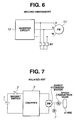
- Fig. 7 shows a schematic of construction of an electric vehicle in commercial use.
- a chopper 3 connects to a battery 1 by way of a magnet switch 2.
- a battery voltage is converted from direct current (hereinafter referred to as "DC") to DC by the chopper. Then, the thus converted voltage is supplied to a direct current motor 4 which is subjected to control.
- the direct current motor 4 has a rotary shaft connecting to a tire 6 by way of a speed reduction gear 5.
- Also shown in Fig. 7 includes an electromagnetic brake 7.
- the electric vehicle may take the following operations:
- the magnet switch 2 keeps turned on during travel of the electric vehicle.
- the driver stops operating the accelerator, to thereby reduce the direct current motor 4 in speed. Then, the direct current motor 4 reaching substantially 0 in speed opens an exciting coil of the electromagnetic brake 7, thus generating a braking force (torque) to a brake system for allowing the electric vehicle to make a complete stop. Together with the stop of the electric vehicle, the chopper 3 stops operation.
- opening the exciting coil of the electromagnetic brake 7 allows an exciting current to become 0, allowing the electromagnetic brake 7 to have a spring force for braking operation.
- the construction according to the related art in Fig. 7 requires energization of the exciting coil of the electromagnetic brake 7, so as to release the braking force (torque) caused by the spring force.
- the above description is required for securing the braking force (torque) for the electromagnetic brake 7, so as to prevent a possible failure of the electromagnetic brake 7 and a control circuit.
- the electric vehicle having the battery 1 as a driving power source has to continuously keep supplying exciting current to the electromagnetic brake 7 during travel of the electric vehicle.
- Power consumption attributable to the continuous supply of the exciting current to the electromagnetic brake 7 is about 30% of a motor current consumed when the electric vehicle is making a flat traveling. Considering energy efficiency, the figure 30% is not ignorable (minor).
- the direct current motor 4 is preferred as small as possible.
- the speed reduction gear 5 (gear type). Setting the speed reduction gear 5 is responsible for greater capacity of the battery 1, which is also disadvantageous in terms of efficiency as well as energy saving.
- Diminishing the gear of the speed reduction gear 5 in size may give damage to teeth of the gear.
- the electric vehicle may be inconvenient especially for those who are physically disabled or week, for the following causes:
- a method of controlling an electric vehicle which is so constituted as to drive a synchronous motor by way of a switch and an inverter circuit.
- a battery acts as a source of driving a controlling power.
- the synchronous motor has a permanent magnet acting as an outer rotor. The method comprises the following operations of:
- an apparatus of controlling an electric vehicle comprising:
- the controller comprises:
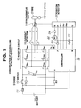
- FIG. 1 there is provided a construction of an apparatus of controlling an electric vehicle, according to a first embodiment of the present invention.
- a battery 10 acting as a power source connects to an inverter circuit 13 by way of a fuse 11 and a switch 12 (such as breaker, key switch and the like).
- the inverter circuit 13 is constituted of three phases, including a switching element TRU, a switching element TRV, a switching element TRW, a switching element TRX, a switching element TRY and a switching element TRZ.
- a first arm connecting the switching element TRU and the switching element TRX has a first bridge contact connecting to a phase terminal U of a synchronous motor 14.
- a second arm connecting the switching element TRV and the switching element TRY has a second bridge contact connecting to a phase terminal V of the synchronous motor 14.
- a third arm connecting the switching element TRW and the switching element TRZ has a third bridge contact connecting to a phase terminal W of the synchronous motor 14.
- the synchronous motor 14 is of 3-phase type and has a permanent magnet 46 (to be described more in detail afterward referring to Fig. 3) as outer rotor.
- the outer rotor of the synchronous motor 14 is of a direct drive type which is embedded in a wheel 45 (to be described afterward referring to Fig. 3).
- the permanent magnet 46 is made of rare earth element featuring a high performance.
- the synchronous motor 14 is small in size and generates a great force (torque).
- a current detector 16 which connects to the phase terminal U and the phase terminal W.
- a smoothing capacitor 17 for the inverter circuit 13 are in parallel with the battery 10.
- a diode 18 connecting in parallel with the switch 12.
- a position detector 20 made of a Hall element 49 (to be described more in detail referring to Fig. 3).
- the position detector 20 detects a position of the permanent magnet 46 (outer rotor) of the synchronous motor 14.
- the position detector 20 outputs a position signal Hu, a position signal Hv and a position signal Hw which are used for switching polarity of a current in the synchronous motor 14.
- the switching operation by the position detector 20 is carried out by way of a controller 30 and the inverter circuit 13.
- the Hall element 49 of the position detector 20 is a detector element used for switching the polarity of the current in the synchronous motor 14, corresponding to the position of the permanent magnet 46 (outer rotor).
- a first power source terminal P a second power source terminal N, a diode 21, a relay 22 and a contact 24.
- the relay 22 in series with the contact 24 is connected between the first power source terminal P and the second power source terminal N. Energizing the relay 22 can turn on a contact RY of the relay 22, to thereby allow the battery 10 to supply a voltage to the controller 30 for controlling purpose.
- the contact 24 is a switching element which can be turned on when the switch 12 is turned off. Thereby, when the electric vehicle is travelling with the switch 12 turned on, the relay 22 is deenergized.
- the double layer capacitor 23 which can be a general electrolytic capacitor.
- the double layer capacitor 23 has the following features (advantages): 1. Great electrostatic capacity. 2. Low impedance generating heavy current. 3. Small in size. 4. Light in weight. 5. Longevity. 6. Rechargeable in a short time.
- the controller 30 is a microcomputer. As is seen in Fig. 2, the controller 30 is constituted of a speed detector 31, a proportional integral controller 32 (hereinafter referred to as "PI controller 32"), a brake speed detector 33, a 3/2 phase coordinate converter 34, an optimum current command operator 35, a d/q-axis current controller 36, a dead time compensator 37, a 2/3 phase coordinate converter 38, and a pulse width modulation signal generator 39 (hereinafter referred to as "PWM signal generator 39").
- PI controller 32 proportional integral controller 32
- brake speed detector 33 a brake speed detector 33
- 3/2 phase coordinate converter 34 an optimum current command operator 35
- a d/q-axis current controller 36 a d/q-axis current controller 36
- a dead time compensator 37 a dead time compensator 37
- 2/3 phase coordinate converter 38 a pulse width modulation signal generator 39
- the speed detector 31 receives the position signal Hu, the position signal Hv and the position signal Hw from the position detector 20.
- the PI controller 32 receives an acceleration signal corresponding to an angle of an accelerator Acc (accelerator pedal).
- the brake speed detector 33 receives the acceleration signal from the accelerator Acc, and a speed signal ⁇ from the speed detector 31.
- the brake speed detector 33 has the following function:
- the 3/2 phase coordinate converter 34 receives the speed signal ⁇ from the speed detector 31, and a current signal Iu and a current signal Iw from the current detector 16, and then converts them from 3-phase coordinate to 2-phase coordinate.
- the optimum current command operator 35 operates a current command after receiving the speed signal ⁇ from the speed detector 31, a brake detection signal from the brake speed detector 33, and a torque command from the PI controller 32.
- the d/q-axis current controller 36 controls a d/q-axis current after receiving the following signals:
- the battery 10 (control power source) supplies the controller 30 with a controlling power by way of a terminal which is disposed at the switch 12 and disposed on an opposite side to the battery 10.
- the controlling power can be supplied by way of the contact RY of the relay 22.
- an axle shaft 40 to which a support section 41 is fixed.
- a stator iron core 42 which is fixed to the support section 41.
- the stator iron core 42 has an outer periphery formed with a slot.
- a stator winding 43 is disposed in the slot.
- the stator iron core 42 and the stator winding 43 are in combination referred to as a stator 50.
- the wheel 45 is fitted to the bearing 44 in such a manner as to wrap a fixed side of the stator 50 and the like.
- the permanent magnet 46 (outer rotor) is disposed circumferentially around the stator iron core 42, defining therebetween a gap. N-poles and P-poles of the permanent magnet 46 are arranged alternately. In sum, the permanent magnet 46 (outer rotor) and the stator 50 constitute the 3-phase type synchronous motor 14.
- a tire 15 which is fitted to the wheel 45 on an outer periphery of the permanent magnet 46.
- a mount plate 48 to draw in a terminal of the stator winding 43 which is disposed in the slot of the stator iron core 42.
- the Hall element 49 of the position detector 20 is also fixed to the mount plate 48.
- a magnet 47 which is disposed on an inside (of the wheel 45) opposing the Hall element 49.
- the driver steps on the accelerator Acc. Then, the acceleration signal is outputted to the PI controller 32.
- the speed signal ⁇ is 0.
- the acceleration signal is inputted to the PI controller 32 with no modification, to thereby calculate the torque command.
- the position detector 20 detects the position signal Hu, the position signal Hv and the position signal Hw which are inputted to the speed detector 31 of the controller 30 so as to obtain the speed signal ⁇ .
- the thus obtained speed signal ⁇ is added to the acceleration signal from the accelerator Acc.
- the thus obtained differential (deviation) signal is inputted to the PI controller 32, to thereby calculate the torque command which is then outputted to the optimum current command operator 35.
- the speed signal ⁇ is also inputted to the optimum current command operator 35.
- the torque command and the speed signal ⁇ contribute to calculation of an optimum current.
- the optimum current command operator 35 makes a conversion to two axes, that is, the current signal Id*1 (magnetic flux element current Id*1) and the current signal Iq*1 (torque element current Iq*1).
- the thus converted current signal Id*1 and the current signal Iq*1 are outputted to the dead time compensator 37 and the d/q-axis current controller 36.
- the d/q-axis current controller 36 receives the speed signal ⁇ from the speed detector 31 and a current signal Id*2 and a current signal Iq*2 from the 3/2 phase coordinate converter 34, to thereby calculate a 2-axis voltage, that is, a voltage signal Vd* and a voltage signal Vq*.
- the thus calculated voltage signal Vd* and a voltage signal Vq* are outputted to the 2/3 phase coordinate converter 38 for conversion to three phases. Then, turning "on” or “off” each of the switching element TRU, the switching element TRV, the switching element TRW, the switching element TRX, the switching element TRY and the switching element TRZ of the inverter circuit 13 can supply the current to the synchronous motor 14.
- the synchronous motor 14 is of 3-phase type and has the permanent magnet 46 as outer rotor. In other words, turning the synchronous motor 14 can turn the permanent magnet 46, to thereby generate an attraction and repulsion between the permanent magnet 46 and the stator winding 43. Positioning the permanent magnet 46 (outer rotor) by means of the thus generated attraction and repulsion can switch directions of the current flowing in the stator winding 43, to thereby keep rotation of the permanent magnet 46 (outer rotor).
- the current of the synchronous motor 14 can be detected by the current detector 16 which connects to the phase terminal U and the phase terminal W.
- the thus detected current can be fedback to the 3/2 phase coordinate converter 34 respectively as the current signal Iu and the current signal Iw.
- the controller 30 of the inverter circuit 13 carries out controlling operation by calculating the torque command for speed reduction, so as to generate a braking force (torque). As a result, the synchronous motor 14 is reduced in speed (rotation).
- the brake speed detector 33 detects that the actual speed of the electric vehicle is less than the predetermined % of the rated speed (Herein, the predetermined % is 10%. Preferably, the predetermined % is in a range from 5% to less than 8%. More preferably, the predetermined % is 5%).
- the thus detected brake detection signal is outputted to the optimum current command operator 35. In addition to this operation, the thus detected brake detection signal is outputted to the PWM signal generator 39 as a fixed phase conductive signal.
- the optimum current command operator 35 defines the current signal Iq*1 as a braking force (torque) current, so as to generate an optimum braking force (torque) current.
- the PWM signal generator 39 selects, for example, only the switching element TRU, the switching element TRY and the switching element TRZ of the inverter circuit 13, and then turns on the switching element TRU, the switching element TRY and the switching element TRZ thus selected. With this, the current can flow in the stator winding 43 of a fixed phase of the synchronous motor 14, to thereby generate the braking force (torque).
- the thus generated braking force can be maximized when a polarity of a magnetic flux of the stator iron core 42 faces a reversed polarity of the permanent magnet 46 (outer rotor).
- the attraction between the stator 50 and the permanent magnet 46 (outer rotor) is maximized, to thereby stop rotation of the permanent magnet 46 (outer rotor).
- Fig. 4 shows a graph of the braking force (torque) generated when the fixed phase of the synchronous motor 14 is energized.
- the ordinate of the graph in Fig. 4 is the generated braking force (torque) divided by a rated torque, while the abscissa of the graph in Fig. 4 is the current supplied to the fixed phase of the synchronous motor 14 divided by a rated current.
- the braking force (torque) generated when the fixed phase of the synchronous motor 14 is energized is substantially in proportion to the current supplied to the synchronous motor 14.
- selecting the switching element namely, the switching element TRU, the switching element TRV, the switching element TRW, the switching element TRX, the switching element TRY and the switching element TRZ
- selecting the switching element namely, the switching element TRU, the switching element TRV, the switching element TRW, the switching element TRX, the switching element TRY and the switching element TRZ
- switching element TRU is selected from the power supply side ⁇ although the switching element TRY and the switching element TRZ which are disposed on the negative arm (pole) are turned on ⁇ . Switching the switching element TRU can control the current, to thereby keep the electric vehicle stopped.
- the driver may lock the wheel 45 with a hand brake 19, and thereby turn off the switch 12 (open). With this, the current is not supplied from the inverter circuit 13 to the synchronous motor 14, thus eliminating the braking force (torque) between the stator 50 and the permanent magnet 46 (outer rotor).
- the turned off switch 12 (open) can keep the contact 24 turned on (closed). With the contact 24 thus turned on (closed), the current can flow to the relay 22. In this case, a voltage charged in the double layer capacitor 23 can act as a power source of the thus flowing current. As a result, the relay 22 is energized, and thereby closes the contact RY. Thereby, the controlling power can be supplied again to the controller 30 by way of the contact RY of the relay 22. Thereby, the controlling power can be secured for the controller 30 and the position detector 20.
- the accidental travel of the electric vehicle may cause an inductive voltage to the stator winding 43 of the synchronous motor 14.
- the inductive voltage may cause a short circuit current Iu, a short circuit current Iv and a short circuit current Iw, thus generating the braking force (torque).
- the driver's safety can be assured even when the driver fails to use (apply or activate) the hand brake 19 on the slope. Not causing acceleration, the electric vehicle in this case can make eased and repeated operations, that is, travels and stops, so as to assure the driver's safety.
- the short circuits in Fig. 5 can be caused to the phase terminal V, the phase terminal V and the phase terminal W of the synchronous motor 14 by turning on respectively the switching element TRX, the switching element TRY and the switching element TRZ of the inverter circuit 13.
- FIG. 6 there is provided a construction of the apparatus of controlling the electric vehicle, according to a second embodiment of the present invention.
- Fig. 6 shows that the contacts RY of the relays 22 connect respectively to the phase terminal U, the phase terminal V and the phase terminal W of the synchronous motor 14, such that turning off the switch 12 can close the contacts RY so as to cause the short circuits to the phase terminal U, the phase terminal V and the phase terminal W.
Landscapes
- Engineering & Computer Science (AREA)
- Power Engineering (AREA)
- Transportation (AREA)
- Mechanical Engineering (AREA)
- Life Sciences & Earth Sciences (AREA)
- Sustainable Development (AREA)
- Sustainable Energy (AREA)
- Electric Propulsion And Braking For Vehicles (AREA)
- Control Of Motors That Do Not Use Commutators (AREA)
Applications Claiming Priority (2)
| Application Number | Priority Date | Filing Date | Title |
|---|---|---|---|
| JP2001295229A JP3791375B2 (ja) | 2001-09-27 | 2001-09-27 | 電動車両の制御方法と装置 |
| JP2001295229 | 2001-09-27 |
Publications (2)
| Publication Number | Publication Date |
|---|---|
| EP1297992A2 true EP1297992A2 (de) | 2003-04-02 |
| EP1297992A3 EP1297992A3 (de) | 2005-01-05 |
Family
ID=19116696
Family Applications (1)
| Application Number | Title | Priority Date | Filing Date |
|---|---|---|---|
| EP02021752A Withdrawn EP1297992A3 (de) | 2001-09-27 | 2002-09-25 | Verfahren und Vorrichtung zur Regelung eines elektrischen Fahrzeuges |
Country Status (3)
| Country | Link |
|---|---|
| US (1) | US6836085B2 (de) |
| EP (1) | EP1297992A3 (de) |
| JP (1) | JP3791375B2 (de) |
Cited By (4)
| Publication number | Priority date | Publication date | Assignee | Title |
|---|---|---|---|---|
| US7197390B2 (en) * | 2003-03-13 | 2007-03-27 | Wavecrest Laboratories Llc | Electric vehicle with adaptive cruise control system |
| WO2007050815A3 (en) * | 2005-10-27 | 2007-11-15 | Siemens Vdo Automotive Corp | System and method of over voltage control for a power system |
| TWI460454B (zh) * | 2013-02-27 | 2014-11-11 | Chicony Power Tech Co Ltd | 過電壓保護測試裝置 |
| WO2020260039A1 (de) * | 2019-06-26 | 2020-12-30 | Robert Bosch Gmbh | Steuersystem für eine elektrische maschine zum erzeugen eines bremsmoments durch die elektrische maschine und verfahren zum betreiben eines steuersystems für eine elektrische maschine |
Families Citing this family (26)
| Publication number | Priority date | Publication date | Assignee | Title |
|---|---|---|---|---|
| AT504808B1 (de) * | 2003-11-14 | 2009-08-15 | Bernecker & Rainer Ind Elektro | Synchronmaschine |
| JP4418259B2 (ja) * | 2004-02-27 | 2010-02-17 | 株式会社日立製作所 | 電動ブレーキ装置 |
| JP4473076B2 (ja) * | 2004-08-30 | 2010-06-02 | 株式会社日立産機システム | リニア同期電動機の制御方法及び装置 |
| JP4601044B2 (ja) * | 2004-08-30 | 2010-12-22 | 日立アプライアンス株式会社 | 電力変換装置およびその電力変換装置を備えた空気調和機 |
| JP4581574B2 (ja) * | 2004-09-08 | 2010-11-17 | 株式会社ジェイテクト | モータ制御装置及び電動パワーステアリング装置 |
| WO2006038629A1 (ja) * | 2004-10-05 | 2006-04-13 | Jgc Corporation | ガス化複合発電設備、その制御方法、燃料ガスの製造方法 |
| CN101107774A (zh) * | 2005-01-13 | 2008-01-16 | 谢夫勒两合公司 | 用于电机的供电装置、用于驱动电机的方法 |
| DE102005046682A1 (de) * | 2005-09-29 | 2007-04-05 | Siemens Ag | Hochstrom-Leistungsendstufe |
| US7450944B2 (en) * | 2005-11-03 | 2008-11-11 | Motorola, Inc. | Method and apparatus for base station synchronization |
| DE102006018053A1 (de) * | 2006-04-19 | 2007-10-31 | Daimlerchrysler Ag | Ansteuersystem für eine elektrische Maschine |
| JP4166259B1 (ja) * | 2007-04-05 | 2008-10-15 | 三洋電機株式会社 | モータ制御回路、ファンモータ |
| DE102008062515A1 (de) * | 2007-12-21 | 2009-06-25 | Denso Corporation, Kariya | Vorrichtung zum Steuern eines Drehmoments einer elektrischen Drehmaschine |
| US8183820B2 (en) * | 2008-07-21 | 2012-05-22 | GM Global Technology Operations LLC | Power processing systems and methods for use in plug-in electric vehicles |
| US9093938B2 (en) * | 2008-08-05 | 2015-07-28 | Edwards Japan Limited | Motor driver circuit and vacuum pump having the motor driver circuit |
| JP4906825B2 (ja) * | 2008-10-07 | 2012-03-28 | 三菱電機株式会社 | 車両挙動制御装置 |
| JP5002568B2 (ja) | 2008-10-29 | 2012-08-15 | 日立オートモティブシステムズ株式会社 | 電力変換装置 |
| DE102009002860A1 (de) * | 2009-05-06 | 2010-11-18 | Robert Bosch Gmbh | Wechselrichteranordnung mit einem Entkopplungsschaltelement |
| EP2548757B1 (de) * | 2011-07-18 | 2014-10-29 | Siemens Aktiengesellschaft | Antriebssystem und Verfahren zum Betrieb eines solchen Antriebssystems |
| JP5887918B2 (ja) * | 2011-12-26 | 2016-03-16 | アイシン精機株式会社 | 車両の制動装置 |
| JP2013135532A (ja) * | 2011-12-26 | 2013-07-08 | Aisin Seiki Co Ltd | 車両の制動装置 |
| KR101452633B1 (ko) * | 2013-05-20 | 2014-10-22 | 엘에스산전 주식회사 | 인버터 |
| FR3008041B1 (fr) | 2013-07-05 | 2016-12-09 | Blue Solutions | Vehicule electrique et installation de transport associee |
| US10173532B2 (en) | 2014-01-13 | 2019-01-08 | General Electric Company | System and method for controlling a vehicle |
| JP6251641B2 (ja) * | 2014-06-26 | 2017-12-20 | 豊田合成株式会社 | 車両用短絡装置 |
| JP2017093008A (ja) * | 2015-11-02 | 2017-05-25 | 三菱自動車工業株式会社 | コンタクタ故障判定装置およびコンタクタ故障判定方法 |
| CN119611363A (zh) * | 2025-02-14 | 2025-03-14 | 常州星宇车灯股份有限公司 | 一种自适应巡航死区处理控制系统及方法 |
Citations (1)
| Publication number | Priority date | Publication date | Assignee | Title |
|---|---|---|---|---|
| US5877601A (en) * | 1996-04-26 | 1999-03-02 | Hitachi, Ltd. | Control system for electric vehicle and control method therefor in which an inverter relay is controlled at the time of its re-closing after being disconnected |
Family Cites Families (12)
| Publication number | Priority date | Publication date | Assignee | Title |
|---|---|---|---|---|
| DE2237963C3 (de) * | 1972-08-02 | 1978-03-16 | Deutsche Automobilgesellschaft Mbh, 3000 Hannover | Antriebssystem für ein batteriegespeistes Landfahrzeug |
| US3855512A (en) * | 1973-06-11 | 1974-12-17 | Gen Electric | Braking-mode detection circuit |
| JP2674258B2 (ja) * | 1990-03-02 | 1997-11-12 | トヨタ自動車株式会社 | 電気自動車の駆動力制御装置 |
| US5453930A (en) * | 1991-02-08 | 1995-09-26 | Nissan Motor Co., Ltd. | Drive system for electric automobiles |
| JPH05268706A (ja) * | 1992-03-19 | 1993-10-15 | Aqueous Res:Kk | 電気自動車 |
| JPH07322404A (ja) * | 1994-05-20 | 1995-12-08 | Fuji Heavy Ind Ltd | 電気自動車の駆動制御装置 |
| JPH08322106A (ja) * | 1995-05-24 | 1996-12-03 | Matsushita Electric Ind Co Ltd | モータの制御方法 |
| JP3328509B2 (ja) * | 1996-05-29 | 2002-09-24 | 株式会社日立製作所 | 電気車用駆動システム |
| US5914582A (en) * | 1997-01-27 | 1999-06-22 | Hitachi, Ltd. | Permanent magnet synchronous motor controller and electric vehicle controller |
| DE19708058A1 (de) * | 1997-02-28 | 1998-09-03 | Bock Orthopaed Ind | Muskelbetriebenes Radfahrzeug |
| JP3527071B2 (ja) * | 1997-07-04 | 2004-05-17 | 株式会社日立製作所 | 電気自動車の制御装置 |
| US6124645A (en) * | 1997-11-21 | 2000-09-26 | Lockheed Martin Corporation | Electric motor rotor holding arrangement |
-
2001
- 2001-09-27 JP JP2001295229A patent/JP3791375B2/ja not_active Expired - Fee Related
-
2002
- 2002-09-25 EP EP02021752A patent/EP1297992A3/de not_active Withdrawn
- 2002-09-26 US US10/254,586 patent/US6836085B2/en not_active Expired - Lifetime
Patent Citations (1)
| Publication number | Priority date | Publication date | Assignee | Title |
|---|---|---|---|---|
| US5877601A (en) * | 1996-04-26 | 1999-03-02 | Hitachi, Ltd. | Control system for electric vehicle and control method therefor in which an inverter relay is controlled at the time of its re-closing after being disconnected |
Cited By (6)
| Publication number | Priority date | Publication date | Assignee | Title |
|---|---|---|---|---|
| US7197390B2 (en) * | 2003-03-13 | 2007-03-27 | Wavecrest Laboratories Llc | Electric vehicle with adaptive cruise control system |
| WO2007050815A3 (en) * | 2005-10-27 | 2007-11-15 | Siemens Vdo Automotive Corp | System and method of over voltage control for a power system |
| US7750501B2 (en) | 2005-10-27 | 2010-07-06 | Continental Automotive Systems Us, Inc. | System and method of over voltage control for a power system |
| TWI460454B (zh) * | 2013-02-27 | 2014-11-11 | Chicony Power Tech Co Ltd | 過電壓保護測試裝置 |
| WO2020260039A1 (de) * | 2019-06-26 | 2020-12-30 | Robert Bosch Gmbh | Steuersystem für eine elektrische maschine zum erzeugen eines bremsmoments durch die elektrische maschine und verfahren zum betreiben eines steuersystems für eine elektrische maschine |
| US11660966B2 (en) | 2019-06-26 | 2023-05-30 | Robert Bosch Gmbh | Control system for an electric machine for producing a braking torque by means of the electric machine, and method for operating a control system for an electric machine |
Also Published As
| Publication number | Publication date |
|---|---|
| US6836085B2 (en) | 2004-12-28 |
| JP3791375B2 (ja) | 2006-06-28 |
| EP1297992A3 (de) | 2005-01-05 |
| JP2003111202A (ja) | 2003-04-11 |
| US20030057003A1 (en) | 2003-03-27 |
Similar Documents
| Publication | Publication Date | Title |
|---|---|---|
| US6836085B2 (en) | Method and apparatus of controlling electric vehicle | |
| CN101472779B (zh) | 电动转向设备和用于控制电动转向设备的方法 | |
| JP3746334B2 (ja) | 永久磁石型同期モータの駆動制御装置及び方法 | |
| EP2192684B1 (de) | Antriebssystem mit variablem magnetfluss | |
| US8528689B2 (en) | Motor drive apparatus and method, and electric power steering system using the same | |
| US20140167662A1 (en) | Inverter Device | |
| CN108365676B (zh) | 电动汽车高速动力电源故障应急供电控制方法及装置 | |
| JPH09294301A (ja) | 電気車用制御装置及び制御方法 | |
| JP4152182B2 (ja) | ハイブリッド車両 | |
| JP5704676B2 (ja) | ハイブリッド型作業機械 | |
| CN110505972A (zh) | 车辆 | |
| JP3305612B2 (ja) | 電気自動車の制御装置 | |
| JP5101400B2 (ja) | ハイブリッド型建設機械 | |
| JP5107167B2 (ja) | ハイブリッド型作業機械 | |
| JP2008141868A (ja) | 電動機システム | |
| WO2016052234A1 (ja) | 電気自動車の制御装置 | |
| JP3949047B2 (ja) | 車両の制御装置 | |
| JP4104940B2 (ja) | ハイブリッド車両の駆動制御装置 | |
| JP4756251B2 (ja) | 電気自動車搭載用dcブラシレスモータの制御方法 | |
| JPH07107613A (ja) | 電気車制動制御方法および電気車制御装置 | |
| JP3592477B2 (ja) | 電気自動車の制御装置 | |
| JP3750681B2 (ja) | 永久磁石型同期モータの駆動制御装置及び方法 | |
| JP2002525003A (ja) | 電動機を有する装置に対する緊急動作装置 | |
| JP2008062688A (ja) | モータの制御装置 | |
| JP3198839B2 (ja) | 電動式パワーステアリング装置 |
Legal Events
| Date | Code | Title | Description |
|---|---|---|---|
| PUAI | Public reference made under article 153(3) epc to a published international application that has entered the european phase |
Free format text: ORIGINAL CODE: 0009012 |
|
| 17P | Request for examination filed |
Effective date: 20020925 |
|
| AK | Designated contracting states |
Kind code of ref document: A2 Designated state(s): AT BE BG CH CY CZ DE DK EE ES FI FR GB GR IE IT LI LU MC NL PT SE SK TR |
|
| AX | Request for extension of the european patent |
Extension state: AL LT LV MK RO SI |
|
| PUAL | Search report despatched |
Free format text: ORIGINAL CODE: 0009013 |
|
| AK | Designated contracting states |
Kind code of ref document: A3 Designated state(s): AT BE BG CH CY CZ DE DK EE ES FI FR GB GR IE IT LI LU MC NL PT SE SK TR |
|
| AX | Request for extension of the european patent |
Extension state: AL LT LV MK RO SI |
|
| RIC1 | Information provided on ipc code assigned before grant |
Ipc: 7B 60L 15/20 A |
|
| AKX | Designation fees paid |
Designated state(s): DE FR GB NL |
|
| 17Q | First examination report despatched |
Effective date: 20061205 |
|
| RIC1 | Information provided on ipc code assigned before grant |
Ipc: B60L 11/18 19680901ALI20180409BHEP Ipc: B60L 7/00 19680901AFI20180409BHEP |
|
| GRAP | Despatch of communication of intention to grant a patent |
Free format text: ORIGINAL CODE: EPIDOSNIGR1 |
|
| INTG | Intention to grant announced |
Effective date: 20180524 |
|
| RIC1 | Information provided on ipc code assigned before grant |
Ipc: B60L 7/00 20060101AFI20180409BHEP Ipc: B60L 11/18 20060101ALI20180409BHEP |
|
| STAA | Information on the status of an ep patent application or granted ep patent |
Free format text: STATUS: THE APPLICATION IS DEEMED TO BE WITHDRAWN |
|
| 18D | Application deemed to be withdrawn |
Effective date: 20181005 |