EP1298249A2 - Presse à air d'une machine à papier - Google Patents
Presse à air d'une machine à papier Download PDFInfo
- Publication number
- EP1298249A2 EP1298249A2 EP02020898A EP02020898A EP1298249A2 EP 1298249 A2 EP1298249 A2 EP 1298249A2 EP 02020898 A EP02020898 A EP 02020898A EP 02020898 A EP02020898 A EP 02020898A EP 1298249 A2 EP1298249 A2 EP 1298249A2
- Authority
- EP
- European Patent Office
- Prior art keywords
- seal
- roll
- piston
- air
- arrangement
- Prior art date
- Legal status (The legal status is an assumption and is not a legal conclusion. Google has not performed a legal analysis and makes no representation as to the accuracy of the status listed.)
- Withdrawn
Links
Images

Classifications
-
- D—TEXTILES; PAPER
- D21—PAPER-MAKING; PRODUCTION OF CELLULOSE
- D21F—PAPER-MAKING MACHINES; METHODS OF PRODUCING PAPER THEREON
- D21F3/00—Press section of machines for making continuous webs of paper
- D21F3/02—Wet presses
- D21F3/0209—Wet presses with extended press nip
- D21F3/0254—Cluster presses, i.e. presses comprising a press chamber defined by at least three rollers
- D21F3/0263—Sealing arrangements therefor
Definitions
- the present invention relates to air presses for a papermaking machine, and, more particularly, to end seal arrangements therefor.
- the ability of the end seal mechanism to efficiently seal a chamber is predicated on the application of a sufficient sealing force so that the seal member thereof maintains sealing contact with each of the roll ends of that chamber end. On the other hand, applying a force thereto that is greater than that needed to maintain a seal will cause the seal member to wear out quicker than is necessary.
- the present invention provides an end seal mechanism for an air press of a papermaking machine in which the force applied upon the end seal mechanism is independent of the air pressure inside the air press, the sealing force placed thereupon and the position thereof instead being controlled by an adjustable bias mechanism.
- the invention comprises, in one form thereof, an air press for pressing a fiber web, the air press including a plurality of rolls and a pair of end seal arrangements. Of the plurality of rolls, each pair of adjacent rolls forms a nip therebetween. Further, each roll has a pair of roll ends, the plurality of rolls together forming two sets of roll ends. Each end seal arrangement coacts with one set of roll ends, the plurality of rolls and the pair of end seal arrangements together defining an air press chamber having an air chamber pressure. Each end seal arrangement is composed of at least one roll seal, including a first roll seal, and an adjustable bias mechanism. Each roll seal forms a seal with at least one roll end, and one side of the first roll seal being exposed to the air chamber pressure. The adjustable bias mechanism is configured for controlling a position of each roll seal relative to a respective at least one roll end and for adjusting a seal force between the roll seal and the respective at least one roll end.
- the present invention comprises a method of achieving an end seal in an air press for pressing a paper web.
- the method includes a series of steps, the first of which is providing a plurality of rolls, each pair of adjacent rolls forming a nip therebetween.
- Each roll has a pair of roll ends, the plurality of rolls together forming two sets of roll ends.
- An end seal arrangement is positioned adjacent a respective set of roll ends, the plurality of rolls and the respectively positioned end seal arrangements together defining an air press chamber having an air chamber pressure.
- Each end seal arrangement is composed of at least one roll seal, including a first roll seal, and an adjustable bias mechanism.
- Each roll seal forms a seal with at least one roll end, and one side of the first roll seal being exposed to the air chamber pressure.
- the adjustable bias mechanism is configured for controlling a position of each roll seal relative to a respective at least one roll end and for adjusting a seal force between the roll seal and the respective at least one roll end.
- the seal force provided by the adjustable bias mechanism is increased to seat the set of roll ends within the end seal arrangement.
- the seal force provided by the adjustable bias mechanism is decreased upon seating of the set of roll ends within the end seal arrangement.
- a substantially constant low net force is maintained on each roll seal upon the seating and during operation of the air press, the substantially constant low net force being maintained using the adjustable bias mechanism.
- an end seal mechanism in which the sealing force applied to the seal member thereof can be readily adjusted in order to achieve sufficient sealing while minimizing the rate of wear of the seal member; and an end seal mechanism which permits adjustments in the positioning thereof and in the amount of force placed upon the seal member thereof during various operational stages.
- An advantage of the present invention is the seal force applied to the seal member of the end seal mechanism can be readily adjusted in order to achieve sufficient sealing while minimizing the rate of wear of the seal member.
- end seal mechanism permits adjustments in the positioning thereof and in the amount of force placed upon the seal member thereof during various operational stages, thereby facilitating the optimization of both the forces applied to the seal member during start-up to initially achieve a sufficient seal therewith and the force needed to promote a long life thereof.
- end seal mechanism can be designed so that the total force applied on a seal member is independent of the air chamber pressure in the air press and thus not subject to potential fluctuations in the air chamber pressure.
- biasing springs can be eliminated from the design of the end seal mechanism due to the presence of the adjustable bias mechanism.
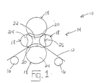
- a papermaking machine 10 for processing a paper web 12 which generally includes an air press assembly 14 and a plurality of conveyor rolls 16.
- Air press assembly 14 is constituted of a plurality of press rolls 18 juxtaposed with one another so as to define a plurality of nips 20 therebetween and an air chamber 22 thereamongst. Contacting a set of end faces 24 of press rolls 18 is an end seal arrangement 26 for closing off what would otherwise be an open end of air chamber 22.
- End seal arrangement 26 is composed of a piston holder 28 (Fig. 2), a seal piston 30, a seal holder 32, at least a first seal member 34 and an adjustable bias mechanism 36.
- Piston holder 28, seal piston 30, seal holder 32 and first seal member 34, by each specifically helping to define the boundary of air chamber 22, are all exposed to the air chamber pressure.
- Piston holder 28 acts as an outer structural member for end seal arrangement 26.
- Piston holder 28 has a holder side wall 38 within which seal piston 30 is movably mounted.
- a gasket 40 is provided in seal piston 30 adjacent holder side wall 38 to ensure sealing contact therebetween.
- Seal piston 30 is movably mounted within piston holder 28 so to facilitate both the positioning of and the adjustment of a biasing force B applied on at least first seal member 34.
- Seal holder 32 extends from seal piston 30 opposite piston holder 28 and holds at least first seal member 34 therein. Seal holder 32 may either be integral with seal piston 30, as shown in Fig. 2, or attached thereto. First seal member 34 is configured for directly contacting and sealing with end faces 24. If only first seal member 34 is employed, first seal member 34 would advantageously made of a hard seal material and would be bonded directly to seal holder 32, in addition to being exposed to air chamber 22.
- first seal member 34 is provided between and bonded to each of first seal member 34 and seal holder 32.
- First and second seal members 34, 42 can be considered roll seals as each seals with end faces 24 of press rolls 18.
- second seal member 42 is advantageously made of a hard seal material
- first seal member 34 is favorably made of a soft seal material.
- the soft seal material deforms to form an efficient seal interface between end seal arrangement 26 and corresponding end faces 24.
- a hard seal material offers increased stiffness and wear resistance in comparison to a soft seal material.
- first and second seal members 34, 42 may advantageously be made of a hard seal material in order to ensure sufficient seal stability and to minimize the rate at which seal wear occurs, as that wear rate is set by the hardest seal material present and in contact with each end face 24.
- First and second seal members 34, 42 may advantageously be made of a carbon fiber (CF) composite and/or polytetrafluoroethylene (PTFE) (commonly known by its trade name "Teflon®”), respectively.
- CF carbon fiber
- PTFE polytetrafluoroethylene
- First seal member 34 and, if present, second seal member 42 are sized and configured to maintain a separation distance 44 between each end face 24 and seal holder 32 to avoid wearing of seal holder 32. As such, the time between seal member changes is dictated by the wear time needed to cause separation distance 44 to reach zero.
- first seal member 34 and second seal member 42 together define a seal boundary 48, seal boundary 48 encompassing a pressurized seal area 50 (schematically shown) therewithin.
- inner holder face 52 of holder side wall 38 bounds and thereby defines a pressurized piston area 54 (schematically shown). Since, in the embodiment shown in Fig. 2, pressurized seal area 50 is approximately equal to pressurized piston area 54, the pressures are balanced throughout seal boundary 48, advantageously resulting in essentially no net chamber seal force F being applied upon first seal member 34 and/or second seal member 42, regardless of the air chamber pressure. Under balanced pressure conditions, chamber seal force F is independent of the air chamber pressure.
- both seal boundary 48 and holder side wall 38 define a similar dog-bone shape (Fig. 1). It is contemplated that those shapes could differ (e.g., seal boundary 48 could define a dog-bone shape and holder side wall 38, a circle) as long as the areas encompassed thereby were essentially the same.
- first seal member 34 and/or second seal member 42 By achieving no net chamber seal force F regardless of air chamber pressure, the risk is avoided of underloading first seal member 34 and/or second seal member 42 in the case of a drop in air chamber pressure and of thus inviting possible leakage and/or slow seal breakage. Likewise, the risk of overloading first seal member 34 and/or second seal member 42 in the case of a rise in air chamber pressure and thus wearing out first seal member 34 and/or second seal member 42 at an even greater rate is also avoided when pressures are balanced. If, for example, pressurized piston area 54 were instead greater than pressurized seal area 50, chamber seal force F would exist on first seal member 34 and/or second seal member 42 due to the air chamber pressure, chamber seal force F increasing with increasing air chamber pressure. In certain instances, it may prove desirable to have pressurized piston area 54 be slightly greater than pressurized seal area 50 so that a small chamber seal force F and, thus, a sealing function would exist in all operational situations.
- Adjustable bias mechanism 36 is configured for controlling a position of first seal member 34 and, if present, second seal member 42 relative to a respective set of end faces 24 and for providing a biasing force B between each of first seal member 34 and second seal member 42, if present, and respective end faces 24. Adjustable bias mechanism 36 is capable of generating the smallest possible biasing force B needed to create a suitable seal between each of first seal member 34 and second seal member 42, if present, and respective end faces 24. It is advantageous to apply the smallest possible biasing force B needed to create a suitable seal as seal wear can be minimized thereby.
- Adjustable bias mechanism 36 is advantageously capable of ensuring that first seal member 34 and second seal member 42, if present, are engaged when air chamber 22 is pressurized; retracting end seal arrangement 26 for startup and maintenance; and regulating biasing force B such that biasing force B is increased during seal break in and decreased once seated to maximize seal life.
- the ability to retract end seal arrangement 26 when nips 20 are being closed avoids the possibility of first seal member 34 and/or second seal member 42 being broken by end faces 24 catching thereon.
- biasing force B is independent of chamber seal force F, even if chamber seal force F is not zero, end seal arrangement 26 can be closed and loaded independently of air chamber pressure. As a result of such independence, such a design can advantageously eliminate the need for springs in the end seal arrangement.
- adjustable bias mechanism 36 includes an air cylinder 56 and an air cylinder shaft 58.
- Air cylinder 56 may either be mounted outside of piston holder 28 (as shown in Fig. 2) or inside thereof (not shown).
- Air cylinder shaft 58 is selectively driven by air cylinder 56 and operably connects air cylinder 56 with seal piston 30. If air cylinder 56 is mounted outside of piston holder 28 with air cylinder shaft 58 accordingly extending therethrough, appropriate seals (not shown) are advantageously provided between air cylinder shaft 58 and piston holder 28 to minimize leakage therebetween.
- end seal arrangement 26 is positioned adjacent a set of end faces 24 of press rolls 18.
- Air cylinder 56 of adjustable biasing mechanism 36 is first used to apply an increased biasing force B during break in of first and second seal members 34, 42.
- Biasing force B is then decreased once seated to a minimum force needed to maintain a sufficient seal between end faces 24 and first and second seal members 34, 42 to maximize seal life thereof.
- End seal arrangement 60 shown in Fig. 3, is a second embodiment of the end seal arrangement of the present invention.
- End seal arrangement 60 is composed of a piston holder 62, a seal piston 64, a seal holder 66, a first seal member 68, a second seal member 70 (optional in the same manner as the first embodiment, requiring first seal member 68 to be bonded directly to seal holder 66 if not used) and an adjustable bias mechanism 72.
- Each end seal arrangement 60 by closing off an open end of air chamber 22, further defines air chamber 22, air chamber 22 having an air chamber pressure associated therewith.
- Piston holder 62, seal piston 64 and o-rings 74 together define adjustable bias mechanism 72.
- Adjustable bias mechanism 72 has an adjustable biasing pressure therein, a net biasing force B1 produced thereby being a function of the difference between the biasing pressure therein and the atmospheric pressure outside of end seal arrangement 60.
- piston holder 62 encompasses a pressurized piston area 76, and the combination of first and second seal members 68, 70 bounds and thereby defines pressurized seal area 78, and pressurized piston area 76 is essentially equal to pressurized seal area 78, thereby producing no net chamber seal force F1.
- first and second seal members 68, 70 are one generated by adjustable bias mechanism 72, i.e., biasing force F1.
- biasing force F1 the biasing pressure in excess of atmospheric produces a positive biasing force B1, resulting in a downward force on first and second seal members 68, 70.
- first and second seal members 68, 70 can be retracted from end faces 24 by applying a less than atmospheric pressure (e.g., a vacuum) within adjustable bias mechanism 72.
- Seal holder 66 is separate from seal piston 64 and is attached thereto via a holder attachment mechanism 80 (e.g., a bolt or screw). Using a separate seal holder 66 eases seal member replacement but introduces the requirement of attaining a sufficient seal between seal holder 66 and seal piston 64.
- a holder attachment mechanism 80 e.g., a bolt or screw
- piston attachment mechanism 82 e.g., a bolt or other attachment pin.
- Piston attachment mechanism 82 extends through seal piston 64 and is mounted in piston holder 62.
- Piston attachment mechanism 82 is supplied with a head 84, head 84 acting as a vertical movement stop for seal piston 64.
- an indicator light 86 (e.g. an LED) is provided on head 84 to act as a visual indicator of a gap and thus a potential leak site between end faces 24 and end seal arrangement 60.
- an indicator light 86 could also be advantageously employed within the first embodiment.
- end seal arrangement 60 Operation of end seal arrangement 60 is similar to that of end seal arrangement 26 with the exception of using a variable biasing pressure within adjustable bias mechanism 72 to produce the desired biasing force B1.
Landscapes
- Paper (AREA)
Applications Claiming Priority (2)
| Application Number | Priority Date | Filing Date | Title |
|---|---|---|---|
| US09/965,611 US6589394B2 (en) | 2001-09-27 | 2001-09-27 | Controlled-force end seal arrangement for an air press of a papermaking machine |
| US965611 | 2001-09-27 |
Publications (2)
| Publication Number | Publication Date |
|---|---|
| EP1298249A2 true EP1298249A2 (fr) | 2003-04-02 |
| EP1298249A3 EP1298249A3 (fr) | 2003-09-03 |
Family
ID=25510219
Family Applications (1)
| Application Number | Title | Priority Date | Filing Date |
|---|---|---|---|
| EP02020898A Withdrawn EP1298249A3 (fr) | 2001-09-27 | 2002-09-18 | Presse à air d'une machine à papier |
Country Status (2)
| Country | Link |
|---|---|
| US (1) | US6589394B2 (fr) |
| EP (1) | EP1298249A3 (fr) |
Cited By (1)
| Publication number | Priority date | Publication date | Assignee | Title |
|---|---|---|---|---|
| EP1335065A3 (fr) * | 2002-02-04 | 2004-05-19 | Voith Paper Patent GmbH | Dispositif d'étanchéité |
Families Citing this family (9)
| Publication number | Priority date | Publication date | Assignee | Title |
|---|---|---|---|---|
| DE10159411A1 (de) * | 2001-12-04 | 2003-06-12 | Voith Paper Patent Gmbh | Vorrichtung zur Entwässerung einer Faserstoffbahn |
| US7494563B2 (en) | 2002-10-07 | 2009-02-24 | Georgia-Pacific Consumer Products Lp | Fabric creped absorbent sheet with variable local basis weight |
| US8673115B2 (en) | 2002-10-07 | 2014-03-18 | Georgia-Pacific Consumer Products Lp | Method of making a fabric-creped absorbent cellulosic sheet |
| US7662257B2 (en) * | 2005-04-21 | 2010-02-16 | Georgia-Pacific Consumer Products Llc | Multi-ply paper towel with absorbent core |
| US8293072B2 (en) | 2009-01-28 | 2012-10-23 | Georgia-Pacific Consumer Products Lp | Belt-creped, variable local basis weight absorbent sheet prepared with perforated polymeric belt |
| US7416637B2 (en) | 2004-07-01 | 2008-08-26 | Georgia-Pacific Consumer Products Lp | Low compaction, pneumatic dewatering process for producing absorbent sheet |
| US7585388B2 (en) * | 2005-06-24 | 2009-09-08 | Georgia-Pacific Consumer Products Lp | Fabric-creped sheet for dispensers |
| US7964105B2 (en) * | 2008-08-07 | 2011-06-21 | William Harris Moss | Method for improving belt press dewatering |
| CA2735867C (fr) | 2008-09-16 | 2017-12-05 | Dixie Consumer Products Llc | Feuille de base d'emballage alimentaire a microfibre de cellulose regeneree |
Family Cites Families (9)
| Publication number | Priority date | Publication date | Assignee | Title |
|---|---|---|---|---|
| US3293121A (en) * | 1963-10-09 | 1966-12-20 | Black Clawson Co | Pneumatically pressurized paper wet press assembly |
| US3315370A (en) * | 1964-05-06 | 1967-04-25 | Hikosaka Hiroshi | Continuous dehydrating apparatus |
| US3808096A (en) * | 1972-02-16 | 1974-04-30 | Beloit Corp | Figure eight cylinder press for defining an extended press nip |
| US3804707A (en) * | 1972-03-08 | 1974-04-16 | Beloit Corp | Papermaking press with inflatable rolls having thin deformable outer shells |
| GB1519265A (en) * | 1975-04-09 | 1978-07-26 | Valmet Oy | Method and apparatus for treatment of a web in order to adjust the moisture content thereof |
| FI772143A7 (fi) * | 1977-07-08 | 1979-01-09 | Tampella Oy Ab | Laongzonspress foer pappersmaskin |
| US4675079A (en) * | 1982-12-14 | 1987-06-23 | Webster David R | Multi-nip suction press with a four roller closed train |
| FI82274C (fi) * | 1989-03-30 | 1991-02-11 | Valmet Paper Machinery Inc | Foerfarande foer varmpressning och torkningsanordning. |
| US6161303A (en) * | 1998-10-29 | 2000-12-19 | Voith Sulzer Papiertechnik Patent Gmbh | Pressing apparatus having chamber end sealing |
-
2001
- 2001-09-27 US US09/965,611 patent/US6589394B2/en not_active Expired - Fee Related
-
2002
- 2002-09-18 EP EP02020898A patent/EP1298249A3/fr not_active Withdrawn
Cited By (1)
| Publication number | Priority date | Publication date | Assignee | Title |
|---|---|---|---|---|
| EP1335065A3 (fr) * | 2002-02-04 | 2004-05-19 | Voith Paper Patent GmbH | Dispositif d'étanchéité |
Also Published As
| Publication number | Publication date |
|---|---|
| US6589394B2 (en) | 2003-07-08 |
| US20030056923A1 (en) | 2003-03-27 |
| EP1298249A3 (fr) | 2003-09-03 |
Similar Documents
| Publication | Publication Date | Title |
|---|---|---|
| US6589394B2 (en) | Controlled-force end seal arrangement for an air press of a papermaking machine | |
| SU1119601A3 (ru) | Способ управлени межвалковым давлением в валковом комплекте со сплошным и составным валками и валок дл его осуществлени | |
| KR100457172B1 (ko) | 제지기계의흡인로울용시일구조 | |
| CA1057986A (fr) | Rouleau a deflexion controlee | |
| JP4757892B2 (ja) | プレス内の板押え力調整システムの改良 | |
| JPH05507130A (ja) | プレスロール | |
| US7527708B2 (en) | Support body, holding device therefor, apparatus with said body for treatment of a web, and methods of forming an extended nip in the apparatus and controlling load in the nip | |
| CA2538046C (fr) | Corps d'appui, dispositif de retenue, appareil equipe du corps d'appui pour le traitement d'une bande continue, procedes de creation d'un espacement allonge dans l'appareil et de regulation de charge dans l'espacement | |
| ATE192800T1 (de) | Schuhpresswalze für eine papiermaschine | |
| CA1288676C (fr) | Dispositif de scellement d'une chambre a contenu sous pression | |
| US6161303A (en) | Pressing apparatus having chamber end sealing | |
| US6306261B1 (en) | Dewatering device and process and glazing device and process | |
| CA2147730A1 (fr) | Cylindre de machine a papier | |
| EP1298247B1 (fr) | Interverrouillage d'étanchéité des rouleaux d'une presse à air d'une machine à papier | |
| EP0373942A2 (fr) | Dispositif de support pour un rouleau cylindrique variable | |
| US20030146581A1 (en) | Sealing arrangement | |
| US4770094A (en) | Control valve for regulating a pressure ratio between two pressure systems | |
| US5900118A (en) | Closed shoe press head indexing system | |
| CA2154377C (fr) | Rouleau a courbure controlee pour calendrier ou dispositif semblable | |
| US20030153443A1 (en) | Elastic roller for a pressing apparatus | |
| KR950701825A (ko) | 만곡형 흡입 박스 장치(a curved suction box apparatus) | |
| US6485612B1 (en) | Air press assembly for use in a paper-making machine | |
| EP0328502A2 (fr) | Procédé pour égaliser le profil de température d'un rouleau à flexion variable et un rouleau pour l'application du procédé | |
| GB2102099A (en) | Improvements in or relating to a roll | |
| AU2002220767A1 (en) | Long nip press for machines transporting fibre webs |
Legal Events
| Date | Code | Title | Description |
|---|---|---|---|
| PUAI | Public reference made under article 153(3) epc to a published international application that has entered the european phase |
Free format text: ORIGINAL CODE: 0009012 |
|
| AK | Designated contracting states |
Kind code of ref document: A2 Designated state(s): AT BE BG CH CY CZ DE DK EE ES FI FR GB GR IE IT LI LU MC NL PT SE SK TR Designated state(s): AT BE BG CH CY CZ DE DK EE ES FI FR GB GR IE IT LI LU MC NL PT SE SK TR |
|
| AX | Request for extension of the european patent |
Extension state: AL LT LV MK RO SI |
|
| PUAL | Search report despatched |
Free format text: ORIGINAL CODE: 0009013 |
|
| AK | Designated contracting states |
Kind code of ref document: A3 Designated state(s): AT BE BG CH CY CZ DE DK EE ES FI FR GB GR IE IT LI LU MC NL PT SE SK TR |
|
| AX | Request for extension of the european patent |
Extension state: AL LT LV MK RO SI |
|
| 17P | Request for examination filed |
Effective date: 20031010 |
|
| AKX | Designation fees paid |
Designated state(s): AT DE FI IT SE |
|
| 17Q | First examination report despatched |
Effective date: 20060727 |
|
| RAP1 | Party data changed (applicant data changed or rights of an application transferred) |
Owner name: VOITH PATENT GMBH |
|
| STAA | Information on the status of an ep patent application or granted ep patent |
Free format text: STATUS: THE APPLICATION IS DEEMED TO BE WITHDRAWN |
|
| 18D | Application deemed to be withdrawn |
Effective date: 20061208 |