EP1298409A1 - Un système de lancement d'une tête de combat avec un dispositif de guidage après tir pour la neutralisation des mines - Google Patents
Un système de lancement d'une tête de combat avec un dispositif de guidage après tir pour la neutralisation des mines Download PDFInfo
- Publication number
- EP1298409A1 EP1298409A1 EP02017902A EP02017902A EP1298409A1 EP 1298409 A1 EP1298409 A1 EP 1298409A1 EP 02017902 A EP02017902 A EP 02017902A EP 02017902 A EP02017902 A EP 02017902A EP 1298409 A1 EP1298409 A1 EP 1298409A1
- Authority
- EP
- European Patent Office
- Prior art keywords
- laser
- warhead
- throwing system
- mine
- mines
- Prior art date
- Legal status (The legal status is an assumption and is not a legal conclusion. Google has not performed a legal analysis and makes no representation as to the accuracy of the status listed.)
- Granted
Links
- 238000006386 neutralization reaction Methods 0.000 title description 12
- 238000012937 correction Methods 0.000 title description 8
- 238000005474 detonation Methods 0.000 claims abstract description 5
- 238000013467 fragmentation Methods 0.000 claims description 20
- 238000006062 fragmentation reaction Methods 0.000 claims description 20
- 206010041662 Splinter Diseases 0.000 claims description 16
- 238000000034 method Methods 0.000 claims description 13
- 238000005286 illumination Methods 0.000 claims description 10
- 230000008569 process Effects 0.000 claims description 7
- 210000003746 feather Anatomy 0.000 claims description 3
- 238000006243 chemical reaction Methods 0.000 claims 1
- 238000006073 displacement reaction Methods 0.000 claims 1
- 239000012634 fragment Substances 0.000 description 6
- 230000007246 mechanism Effects 0.000 description 5
- 230000009471 action Effects 0.000 description 4
- 239000004570 mortar (masonry) Substances 0.000 description 4
- 230000000694 effects Effects 0.000 description 3
- 239000002360 explosive Substances 0.000 description 2
- 238000009434 installation Methods 0.000 description 2
- 230000000149 penetrating effect Effects 0.000 description 2
- 230000035515 penetration Effects 0.000 description 2
- 239000002689 soil Substances 0.000 description 2
- 241001136792 Alle Species 0.000 description 1
- 230000001133 acceleration Effects 0.000 description 1
- 230000000712 assembly Effects 0.000 description 1
- 238000000429 assembly Methods 0.000 description 1
- 230000008901 benefit Effects 0.000 description 1
- 230000005540 biological transmission Effects 0.000 description 1
- 238000005422 blasting Methods 0.000 description 1
- 230000015556 catabolic process Effects 0.000 description 1
- 230000008859 change Effects 0.000 description 1
- 238000010276 construction Methods 0.000 description 1
- 238000001816 cooling Methods 0.000 description 1
- 238000013461 design Methods 0.000 description 1
- 238000011161 development Methods 0.000 description 1
- 230000018109 developmental process Effects 0.000 description 1
- 238000005516 engineering process Methods 0.000 description 1
- 238000011156 evaluation Methods 0.000 description 1
- 239000006260 foam Substances 0.000 description 1
- 229910052734 helium Inorganic materials 0.000 description 1
- 239000001307 helium Substances 0.000 description 1
- SWQJXJOGLNCZEY-UHFFFAOYSA-N helium atom Chemical compound [He] SWQJXJOGLNCZEY-UHFFFAOYSA-N 0.000 description 1
- 230000006872 improvement Effects 0.000 description 1
- 239000007788 liquid Substances 0.000 description 1
- 239000000463 material Substances 0.000 description 1
- 230000003472 neutralizing effect Effects 0.000 description 1
- 230000009291 secondary effect Effects 0.000 description 1
- 230000007723 transport mechanism Effects 0.000 description 1
- 230000001960 triggered effect Effects 0.000 description 1
- 238000009827 uniform distribution Methods 0.000 description 1
- 230000000007 visual effect Effects 0.000 description 1
Images


Classifications
-
- F—MECHANICAL ENGINEERING; LIGHTING; HEATING; WEAPONS; BLASTING
- F41—WEAPONS
- F41H—ARMOUR; ARMOURED TURRETS; ARMOURED OR ARMED VEHICLES; MEANS OF ATTACK OR DEFENCE, e.g. CAMOUFLAGE, IN GENERAL
- F41H11/00—Defence installations; Defence devices
- F41H11/12—Means for clearing land minefields; Systems specially adapted for detection of landmines
-
- F—MECHANICAL ENGINEERING; LIGHTING; HEATING; WEAPONS; BLASTING
- F41—WEAPONS
- F41B—WEAPONS FOR PROJECTING MISSILES WITHOUT USE OF EXPLOSIVE OR COMBUSTIBLE PROPELLANT CHARGE; WEAPONS NOT OTHERWISE PROVIDED FOR
- F41B7/00—Spring guns
-
- F—MECHANICAL ENGINEERING; LIGHTING; HEATING; WEAPONS; BLASTING
- F41—WEAPONS
- F41G—WEAPON SIGHTS; AIMING
- F41G3/00—Aiming or laying means
- F41G3/12—Aiming or laying means with means for compensating for muzzle velocity or powder temperature with means for compensating for gun vibrations
-
- F—MECHANICAL ENGINEERING; LIGHTING; HEATING; WEAPONS; BLASTING
- F41—WEAPONS
- F41G—WEAPON SIGHTS; AIMING
- F41G7/00—Direction control systems for self-propelled missiles
- F41G7/20—Direction control systems for self-propelled missiles based on continuous observation of target position
- F41G7/30—Command link guidance systems
- F41G7/301—Details
-
- F—MECHANICAL ENGINEERING; LIGHTING; HEATING; WEAPONS; BLASTING
- F42—AMMUNITION; BLASTING
- F42B—EXPLOSIVE CHARGES, e.g. FOR BLASTING, FIREWORKS, AMMUNITION
- F42B10/00—Means for influencing, e.g. improving, the aerodynamic properties of projectiles or missiles; Arrangements on projectiles or missiles for stabilising, steering, range-reducing, range-increasing or fall-retarding
- F42B10/60—Steering arrangements
- F42B10/66—Steering by varying intensity or direction of thrust
- F42B10/661—Steering by varying intensity or direction of thrust using several transversally acting rocket motors, each motor containing an individual propellant charge, e.g. solid charge
Definitions
- the invention relates to a system for moving a warhead in a target area as specified in the preamble of claim 1 Features.
- Methods to make the mine so safe to use that it is absorbed and can be blown up in a safe place is to apply it a quick-curing foam to secure the igniter or through Liquid helium cooling to block the trigger mechanism.
- On-board weapons such as machine guns used. These destroy the Mine mechanically or trigger it via the ignition device.
- a mine can be neutralized from a safe distance with fire Damage to the mine will cause an approximation of one Mine clearer no longer allows.
- the fire at hidden mines is basically out of the question. Even if the mine position is visual is marked, the angle of fire from a vehicle is so unfavorable that in many cases the penetration length in the earth area is too long.
- the basic idea of the throwing system according to the invention is one Splinter warhead precisely above the visible mine or - if the mine is below the surface of the earth is not visibly laid - to ignite above its position is either optically marked and / or known as a coordinate.
- the trigger The fragmentation warhead causes every mine to be up to and 30 cm below the surface of the earth is destroyed by the action of fragments.
- the fragment charge contains a fragment density of approximately 0.2 fragments / cm 2 .
- the splinter warhead reaches this splinter density in a circular area of approximately one meter in diameter. To achieve the intended effect, the mine to be destroyed must be within this circle.
- the mortar principle lends itself to degrees.
- the allowable deviation from the target trajectory may - if, for example, a 38 cm mine completely should be hit - not more than 31 cm. This accuracy can cannot be achieved with a mortar with pyrotechnic drive.
- the mechanism of neutralization is based on mine action mechanically by splinters so that they are no longer a danger represent.
- the advantage of this method is that regardless of the Size, design, ignition mechanism and type of installation (on or under surface of the mine) has a high probability of neutralization (also against smart mines).
- the combination of a high-precision mechanical throwing system and one Trajectory correction device ensures that the splinter warhead comes into effect precisely above the mine position and thus a high one Splinter density can be achieved.
- the trajectory correction by microreaction engines is based on one proven technology that enables extremely simple realizations. With only three microreaction engines on the perimeter of the floor can be used once a trajectory correction can be achieved which is the crucial improvement in the accuracy.
- the timing for neutralization is minimal. After recognizing the The mine position is neutralized after approx. 10 seconds.
- the throwing system is excellent for a technical implementation as Suitable kit.
- the modules to be modified change the signature of the Vehicle only insignificantly.
- the throwing system according to the invention enables the implementation of a set-up kit that from the sub-areas of throwing system 20 with straightening device 21, Laser illuminator 7 and fragmentation warhead 3 exists.
- Figures 1 and 2 illustrate the throwing system 20 with the aiming device 21 for the precise movement of the fragmentation warhead 3.
- the straightening device 21 enables the throwing system 20 to be aligned in an azimuth direction 22 in one Range from approx. 0 to 180 degrees and in elevation direction 23 in one area from approx. 60 to 80 degrees.
- a transport position with 0 degrees is provided.
- Throwing system 20 are preferably designed as a feather throwing system significantly lower compared to pyrotechnic transport mechanisms Scattering of the target trajectory allows.
- the principle is to tension springs 1 by means of electric motors 2 so far that when the springs 1 are released the splinter warhead 3 is exactly one selectable starting speed.
- the force / path of the springs 1, which corresponds to this energy, can be used to regulate the clamping process by electric motors 2 precisely via force elements or current sensors 4 in the Power supply of the electric motors 2 are measured. With that, too Influences by temperature and material fatigue in the springs 2 largely be balanced. Since gas-tight guidance of the fragmentation warhead 3 omitted, the fragmentation warhead 3 z. B. in a cup 5 by the Springs 1 is accelerated via a play-free roller guide 6, with less Leaving scatter can be ejected.
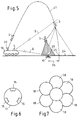
- the laser illuminator 7 shown in FIG. 3 can have two laser beams 8, 9 can be positioned independently of one another in azimuth and elevation, wherein the laser illuminator 7 is positioned on a vehicle 19.
- the first laser beam 8 is used to illuminate a mine 10 or one Surface position under which the mine 10 is located.
- the laser beam 8 can by the vehicle crew via manual aiming at a target recognized mine 10 are performed or automatically via a not closer control unit shown are directed. For this automatic control are then the exact position of the mine and the exact position and direction of the vehicle 19 required.
- the second laser beam 9 has the shape of a fan. Elevation and Azimuth angles are determined with reference to the spatial position of the Illumination laser beam 8 automatically determined.
- the azimuth angle of the The center line of the fan corresponds to the azimuth angle of the illumination laser 8, the elevation angle is larger than the elevation angle by such a value of the illumination laser 8, so that the beam fan 9 in a preselectable Distance 28, which is, for example, 2-4 m above the lighting position 29 of mine 10 runs.
- This laser beam 9 is encoded.
- the fragmentation warhead 3 consists of the following Assemblies: One warhead body 11, one fragmentation charge 12, one on the end of the fragmentation warhead 3 arranged laser position detector 13, the position of the laser light spot 29 of the illumination laser 8 determined, a laser detector 14 with decoding device for detecting the coded laser fan 9, three microreaction engines 15 with ignition device, which are attached to the umfana of the warhead by 120 degrees. and a control and evaluation unit 16, which controls the Laser position detector 13, the laser detector 14, the microreaction engines 15, as well as the ignition of the warhead.
- the throwing system works as follows:
- the electronics and ignition device of the warhead 3 is by the Throwing process activated. Approximately The warhead 3 dives 3 m above the ground 24 through the laser fan 9. This event is detected by the laser detector 14 Decoding device detected. This turns the laser position detector 13 on the front of the warhead 3 turned on, the direction of Impact point 25 to the illumination point 29 of the mine 10. The Direction is determined only as a sector. The number of sectors determines by the number of microreaction engines 15. With three on the circumference 17 equally distributed microreaction engines 15 can be ignited by one or two engines 15 displaced a total of six by 60 degrees each Deflections 18 can be achieved. This is a resolution of the search area in Six directional segments of 60 degrees each are required, depending on the Segment one or two microreaction engines 15 are ignited.
- the laser position detector 13 determines whether the trajectory 27 ends in the spot 29 of the illumination laser 8 or the trajectory 27 has a deposit 26. If a shelf 26 is provided, the angle is measured and the associated one or two engines 15 are ignited. This causes a correction of the trajectory 27 in the direction of the illumination spot 10. Since the height of the laser fan 9 above the surface of the earth and the speed of the warhead are known, the fragmentation warhead 3 can be released about 1 m above the ground after a certain time in which the correction of the trajectory has been completed. The fragments, not shown, are thereby ejected downwards in an approximately uniform distribution at a speed of approx. 800 m / s.
- the release height, the ejection characteristics and the number of splinters are selected so that a splinter density of 0.2 splinters / cm 2 is achieved in a circle of approximately one meter in diameter.
- the kinetic energy of the splinters is sufficient to safely destroy the mines after penetrating 30 cm of soil.
Landscapes
- Engineering & Computer Science (AREA)
- General Engineering & Computer Science (AREA)
- Chemical & Material Sciences (AREA)
- Combustion & Propulsion (AREA)
- Physics & Mathematics (AREA)
- Fluid Mechanics (AREA)
- Aiming, Guidance, Guns With A Light Source, Armor, Camouflage, And Targets (AREA)
- Optical Radar Systems And Details Thereof (AREA)
- Near-Field Transmission Systems (AREA)
- Radar Systems Or Details Thereof (AREA)
- Radio Relay Systems (AREA)
Applications Claiming Priority (2)
| Application Number | Priority Date | Filing Date | Title |
|---|---|---|---|
| DE10147837 | 2001-09-27 | ||
| DE10147837A DE10147837A1 (de) | 2001-09-27 | 2001-09-27 | Wurfsystem für einen Gefechtskopf mit einer Richtvorrichtung zur Neutralisierung von Minen |
Publications (2)
| Publication Number | Publication Date |
|---|---|
| EP1298409A1 true EP1298409A1 (fr) | 2003-04-02 |
| EP1298409B1 EP1298409B1 (fr) | 2006-03-08 |
Family
ID=7700602
Family Applications (1)
| Application Number | Title | Priority Date | Filing Date |
|---|---|---|---|
| EP02017902A Expired - Lifetime EP1298409B1 (fr) | 2001-09-27 | 2002-08-09 | Un système de lancement d'une tête de combat avec un dispositif de guidage après tir pour la neutralisation des mines |
Country Status (6)
| Country | Link |
|---|---|
| US (1) | US6662701B2 (fr) |
| EP (1) | EP1298409B1 (fr) |
| AT (1) | ATE319977T1 (fr) |
| DE (2) | DE10147837A1 (fr) |
| DK (1) | DK1298409T3 (fr) |
| ES (1) | ES2258124T3 (fr) |
Cited By (2)
| Publication number | Priority date | Publication date | Assignee | Title |
|---|---|---|---|---|
| WO2007011398A3 (fr) * | 2004-10-21 | 2007-05-10 | Deka Products Lp | Dispositif de lancement commande |
| CN114877761A (zh) * | 2021-09-26 | 2022-08-09 | 中国人民解放军63921部队 | 一种基于自然岩石环境的深侵惰性弹靶场飞行试验方法 |
Families Citing this family (6)
| Publication number | Priority date | Publication date | Assignee | Title |
|---|---|---|---|---|
| EP1504233A1 (fr) * | 2002-04-12 | 2005-02-09 | Euronord S.A.S. di G.B. Marcolla & C. | Systeme de deminage |
| DE102004046571A1 (de) * | 2004-09-24 | 2006-04-06 | Rheinmetall Landsysteme Gmbh | Vorrichtung zum Verbringen einer Nutzlast, insbesondere zur Neutralisierung von Minen oder dergleichen |
| FR3050814B1 (fr) * | 2016-04-29 | 2019-06-07 | Airbus Helicopters | Procede et dispositif d'aide a la visee pour le guidage laser d'un projectile |
| DE102016113521A1 (de) | 2016-07-21 | 2018-01-25 | Rheinmetall Landsysteme Gmbh | Geschoss |
| US10151555B1 (en) * | 2017-06-08 | 2018-12-11 | Bell Helicopter Textron Inc. | Air cannon with sabot system |
| US10746495B1 (en) * | 2019-08-28 | 2020-08-18 | The United States Of America As Represented By The Secretary Of The Navy | Catapult launcher |
Citations (4)
| Publication number | Priority date | Publication date | Assignee | Title |
|---|---|---|---|---|
| US3860199A (en) * | 1972-01-03 | 1975-01-14 | Ship Systems Inc | Laser-guided projectile system |
| US4176814A (en) * | 1976-04-02 | 1979-12-04 | Ab Bofors | Terminally corrected projectile |
| US4431147A (en) * | 1981-12-24 | 1984-02-14 | The Bendix Corporation | Steerable artillery projectile |
| WO2001016547A2 (fr) * | 1999-07-21 | 2001-03-08 | Primex Technologies, Inc. | Guidage de projectile a reseau en anneau a l'aide d'elements deflecteurs a declenchement optique |
Family Cites Families (31)
| Publication number | Priority date | Publication date | Assignee | Title |
|---|---|---|---|---|
| US3116039A (en) * | 1956-02-29 | 1963-12-31 | Goldberg Michael | Method of and system for guiding a missile |
| US3998406A (en) * | 1964-05-28 | 1976-12-21 | Aeronutronic Ford Corporation | Guided missile system |
| US3743216A (en) * | 1969-01-09 | 1973-07-03 | Us Army | Homing missile system using laser illuminator |
| US4143835A (en) * | 1972-09-12 | 1979-03-13 | The United States Of America As Represented By The Secretary Of The Army | Missile system using laser illuminator |
| US5350134A (en) * | 1973-07-03 | 1994-09-27 | Gec Ferranti Defence Systems Limited | Target identification systems |
| US3924600A (en) * | 1973-07-20 | 1975-12-09 | Geroge C Luebkeman | Throwing arm latch for spring target traps |
| FR2279062A1 (fr) * | 1974-01-02 | 1976-02-13 | Laporte Jean Michel | Appareil de lancement de plateaux pour le tir |
| US3974383A (en) * | 1975-02-03 | 1976-08-10 | Hughes Aircraft Company | Missile tracking and guidance system |
| DE2803036A1 (de) * | 1978-01-25 | 1979-07-26 | Messerschmitt Boelkow Blohm | Gelenkte bombe fuer den tiefflugeinsatz |
| US4300736A (en) * | 1979-08-17 | 1981-11-17 | Raytheon Company | Fire control system |
| DE2947492C2 (de) * | 1979-11-24 | 1983-04-28 | Licentia Patent-Verwaltungs-Gmbh, 6000 Frankfurt | Lenkverfahren für Flugkörper |
| DE2951941C2 (de) * | 1979-12-22 | 1988-01-21 | Diehl GmbH & Co, 8500 Nürnberg | Optische Fernlenkvorrichtung für ein Geschoß |
| CA1180085A (fr) * | 1980-11-21 | 1984-12-27 | Michel M. Fortier | Dispositif d'exercice de bombardement guide par laser |
| US4678143A (en) * | 1982-12-17 | 1987-07-07 | Frazer-Nash Ltd. | Launcher for remotely piloted aircraft |
| US4624424A (en) * | 1984-11-07 | 1986-11-25 | The Boeing Company | On-board flight control drag actuator system |
| DE3441921A1 (de) * | 1984-11-16 | 1986-05-28 | Messerschmitt-Bölkow-Blohm GmbH, 8012 Ottobrunn | Leitstrahl- und nachfuehreinrichtung |
| FR2627268B1 (fr) * | 1988-02-12 | 1993-05-14 | Thomson Brandt Armements | Systeme de guidage de vecteur par faisceau laser et impulseurs pyrotechniques, et vecteur guide par un tel systeme |
| US5102065A (en) * | 1988-02-17 | 1992-04-07 | Thomson - Csf | System to correct the trajectory of a projectile |
| US5011097A (en) * | 1990-08-30 | 1991-04-30 | The United States Of America As Represented By The Secretary Of The Navy | Vehicle steering device |
| DE4035325A1 (de) * | 1990-11-07 | 1992-05-14 | Wegmann & Co | Vorrichtung zur reichweitensteuerung von wurfkoerpern und geschossen, insbesondere in einem wurfsystem fuer nebelkerzen, sprengkoerper u. dgl. |
| FR2669108B1 (fr) * | 1990-11-09 | 1997-01-03 | Thomson Csf | Dispositif optique de mesure de l'angle de roulis d'un projectile. |
| DE4128313C2 (de) * | 1991-08-27 | 2000-04-20 | Diehl Stiftung & Co | Lenk-Flugkörper zur Gefechtskopf-Abwehr |
| DE4325218C2 (de) * | 1993-07-28 | 1998-10-22 | Diehl Stiftung & Co | Artillerie-Rakete und Verfahren zur Leistungssteigerung einer Artillerie-Rakete |
| DE4416211C2 (de) * | 1994-05-07 | 1996-09-26 | Rheinmetall Ind Gmbh | Verfahren und Vorrichtung zur Flugbahnkorrektur von Geschossen |
| DE4425285C2 (de) * | 1994-07-16 | 1997-04-17 | Rheinmetall Ind Ag | Vorrichtung zur Flugbahnkorrektur von drallstabilisierten Geschossen |
| US5458041A (en) * | 1994-08-02 | 1995-10-17 | Northrop Grumman Corporation | Air defense destruction missile weapon system |
| US6062207A (en) * | 1996-05-29 | 2000-05-16 | Underhill; Clinton James | Target trap foot operated cocking and releasing device |
| US5695152A (en) * | 1996-09-18 | 1997-12-09 | Israel Aircraft Industries Ltd. | System for correcting flight trajectory of a projectile |
| US5831724A (en) * | 1997-07-22 | 1998-11-03 | The United States Of America As Represented By The Secretary Of The Navy | Imaging lidar-based aim verification method and system |
| US5988038A (en) * | 1998-01-22 | 1999-11-23 | Raytheon Company | Method and apparatus for destroying buried objects |
| US6422507B1 (en) * | 1999-07-02 | 2002-07-23 | Jay Lipeles | Smart bullet |
-
2001
- 2001-09-27 DE DE10147837A patent/DE10147837A1/de not_active Withdrawn
-
2002
- 2002-08-09 DK DK02017902T patent/DK1298409T3/da active
- 2002-08-09 ES ES02017902T patent/ES2258124T3/es not_active Expired - Lifetime
- 2002-08-09 AT AT02017902T patent/ATE319977T1/de not_active IP Right Cessation
- 2002-08-09 EP EP02017902A patent/EP1298409B1/fr not_active Expired - Lifetime
- 2002-08-09 DE DE50205991T patent/DE50205991D1/de not_active Expired - Lifetime
- 2002-09-25 US US10/253,611 patent/US6662701B2/en not_active Expired - Fee Related
Patent Citations (4)
| Publication number | Priority date | Publication date | Assignee | Title |
|---|---|---|---|---|
| US3860199A (en) * | 1972-01-03 | 1975-01-14 | Ship Systems Inc | Laser-guided projectile system |
| US4176814A (en) * | 1976-04-02 | 1979-12-04 | Ab Bofors | Terminally corrected projectile |
| US4431147A (en) * | 1981-12-24 | 1984-02-14 | The Bendix Corporation | Steerable artillery projectile |
| WO2001016547A2 (fr) * | 1999-07-21 | 2001-03-08 | Primex Technologies, Inc. | Guidage de projectile a reseau en anneau a l'aide d'elements deflecteurs a declenchement optique |
Cited By (4)
| Publication number | Priority date | Publication date | Assignee | Title |
|---|---|---|---|---|
| WO2007011398A3 (fr) * | 2004-10-21 | 2007-05-10 | Deka Products Lp | Dispositif de lancement commande |
| US8061343B2 (en) | 2004-10-21 | 2011-11-22 | Deka Products Limited Partnership | Controllable launcher |
| CN114877761A (zh) * | 2021-09-26 | 2022-08-09 | 中国人民解放军63921部队 | 一种基于自然岩石环境的深侵惰性弹靶场飞行试验方法 |
| CN114877761B (zh) * | 2021-09-26 | 2023-11-07 | 中国人民解放军63921部队 | 一种基于自然岩石环境的深侵惰性弹靶场飞行试验方法 |
Also Published As
| Publication number | Publication date |
|---|---|
| US20030126979A1 (en) | 2003-07-10 |
| DE50205991D1 (de) | 2006-05-04 |
| DE10147837A1 (de) | 2003-04-24 |
| EP1298409B1 (fr) | 2006-03-08 |
| DK1298409T3 (da) | 2006-04-18 |
| ES2258124T3 (es) | 2006-08-16 |
| US6662701B2 (en) | 2003-12-16 |
| ATE319977T1 (de) | 2006-03-15 |
Similar Documents
| Publication | Publication Date | Title |
|---|---|---|
| DE10346001B4 (de) | Vorrichtung zum Schützen von Schiffen vor endphasengelenkten Flugkörpern | |
| DE69900454T2 (de) | Verfahren und vorrichtung zur vernichtung von erdverlegten gegenständen | |
| DE2336040A1 (de) | Abwehrsystem, insbesondere fuer die panzerbekaempfung | |
| EP0971199A1 (fr) | Dispositif pour la destruction de charges militaires | |
| DE102007007403A1 (de) | Verfahren und Vorrichtung zum Schutz gegen fliegende Angriffsmunitionskörper | |
| DE2905422A1 (de) | Einrichtung zur schussimulation mit trefferanzeige | |
| DE69121427T2 (de) | Geschoss und sein Verwendungsverfahren | |
| DE69410376T2 (de) | Waffensystem für die verteidigung eines gebietes | |
| EP1298409B1 (fr) | Un système de lancement d'une tête de combat avec un dispositif de guidage après tir pour la neutralisation des mines | |
| DE3705383C2 (fr) | ||
| DE112012004949T5 (de) | Splitterstrahl-Panzer-Projektil | |
| DE69006564T2 (de) | Automatisches waffensystem für die flächenverteidigung. | |
| DE4029898C2 (fr) | ||
| DE19729483A1 (de) | Verfahren und Vorrichtung zur Beseitigung von Landminen | |
| DE3013405C2 (de) | Verfahren zum Vermeiden des Nachrichtens von Abschußgeräten für ballistische Flugkörper | |
| DE3123339A1 (de) | Verfahren zur fernzuendung eines sprenggeschosses, insbesondere eines hubschrauberabwehrgeschosses sowie einrichtung und geschoss zur durchfuehrung des verfahrens | |
| WO1986006470A1 (fr) | Procede pour declencher une fusee detonatrice de proximite et dispositif pour l'execution du procede | |
| EP0708305B1 (fr) | Procédé pour protéger des objets rayonnants contre des missiles, en particulier des objets émettant un rayonnement dans l'infrarouge comme des navires | |
| EP3943874A1 (fr) | Dispositif de luttes contre une cible | |
| DE3543769A1 (de) | Mine zur abwehr von bewegten objekten | |
| DE3326748C2 (fr) | ||
| DE19617060C2 (de) | Verfahren und Einrichtung zur Simulation der Wirkung von Steilfeuerwaffen auf Gefechtseinheiten | |
| DE3904293A1 (de) | Flaechenwaffe | |
| DE2922592A1 (de) | Verfahren zur abwehr von flugkoerpern | |
| DE102015000871A1 (de) | Minenräumgerät und Verfahren zum Räumen von Minen |
Legal Events
| Date | Code | Title | Description |
|---|---|---|---|
| PUAI | Public reference made under article 153(3) epc to a published international application that has entered the european phase |
Free format text: ORIGINAL CODE: 0009012 |
|
| 17P | Request for examination filed |
Effective date: 20021219 |
|
| AK | Designated contracting states |
Kind code of ref document: A1 Designated state(s): AT BE BG CH CY CZ DE DK EE ES FI FR GB GR IE IT LI LU MC NL PT SE SK TR Designated state(s): AT BE BG CH CY CZ DE DK EE ES FI FR GB GR IE IT LI LU MC NL PT SE SK TR |
|
| AX | Request for extension of the european patent |
Extension state: AL LT LV MK RO SI |
|
| AKX | Designation fees paid |
Designated state(s): AT BE BG CH CY CZ DE DK EE ES FI FR GB GR IE IT LI LU MC NL PT SE SK TR |
|
| GRAP | Despatch of communication of intention to grant a patent |
Free format text: ORIGINAL CODE: EPIDOSNIGR1 |
|
| RAP1 | Party data changed (applicant data changed or rights of an application transferred) |
Owner name: RHEINMETALL LANDSYSTEME GMBH |
|
| GRAS | Grant fee paid |
Free format text: ORIGINAL CODE: EPIDOSNIGR3 |
|
| GRAA | (expected) grant |
Free format text: ORIGINAL CODE: 0009210 |
|
| AK | Designated contracting states |
Kind code of ref document: B1 Designated state(s): AT BE BG CH CY CZ DE DK EE ES FI FR GB GR IE IT LI LU MC NL PT SE SK TR |
|
| PG25 | Lapsed in a contracting state [announced via postgrant information from national office to epo] |
Ref country code: SK Free format text: LAPSE BECAUSE OF FAILURE TO SUBMIT A TRANSLATION OF THE DESCRIPTION OR TO PAY THE FEE WITHIN THE PRESCRIBED TIME-LIMIT Effective date: 20060308 Ref country code: IE Free format text: LAPSE BECAUSE OF FAILURE TO SUBMIT A TRANSLATION OF THE DESCRIPTION OR TO PAY THE FEE WITHIN THE PRESCRIBED TIME-LIMIT Effective date: 20060308 Ref country code: FI Free format text: LAPSE BECAUSE OF FAILURE TO SUBMIT A TRANSLATION OF THE DESCRIPTION OR TO PAY THE FEE WITHIN THE PRESCRIBED TIME-LIMIT Effective date: 20060308 |
|
| REG | Reference to a national code |
Ref country code: GB Ref legal event code: FG4D Free format text: NOT ENGLISH |
|
| REG | Reference to a national code |
Ref country code: CH Ref legal event code: EP |
|
| GBT | Gb: translation of ep patent filed (gb section 77(6)(a)/1977) |
Effective date: 20060308 |
|
| REG | Reference to a national code |
Ref country code: IE Ref legal event code: FG4D Free format text: LANGUAGE OF EP DOCUMENT: GERMAN |
|
| REG | Reference to a national code |
Ref country code: DK Ref legal event code: T3 |
|
| REF | Corresponds to: |
Ref document number: 50205991 Country of ref document: DE Date of ref document: 20060504 Kind code of ref document: P |
|
| REG | Reference to a national code |
Ref country code: SE Ref legal event code: TRGR |
|
| PG25 | Lapsed in a contracting state [announced via postgrant information from national office to epo] |
Ref country code: BG Free format text: LAPSE BECAUSE OF FAILURE TO SUBMIT A TRANSLATION OF THE DESCRIPTION OR TO PAY THE FEE WITHIN THE PRESCRIBED TIME-LIMIT Effective date: 20060608 |
|
| PG25 | Lapsed in a contracting state [announced via postgrant information from national office to epo] |
Ref country code: PT Free format text: LAPSE BECAUSE OF FAILURE TO SUBMIT A TRANSLATION OF THE DESCRIPTION OR TO PAY THE FEE WITHIN THE PRESCRIBED TIME-LIMIT Effective date: 20060808 |
|
| PGFP | Annual fee paid to national office [announced via postgrant information from national office to epo] |
Ref country code: DK Payment date: 20060815 Year of fee payment: 5 |
|
| REG | Reference to a national code |
Ref country code: ES Ref legal event code: FG2A Ref document number: 2258124 Country of ref document: ES Kind code of ref document: T3 |
|
| PG25 | Lapsed in a contracting state [announced via postgrant information from national office to epo] |
Ref country code: MC Free format text: LAPSE BECAUSE OF NON-PAYMENT OF DUE FEES Effective date: 20060831 Ref country code: LI Free format text: LAPSE BECAUSE OF NON-PAYMENT OF DUE FEES Effective date: 20060831 Ref country code: CH Free format text: LAPSE BECAUSE OF NON-PAYMENT OF DUE FEES Effective date: 20060831 |
|
| ET | Fr: translation filed | ||
| PGFP | Annual fee paid to national office [announced via postgrant information from national office to epo] |
Ref country code: BE Payment date: 20060914 Year of fee payment: 5 |
|
| REG | Reference to a national code |
Ref country code: IE Ref legal event code: FD4D |
|
| PLBE | No opposition filed within time limit |
Free format text: ORIGINAL CODE: 0009261 |
|
| STAA | Information on the status of an ep patent application or granted ep patent |
Free format text: STATUS: NO OPPOSITION FILED WITHIN TIME LIMIT |
|
| 26N | No opposition filed |
Effective date: 20061211 |
|
| REG | Reference to a national code |
Ref country code: CH Ref legal event code: PL |
|
| PG25 | Lapsed in a contracting state [announced via postgrant information from national office to epo] |
Ref country code: AT Free format text: LAPSE BECAUSE OF NON-PAYMENT OF DUE FEES Effective date: 20060809 |
|
| BERE | Be: lapsed |
Owner name: *RHEINMETALL LANDSYSTEME G.M.B.H. Effective date: 20070831 |
|
| REG | Reference to a national code |
Ref country code: DK Ref legal event code: EBP |
|
| PG25 | Lapsed in a contracting state [announced via postgrant information from national office to epo] |
Ref country code: GR Free format text: LAPSE BECAUSE OF FAILURE TO SUBMIT A TRANSLATION OF THE DESCRIPTION OR TO PAY THE FEE WITHIN THE PRESCRIBED TIME-LIMIT Effective date: 20060609 Ref country code: CZ Free format text: LAPSE BECAUSE OF FAILURE TO SUBMIT A TRANSLATION OF THE DESCRIPTION OR TO PAY THE FEE WITHIN THE PRESCRIBED TIME-LIMIT Effective date: 20060308 |
|
| PG25 | Lapsed in a contracting state [announced via postgrant information from national office to epo] |
Ref country code: EE Free format text: LAPSE BECAUSE OF FAILURE TO SUBMIT A TRANSLATION OF THE DESCRIPTION OR TO PAY THE FEE WITHIN THE PRESCRIBED TIME-LIMIT Effective date: 20060308 |
|
| PG25 | Lapsed in a contracting state [announced via postgrant information from national office to epo] |
Ref country code: TR Free format text: LAPSE BECAUSE OF FAILURE TO SUBMIT A TRANSLATION OF THE DESCRIPTION OR TO PAY THE FEE WITHIN THE PRESCRIBED TIME-LIMIT Effective date: 20060308 Ref country code: LU Free format text: LAPSE BECAUSE OF NON-PAYMENT OF DUE FEES Effective date: 20060809 Ref country code: DK Free format text: LAPSE BECAUSE OF NON-PAYMENT OF DUE FEES Effective date: 20070831 |
|
| PG25 | Lapsed in a contracting state [announced via postgrant information from national office to epo] |
Ref country code: BE Free format text: LAPSE BECAUSE OF NON-PAYMENT OF DUE FEES Effective date: 20070831 |
|
| REG | Reference to a national code |
Ref country code: ES Ref legal event code: FD2A Effective date: 20070810 |
|
| PG25 | Lapsed in a contracting state [announced via postgrant information from national office to epo] |
Ref country code: CY Free format text: LAPSE BECAUSE OF FAILURE TO SUBMIT A TRANSLATION OF THE DESCRIPTION OR TO PAY THE FEE WITHIN THE PRESCRIBED TIME-LIMIT Effective date: 20060308 |
|
| PG25 | Lapsed in a contracting state [announced via postgrant information from national office to epo] |
Ref country code: ES Free format text: LAPSE BECAUSE OF NON-PAYMENT OF DUE FEES Effective date: 20070810 |
|
| PGFP | Annual fee paid to national office [announced via postgrant information from national office to epo] |
Ref country code: SE Payment date: 20090813 Year of fee payment: 8 Ref country code: NL Payment date: 20090814 Year of fee payment: 8 Ref country code: GB Payment date: 20090827 Year of fee payment: 8 Ref country code: DE Payment date: 20090821 Year of fee payment: 8 |
|
| PGFP | Annual fee paid to national office [announced via postgrant information from national office to epo] |
Ref country code: IT Payment date: 20090819 Year of fee payment: 8 |
|
| REG | Reference to a national code |
Ref country code: NL Ref legal event code: V1 Effective date: 20110301 |
|
| EUG | Se: european patent has lapsed | ||
| GBPC | Gb: european patent ceased through non-payment of renewal fee |
Effective date: 20100809 |
|
| REG | Reference to a national code |
Ref country code: FR Ref legal event code: ST Effective date: 20110502 |
|
| PG25 | Lapsed in a contracting state [announced via postgrant information from national office to epo] |
Ref country code: NL Free format text: LAPSE BECAUSE OF NON-PAYMENT OF DUE FEES Effective date: 20110301 Ref country code: IT Free format text: LAPSE BECAUSE OF NON-PAYMENT OF DUE FEES Effective date: 20100809 |
|
| REG | Reference to a national code |
Ref country code: DE Ref legal event code: R119 Ref document number: 50205991 Country of ref document: DE Effective date: 20110301 |
|
| PG25 | Lapsed in a contracting state [announced via postgrant information from national office to epo] |
Ref country code: DE Free format text: LAPSE BECAUSE OF NON-PAYMENT OF DUE FEES Effective date: 20110301 Ref country code: FR Free format text: LAPSE BECAUSE OF NON-PAYMENT OF DUE FEES Effective date: 20100831 |
|
| PG25 | Lapsed in a contracting state [announced via postgrant information from national office to epo] |
Ref country code: GB Free format text: LAPSE BECAUSE OF NON-PAYMENT OF DUE FEES Effective date: 20100809 |
|
| PGFP | Annual fee paid to national office [announced via postgrant information from national office to epo] |
Ref country code: FR Payment date: 20090914 Year of fee payment: 8 |
|
| PG25 | Lapsed in a contracting state [announced via postgrant information from national office to epo] |
Ref country code: SE Free format text: LAPSE BECAUSE OF NON-PAYMENT OF DUE FEES Effective date: 20100810 |