EP1299194B1 - Pistolet pulverisateur - Google Patents
Pistolet pulverisateur Download PDFInfo
- Publication number
- EP1299194B1 EP1299194B1 EP01962787A EP01962787A EP1299194B1 EP 1299194 B1 EP1299194 B1 EP 1299194B1 EP 01962787 A EP01962787 A EP 01962787A EP 01962787 A EP01962787 A EP 01962787A EP 1299194 B1 EP1299194 B1 EP 1299194B1
- Authority
- EP
- European Patent Office
- Prior art keywords
- pressure
- spray gun
- gun body
- compressed air
- gun
- Prior art date
- Legal status (The legal status is an assumption and is not a legal conclusion. Google has not performed a legal analysis and makes no representation as to the accuracy of the status listed.)
- Expired - Lifetime
Links
Images




Classifications
-
- B—PERFORMING OPERATIONS; TRANSPORTING
- B05—SPRAYING OR ATOMISING IN GENERAL; APPLYING FLUENT MATERIALS TO SURFACES, IN GENERAL
- B05B—SPRAYING APPARATUS; ATOMISING APPARATUS; NOZZLES
- B05B12/00—Arrangements for controlling delivery; Arrangements for controlling the spray area
- B05B12/004—Arrangements for controlling delivery; Arrangements for controlling the spray area comprising sensors for monitoring the delivery, e.g. by displaying the sensed value or generating an alarm
- B05B12/006—Pressure or flow rate sensors
- B05B12/008—Pressure or flow rate sensors integrated in or attached to a discharge apparatus, e.g. a spray gun
-
- B—PERFORMING OPERATIONS; TRANSPORTING
- B05—SPRAYING OR ATOMISING IN GENERAL; APPLYING FLUENT MATERIALS TO SURFACES, IN GENERAL
- B05B—SPRAYING APPARATUS; ATOMISING APPARATUS; NOZZLES
- B05B7/00—Spraying apparatus for discharge of liquids or other fluent materials from two or more sources, e.g. of liquid and air, of powder and gas
- B05B7/24—Spraying apparatus for discharge of liquids or other fluent materials from two or more sources, e.g. of liquid and air, of powder and gas with means, e.g. a container, for supplying liquid or other fluent material to a discharge device
- B05B7/2402—Apparatus to be carried on or by a person, e.g. by hand; Apparatus comprising containers fixed to the discharge device
- B05B7/2478—Gun with a container which, in normal use, is located above the gun
-
- Y—GENERAL TAGGING OF NEW TECHNOLOGICAL DEVELOPMENTS; GENERAL TAGGING OF CROSS-SECTIONAL TECHNOLOGIES SPANNING OVER SEVERAL SECTIONS OF THE IPC; TECHNICAL SUBJECTS COVERED BY FORMER USPC CROSS-REFERENCE ART COLLECTIONS [XRACs] AND DIGESTS
- Y10—TECHNICAL SUBJECTS COVERED BY FORMER USPC
- Y10S—TECHNICAL SUBJECTS COVERED BY FORMER USPC CROSS-REFERENCE ART COLLECTIONS [XRACs] AND DIGESTS
- Y10S239/00—Fluid sprinkling, spraying, and diffusing
- Y10S239/14—Paint sprayers
Definitions
- the invention relates to a spray gun according to the preamble of claim 1.
- a spray gun is made US 5 191 797 A known.
- an injection pressure may e.g. to color changes in the basecoat, to an increase in the orange peel structure in the clear coat and varnish and to reduce the operating speed and possibly the beam width.
- too low an injection pressure may e.g. to color changes in the basecoat, to an increase in the orange peel structure in the clear coat and varnish and to reduce the operating speed and possibly the beam width.
- too high an injection pressure can lead to excessive atomization of the spray material and thus lead to greater losses and undesirable stress on the working environment.
- the available pressure should be monitored, e.g. to detect a possible pressure drop due to additional consumers in the compressed air line network or a pressure increase due to the addition of resources.
- a pressure control valve with pressure gauge On the pressure gauge can be read via a knob on the pressure control valve adjustable pressure.
- this arranged at the air inlet of the paint spray gun pressure control valve with pressure gauge leads to an extension of the spray gun, whereby their handiness is deteriorated.
- the pressure gauge or the pressure regulating valve due to the inner deflections leads to a pressure drop.
- the usually screwed pressure control valve must be dismantled for cleaning the spray gun in washing or cleaning basins, since the accuracy of the manometer can be affected by penetrating solvent or paint or paint residues.
- the pressure control valve with the pressure gauge must therefore be unscrewed during each cleaning process, which is associated with a considerable amount of work.
- paint spray guns which have at the handle bottom a connection for coupling a conventional manometer.
- the pressure gauges commonly used have as a pressure transducer usually a semicircular or helically bent steel tube spring, whose conditional by the pressure change in shape is indicated by a pointer on a corresponding dial.
- the steel tube spring and the display device are housed in a separate housing.
- the handling of the spray gun is affected by the coupled manometer.
- the manometers must also be removable for cleaning the paint spray gun, so that relatively complicated coupling or connection systems for the connection of the manometer to the spray gun are required.
- the pressure measuring device is installed in a separate closed housing, which is used with all the components arranged therein in a provided on the top of the gun body receiving bore.
- This housing includes an opening communicating with a compressed air passage downstream of the air valve. In this arrangement, however, only the gun internal pressure after the valve assembly and not the gun input pressure can be determined.
- a pressure measuring device in which a capillary tube is provided between a pressure sensor and a connector.
- the capillary tube is intended to prevent rapid pressure changes or pressure surges from acting on the pressure sensor abruptly, thereby falsifying the measurement result.
- the object of the invention is to provide a handy spray gun that allows detection of the gun input pressure and is protected against contamination of the sensitive pressure measuring device.
- the gun body includes a provided in his handle pressure sensing space for the pressure transducer.
- a capillary is provided between the compressed air supply passage and the pressure sensing space, the capillary being disposed in a communication passage between the pressure sensing space and a portion of the compressed air supply passage located upstream of the valve assembly.
- the display device and a possible circuit arrangement for signal conversion and evaluation e.g. integrated into the handle of the spray gun.
- the entire measuring device is housed within the gun body and there optimally protected against damage.
- the display device which can be embodied as an analogue or digital display can be arranged on a rear end part of the gun body in such a way that the display field can be read from the rear. This results in the advantage that the pressure indication during spraying is always in the field of vision.
- the spray gun shown in Fig. 1 includes a gun body 1 with a handle 2 and an upper part 3, on which a suspension hook 4 is formed. Through the upper part 3 extends from the front to the rear continuous and multi-stepped through hole 5, in which a nozzle needle 6 is guided axially displaceable.
- the through hole 5 forms in a front region an enlarged receiving space 7, in which an oblique inlet bore 8 opens to the attachment of a color receiving container, not shown.
- a nozzle assembly 9 is mounted, which contains a fixable by means of a thread on the upper part 3 of the gun body 1 paint nozzle 10.
- the paint nozzle 10 has at its front end a nozzle bore 11 which, together with a tapered front end portion of an actuating lever 12 axially movable nozzle needle 6 an adjustable inlet for the paint, the paint or the like.
- the actuating lever 12 is connected to the nozzle needle 6 in such a way that, upon retraction of the actuating lever 12, it is displaced against the force of a spring 13 towards the rear and opens the nozzle bore 11 for dispensing the ink.
- the bias of the compression spring 13 and the stroke of the nozzle needle 6 are adjustable.
- the actuating lever 12 is also a recognizable in Fig. 4 valve assembly 17 with a rear adjusting device 18 for controlling the compressed air supply to the nozzle assembly 9 via a rod 16 operable.
- the nozzle assembly 9 and its structure is already known as such.
- a possible nozzle arrangement is eg in the EP 0710 506 A1 disclosed.
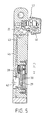
- the spray gun includes an integrated into the handle 2 of the gun body 1 pressure measuring device 27, which consists essentially of a pressure transducer 28, a circuit arrangement 29 and a display device 30.
- the e.g. designed as a piezoelectric pressure sensor pressure sensor 28 is inserted into a laterally provided in the handle 2 blind hole 31, which defines a pressure sensing space 33 with an upper measuring surface 32.
- the pressure transducer 28 is connected via electrical connections 34 to the circuit arrangement 29, which consists essentially of a arranged in a corresponding receiving space 35 in the pistol grip 2 board with the corresponding circuit.
- the circuit 29 is the e.g. arranged as LCD display display device 30 for the display of the detected by the pressure transducer 28 pressure.
- the circuit arrangement 29 and the display device 30 are held in the pistol grip 2 via an intermediate element 36 by a cover plate 38 provided with a viewing window 37.
- the final with the side surface of the pistol grip 2 cover plate 38 is sealed to prevent fluid and dirt entry by sealing elements 39 screwed to the pistol grip 2.
- On the side opposite to the display device 30 side of the handle 2 a closable by a cover 40 receiving compartment 41 is provided for a battery 42 for the electrical supply of the evaluation circuit and display device.
- the pressure sensing space 33 is connected by a connecting channel 44 provided with a capillary 43 to the upstream portion of the valve assembly 19 of the compressed air supply passage in the area of the gun inlet.
- the capillary is designed as a bore with a diameter of 0.5 to 1.8 mm.
- the connecting channel 44 is in the form of a means of a ball 45 closed to the outside lateral connecting hole.
- Solvent and possibly dissolved paint particles get into the pressure detection chamber and there lead to an impairment of the accuracy or even prevent a measurement.
- FIGS. 4 to 6 differs from the embodiment described above in that the capillary 43 is arranged in a connecting channel 46 which lies between the pressure-sensing chamber 33 and a part 20 of the compressed-air supply channel arranged downstream of the valve arrangement 17 , Thereby, the set by the adjusting device 18 and available for spraying air pressure can be detected and displayed.
- a further adjusting device 47 is shown with a lateral knob 48 for regulating the supply of compressed air to the bores 23.
- the further construction of the spray gun corresponds to the embodiment shown in FIGS. 1 to 3.
- the pressure sensor 28 is arranged in a separate receiving chamber 49 above the circuit arrangement 29, the display device 30 and the receiving compartment 41 for the battery 42. Otherwise, the spray gun is essentially constructed as in the previously described embodiment according to FIGS. 4 to 6. Also in this embodiment, the adjusted by the actuator 18 working pressure can be detected and displayed.
- FIGS. 10 and 11 show a further embodiment of a spray gun.
- the gun body 1 has a rear end piece 50 which is either integral with the. Upper part 3 or as e.g. can be executed screwed or plug-in end part.
- a receiving chamber 51 is provided with a pressure-sensing space 52 for the pressure transducer 28.
- the pressure detection room. 52 is connected via a arranged in the axial direction of the end capillary 53 to the compressed air supply channel upstream of the valve assembly 17.
- a digital display device 54 is arranged with a display panel 55 such that it is visible from behind when working with the spray gun. The pressure can thus be constantly monitored during spraying.
- the invention is not limited to the embodiments described above and shown in the drawing.
- piezoelectric pressure transducer instead of piezoelectric pressure transducer Other suitable pressure transducers or pressure sensors are used.
- the pressure transducers can also be attached to other suitable locations of the PistoIen stressess.
Landscapes
- Chemical & Material Sciences (AREA)
- Analytical Chemistry (AREA)
- Physics & Mathematics (AREA)
- Fluid Mechanics (AREA)
- Nozzles (AREA)
- Spray Control Apparatus (AREA)
Claims (4)
- Pistolet pulvérisateur avec- un corps de pistolet (1),- un ensemble de buse (9) disposé dans le corps de pistolet (1),- un canal (19, 20) d'apport d'air comprimé disposé dans le corps de pistolet (1) et pourvu d'un ensemble de soupape (17) pour commander l'apport d'air comprimé à l'ensemble de buse (9),- un équipement de réglage (6, 13) pour régler l'apport de produit à projeter,- un élément d'actionnement (12) pour actionner l'ensemble de soupape (17) et l'équipement de réglage (6, 13), et- un équipement (27) de mesure de pression intégré dans le corps de pistolet, avec un capteur de pression (28) et un équipement d'affichage (30) pour détecter et afficher la pression dans le canal (19, 20) d'apport d'air comprimé,caractérisé en ce que le corps de pistolet (1) contient une chambre (33) de détection de pression, prévue dans sa poignée (2), pour le capteur de pression (28), et en ce qu'un tube capillaire (43) est disposé entre le canal (19, 20) d'apport d'air comprimé et la chambre (33) de détection de pression pour empêcher la pénétration dans la chambre (33) de détection de pression d'un produit de nettoyage ou dissolvant utilisé pour nettoyer le pistolet pulvérisateur, sachant que le tube capillaire (43) est disposé à l'intérieur du corps de pistolet (1) dans un canal de liaison (44) entre la chambre (33) de détection de pression et une partie (19) du canal (19, 20) d'apport d'air comprimé qui est située en amont de l'ensemble de soupape (17).
- Pistolet pulvérisateur selon la revendication 1, caractérisé en ce que l'équipement d'affichage (30) est incorporé dans la poignée (2) du corps de pistolet (1).
- Pistolet pulvérisateur selon la revendication 1 ou 2, caractérisé en ce que l'équipement (27) de mesure de pression contient un montage électrique (29) disposé dans le corps de pistolet (1).
- Pistolet pulvérisateur selon l'une des revendications 1 à 3, caractérisé en ce qu'une chambre réceptrice (41) pour une batterie (42) est disposée dans le corps de pistolet (1).
Applications Claiming Priority (3)
| Application Number | Priority Date | Filing Date | Title |
|---|---|---|---|
| DE10031857A DE10031857A1 (de) | 2000-06-30 | 2000-06-30 | Spritzpistole |
| DE10031857 | 2000-06-30 | ||
| PCT/EP2001/007324 WO2002002242A1 (fr) | 2000-06-30 | 2001-06-27 | Pistolet pulverisateur |
Publications (2)
| Publication Number | Publication Date |
|---|---|
| EP1299194A1 EP1299194A1 (fr) | 2003-04-09 |
| EP1299194B1 true EP1299194B1 (fr) | 2007-10-31 |
Family
ID=7647326
Family Applications (1)
| Application Number | Title | Priority Date | Filing Date |
|---|---|---|---|
| EP01962787A Expired - Lifetime EP1299194B1 (fr) | 2000-06-30 | 2001-06-27 | Pistolet pulverisateur |
Country Status (5)
| Country | Link |
|---|---|
| US (1) | US7017838B2 (fr) |
| EP (1) | EP1299194B1 (fr) |
| JP (1) | JP3968123B2 (fr) |
| DE (2) | DE10031857A1 (fr) |
| WO (1) | WO2002002242A1 (fr) |
Cited By (7)
| Publication number | Priority date | Publication date | Assignee | Title |
|---|---|---|---|---|
| US9327301B2 (en) | 2008-03-12 | 2016-05-03 | Jeffrey D. Fox | Disposable spray gun cartridge |
| US9333519B2 (en) | 2010-12-02 | 2016-05-10 | Sata Gmbh & Co. Kg | Spray gun and accessories |
| US9409197B2 (en) | 2013-12-18 | 2016-08-09 | Sata Gmbh & Co. Kg | Air nozzle closure for a spray gun |
| USD768820S1 (en) | 2014-09-03 | 2016-10-11 | Sata Gmbh & Co. Kg | Paint spray gun with pattern |
| USD770593S1 (en) | 2014-07-31 | 2016-11-01 | Sata Gmbh & Co. Kg | Paint spray gun |
| US9533317B2 (en) | 2009-07-08 | 2017-01-03 | Sata Gmbh & Co. Kg | Paint spray gun |
| DE202019103497U1 (de) * | 2019-06-25 | 2020-10-06 | Sata Gmbh & Co. Kg | Spritzpistole, insbesondere Farbspritzpistole |
Families Citing this family (48)
| Publication number | Priority date | Publication date | Assignee | Title |
|---|---|---|---|---|
| JP3533387B2 (ja) * | 2002-01-18 | 2004-05-31 | アネスト岩田株式会社 | 圧力表示スプレーガン |
| GB2389908B (en) | 2002-06-18 | 2005-05-18 | Itw Ltd | Pressure gauge |
| USD552715S1 (en) * | 2005-07-28 | 2007-10-09 | Sata Gmbh & Co. Kg | Paint spray gun |
| US20070262169A1 (en) * | 2006-05-01 | 2007-11-15 | Chia Chung Precision Industrial Co., Ltd. | Spray head structure of a spray gun |
| US7568874B2 (en) * | 2006-06-02 | 2009-08-04 | Pur Water Purification Products, Inc. | Nut for attaching two devices and method for providing the same |
| USD582763S1 (en) | 2006-06-02 | 2008-12-16 | Pur Water Purification Products, Inc. | Threaded nut |
| USD629487S1 (en) | 2008-04-17 | 2010-12-21 | The Procter & Gamble Company | Connector for a faucet mounted water filter |
| USD629865S1 (en) | 2008-04-17 | 2010-12-28 | The Procter & Gambple Company | Connector for a faucet mounted water filter |
| USD568149S1 (en) * | 2007-07-23 | 2008-05-06 | Pur Water Purification Products, Inc. | Threaded nut |
| USD573227S1 (en) * | 2006-06-12 | 2008-07-15 | Titan Tool, Inc. | Texture spray gun |
| DE502007000825D1 (de) | 2006-12-05 | 2009-07-16 | Sata Gmbh & Co Kg | Belüftung für den Fließbecher einer Farbspritzpistole |
| MX2010002610A (es) | 2007-09-05 | 2010-03-30 | Pur Water Purification Prod | Aparato y metodos para sistemas de filtracion de agua para grifo. |
| US8584973B2 (en) * | 2007-10-31 | 2013-11-19 | Nordson Corporation | Powder coating gun with manually operated controls on gun |
| CN101909766A (zh) | 2008-01-09 | 2010-12-08 | 阿克佐诺贝尔国际涂料股份有限公司 | 涂漆装置 |
| US7793549B1 (en) * | 2008-10-14 | 2010-09-14 | Chien-Chih Yeh | Pressure gauge locking structure of paintball gun |
| DE202008014389U1 (de) | 2008-10-29 | 2010-04-08 | Sata Gmbh & Co. Kg | Fließbecher für eine Farbspritzpistole |
| DE202010007355U1 (de) | 2010-05-28 | 2011-10-20 | Sata Gmbh & Co. Kg | Düsenkopf für eine Spritzvorrichtung |
| TWD145058S (zh) * | 2010-08-12 | 2012-02-01 | 薩塔有限兩合公司 | 噴漆槍(二) |
| USD637690S1 (en) | 2010-08-18 | 2011-05-10 | The Procter & Gamble Company | Connector for a faucet mounted water filter |
| USD637693S1 (en) | 2010-08-18 | 2011-05-10 | The Procter & Gamble Company | Connector for a faucet mounted water filter |
| USD637691S1 (en) | 2010-08-18 | 2011-05-10 | The Procter & Gamble Company | Connector for a faucet mounted water filter |
| CN107537707B (zh) | 2011-06-30 | 2021-09-03 | 萨塔有限两合公司 | 喷枪、喷射介质引导单元、盖子、底座本体及相关方法 |
| US20130075489A1 (en) * | 2011-09-27 | 2013-03-28 | Shiqi Zhu | Pneumatic spray gun with digital pressure readout |
| USD689593S1 (en) | 2012-01-27 | 2013-09-10 | Sata Gmbh & Co. Kg | Spray gun |
| RU2482927C2 (ru) * | 2012-03-12 | 2013-05-27 | Анистрад Григорьевич Васильев | Распылитель жидкости |
| USD690799S1 (en) * | 2012-07-02 | 2013-10-01 | Sata Gmbh & Co. Kg | Spray gun with pattern |
| DE202012104781U1 (de) | 2012-12-10 | 2013-01-30 | Sata Gmbh & Co. Kg | Spritzpistole und Druckmesseinrichtung für eine Spritzpistole |
| CA155474S (en) | 2013-09-27 | 2015-08-27 | Sata Gmbh & Co Kg | Spray gun |
| CN105289870B (zh) | 2014-07-31 | 2019-09-24 | 萨塔有限两合公司 | 喷枪的制造方法、喷枪、喷枪本体以及盖 |
| USD758537S1 (en) | 2014-07-31 | 2016-06-07 | Sata Gmbh & Co. Kg | Paint spray gun rear portion |
| JP1535002S (fr) | 2015-03-17 | 2015-10-13 | ||
| DE102015006484A1 (de) | 2015-05-22 | 2016-11-24 | Sata Gmbh & Co. Kg | Düsenanordnung für eine Spritzpistole, insbesondere Farbspritzpistole und Spritzpistole, insbesondere Farbspritzpistole |
| DE102015016474A1 (de) | 2015-12-21 | 2017-06-22 | Sata Gmbh & Co. Kg | Luftkappe und Düsenanordnung für eine Spritzpistole und Spritzpistole |
| FR3047074B1 (fr) * | 2016-01-21 | 2018-01-26 | Pfeiffer Vacuum | Dispositif d'aspersion et module de detection de fuites |
| CN205995666U (zh) | 2016-08-19 | 2017-03-08 | 萨塔有限两合公司 | 喷枪及其扳机 |
| CN205966208U (zh) | 2016-08-19 | 2017-02-22 | 萨塔有限两合公司 | 风帽组件以及喷枪 |
| USD863016S1 (en) | 2017-09-19 | 2019-10-15 | Campbell Hausfeld, Llc | Inflation gun |
| EP3517213B1 (fr) | 2018-01-26 | 2022-12-14 | Graco Minnesota Inc. | Pistolet de pulvérisation de texture portable avec trémie |
| DE102018118737A1 (de) | 2018-08-01 | 2020-02-06 | Sata Gmbh & Co. Kg | Düse für eine Spritzpistole, Düsensatz für eine Spritzpistole, Spritzpistolen und Verfahren zur Herstellung einer Düse für eine Spritzpistole |
| CN112533705B (zh) | 2018-08-01 | 2023-07-04 | 萨塔有限两合公司 | 喷枪的喷嘴组、喷枪系统、制造喷嘴模块的方法、为上漆任务从喷嘴组选出喷嘴模块的方法、选择系统和计算机程序产品 |
| DE102018118738A1 (de) | 2018-08-01 | 2020-02-06 | Sata Gmbh & Co. Kg | Grundkörper für eine Spritzpistole, Spritzpistolen, Spritzpistolen-Set, Verfahren zur Herstellung eines Grundkörpers für eine Spritzpistole und Verfahren zum Umrüsten einer Spritzpistole |
| DE102018122004A1 (de) | 2018-09-10 | 2020-03-12 | Sata Gmbh & Co. Kg | Lackierpistole, Materialauftragssystem und Verfahren zu dessen Betrieb |
| DE102020106172A1 (de) | 2020-03-06 | 2021-09-09 | Sata Gmbh & Co. Kg | Spritzpistole, insbesondere druckluftzerstäubende Farbspritzpistole, insbesondere handgeführte druckluftzerstäubende Farbspritzpistole |
| DE102020106171A1 (de) | 2020-03-06 | 2021-09-09 | Sata Gmbh & Co. Kg | Spritzpistole, insbesondere Farbspritzpistole |
| DE102020123769A1 (de) | 2020-09-11 | 2022-03-17 | Sata Gmbh & Co. Kg | Dichtelement zum Abdichten eines Übergangs zwischen einem Grundkörper einer Spritzpistole und einem Anbauteil einer Spritzpistole, Anbauteil, insbesondere Farbdüsenanordnung, für eine Spritzpistole und Spritzpistole, insbesondere Farbspritzpistole |
| JP7905351B2 (ja) * | 2021-10-05 | 2026-08-14 | 株式会社コガネイ | エアブローガン |
| USD1046076S1 (en) | 2021-10-15 | 2024-10-08 | Sata Gmbh & Co. Kg | Spray gun |
| CN114534946A (zh) * | 2022-02-14 | 2022-05-27 | 深圳市洲明科技股份有限公司 | 一种显示屏加工工艺及加工设备 |
Family Cites Families (12)
| Publication number | Priority date | Publication date | Assignee | Title |
|---|---|---|---|---|
| US3482781A (en) * | 1968-03-18 | 1969-12-09 | Sharpe Mfg Co | Spray gun with pressure gauge feature |
| JPS5654328A (en) | 1979-10-11 | 1981-05-14 | Shinagawa Sokki Seisakusho:Kk | Manufacture of pressure gauge |
| DE3313249A1 (de) * | 1983-04-13 | 1984-10-25 | Woma-Apparatebau Wolfgang Maasberg & Co Gmbh, 4100 Duisburg | Hochdruckwasserstrahl-anlage |
| GB9009190D0 (en) * | 1990-04-24 | 1990-06-20 | Devilbiss The Company Limited | Miniature electronic pressure gauge |
| JP3031435B2 (ja) * | 1991-08-20 | 2000-04-10 | 旭サナック株式会社 | 自動塗装における塗料吐出量制御方法 |
| US5191757A (en) * | 1991-11-18 | 1993-03-09 | Case Corporation | Discharge conveying system for a cotton harvester |
| JPH0674850A (ja) * | 1992-08-28 | 1994-03-18 | Ishikawajima Harima Heavy Ind Co Ltd | 密閉容器の圧力計測方法及びその装置 |
| DE59403043D1 (de) | 1994-10-05 | 1997-07-10 | Sata Farbspritztechnik | Düsenanordnung für eine Farbspritzpistole |
| DE19535010C2 (de) * | 1995-09-21 | 1998-01-22 | Pelikan Produktions Ag | Verwendung eines Tropfenerzeugers in einem medizinischen Gerät zum dosierten Zuführen eines Medikamentes zu einem Fluidstrom |
| JPH09155253A (ja) * | 1995-12-07 | 1997-06-17 | Alloy Koki Kk | 液体噴射ガンにおけるスピット発生防止装置 |
| US5979797A (en) * | 1998-08-14 | 1999-11-09 | Castellano; Michael A. | Handheld pressurized hopper gun and method |
| DE10135104C1 (de) * | 2001-07-19 | 2002-09-12 | Sata Farbspritztechnik | Farbspritzpistole |
-
2000
- 2000-06-30 DE DE10031857A patent/DE10031857A1/de not_active Withdrawn
-
2001
- 2001-06-27 EP EP01962787A patent/EP1299194B1/fr not_active Expired - Lifetime
- 2001-06-27 JP JP2002506860A patent/JP3968123B2/ja not_active Expired - Lifetime
- 2001-06-27 WO PCT/EP2001/007324 patent/WO2002002242A1/fr not_active Ceased
- 2001-06-27 US US10/312,278 patent/US7017838B2/en not_active Expired - Lifetime
- 2001-06-27 DE DE50113197T patent/DE50113197D1/de not_active Expired - Lifetime
Cited By (8)
| Publication number | Priority date | Publication date | Assignee | Title |
|---|---|---|---|---|
| US9327301B2 (en) | 2008-03-12 | 2016-05-03 | Jeffrey D. Fox | Disposable spray gun cartridge |
| US9533317B2 (en) | 2009-07-08 | 2017-01-03 | Sata Gmbh & Co. Kg | Paint spray gun |
| US9333519B2 (en) | 2010-12-02 | 2016-05-10 | Sata Gmbh & Co. Kg | Spray gun and accessories |
| US9409197B2 (en) | 2013-12-18 | 2016-08-09 | Sata Gmbh & Co. Kg | Air nozzle closure for a spray gun |
| USD770593S1 (en) | 2014-07-31 | 2016-11-01 | Sata Gmbh & Co. Kg | Paint spray gun |
| USD798419S1 (en) | 2014-07-31 | 2017-09-26 | Sata Gmbh & Co. Kg | Paint spray gun |
| USD768820S1 (en) | 2014-09-03 | 2016-10-11 | Sata Gmbh & Co. Kg | Paint spray gun with pattern |
| DE202019103497U1 (de) * | 2019-06-25 | 2020-10-06 | Sata Gmbh & Co. Kg | Spritzpistole, insbesondere Farbspritzpistole |
Also Published As
| Publication number | Publication date |
|---|---|
| DE10031857A1 (de) | 2002-01-17 |
| US20030189105A1 (en) | 2003-10-09 |
| DE50113197D1 (de) | 2007-12-13 |
| WO2002002242A1 (fr) | 2002-01-10 |
| JP3968123B2 (ja) | 2007-08-29 |
| JP2004501763A (ja) | 2004-01-22 |
| EP1299194A1 (fr) | 2003-04-09 |
| US7017838B2 (en) | 2006-03-28 |
Similar Documents
| Publication | Publication Date | Title |
|---|---|---|
| EP1294490B1 (fr) | Pistolet-pulverisateur | |
| WO2002002242A1 (fr) | Pistolet pulverisateur | |
| EP1277519B1 (fr) | Pistolet a peinture avec indicateur de pression | |
| EP2427275B1 (fr) | Pistolet a pulverisation comprenant un dispositif de mesure de la pression amovible | |
| EP0438065B1 (fr) | Assemblage de soupape fileté, notamment pour une soupape d'étranglement | |
| DE3928733C2 (de) | Manometer mit schraubenförmig aufgewickelten Bourdonrohrspulen | |
| DE20011469U1 (de) | Spritzpistole | |
| DE102020133986A1 (de) | Digitaldruckmesseinheit zum Messen und Anzeigen eines Luft- und/oder Materialdrucks, vorzugsweise einer Lackierpistole, sowie Lackierpistole mit einer Digitaldruckmesseinheit | |
| EP1573277B1 (fr) | Element de raccordement pour conduites fluidiques | |
| DE20011470U1 (de) | Spritzpistole | |
| DE3730940A1 (de) | Vorrichtung zur anzeige der stellung des kolbens eines ventils | |
| DE102005060674C5 (de) | Positionssensor in Stabbauweise sowie Verfahren zum Austausch | |
| EP1464842B1 (fr) | Dispositif pour l'obtention d'un vide | |
| DE10131644A1 (de) | Flüssigkeitsabgabeeinrichtung für ein Hochdruckreinigungsgerät | |
| WO2019096566A1 (fr) | Système de filtre | |
| DE20314362U1 (de) | Nietverarbeitungsgerät | |
| DE20111954U1 (de) | Farbspritzpistole | |
| EP0671599A2 (fr) | Appareil de mesure pneumatique pour contrôler des dimensions d'un objet | |
| DE29823702U1 (de) | Strömungswächter | |
| DE10156929B4 (de) | Volumenstrommesser und Gaszähler mit Entspannungskammer | |
| DE202009006562U1 (de) | Spritzpistole mit Druckmesseinrichtung | |
| DE20122100U1 (de) | Flüssigkeitsabgabeeinrichtung für ein Hochdruckreinigungsgerät | |
| DE10100065B4 (de) | Verfahren, Computerprogramm und Vorrichtung zum Messen der Einspritzmenge von Einspritzsystemen, insbesondere für Kraftfahrzeuge | |
| DE3732922C2 (fr) | ||
| EP0494253A1 (fr) | Appareil de nettoyage haute-pression. |
Legal Events
| Date | Code | Title | Description |
|---|---|---|---|
| PUAI | Public reference made under article 153(3) epc to a published international application that has entered the european phase |
Free format text: ORIGINAL CODE: 0009012 |
|
| 17P | Request for examination filed |
Effective date: 20030130 |
|
| AK | Designated contracting states |
Kind code of ref document: A1 Designated state(s): AT BE CH CY DE DK ES FI FR GB GR IE IT LI LU MC NL PT SE TR |
|
| RBV | Designated contracting states (corrected) |
Designated state(s): DE FR GB IT |
|
| RAP1 | Party data changed (applicant data changed or rights of an application transferred) |
Owner name: SATA GMBH & CO. KG |
|
| GRAP | Despatch of communication of intention to grant a patent |
Free format text: ORIGINAL CODE: EPIDOSNIGR1 |
|
| GRAS | Grant fee paid |
Free format text: ORIGINAL CODE: EPIDOSNIGR3 |
|
| GRAA | (expected) grant |
Free format text: ORIGINAL CODE: 0009210 |
|
| AK | Designated contracting states |
Kind code of ref document: B1 Designated state(s): DE FR GB IT |
|
| REG | Reference to a national code |
Ref country code: GB Ref legal event code: FG4D Free format text: NOT ENGLISH |
|
| REF | Corresponds to: |
Ref document number: 50113197 Country of ref document: DE Date of ref document: 20071213 Kind code of ref document: P |
|
| GBT | Gb: translation of ep patent filed (gb section 77(6)(a)/1977) |
Effective date: 20071206 |
|
| ET | Fr: translation filed | ||
| PLBE | No opposition filed within time limit |
Free format text: ORIGINAL CODE: 0009261 |
|
| STAA | Information on the status of an ep patent application or granted ep patent |
Free format text: STATUS: NO OPPOSITION FILED WITHIN TIME LIMIT |
|
| 26N | No opposition filed |
Effective date: 20080801 |
|
| REG | Reference to a national code |
Ref country code: FR Ref legal event code: PLFP Year of fee payment: 16 |
|
| REG | Reference to a national code |
Ref country code: FR Ref legal event code: PLFP Year of fee payment: 17 |
|
| REG | Reference to a national code |
Ref country code: FR Ref legal event code: PLFP Year of fee payment: 18 |
|
| PGFP | Annual fee paid to national office [announced via postgrant information from national office to epo] |
Ref country code: FR Payment date: 20200623 Year of fee payment: 20 Ref country code: DE Payment date: 20200623 Year of fee payment: 20 |
|
| PGFP | Annual fee paid to national office [announced via postgrant information from national office to epo] |
Ref country code: GB Payment date: 20200625 Year of fee payment: 20 |
|
| PGFP | Annual fee paid to national office [announced via postgrant information from national office to epo] |
Ref country code: IT Payment date: 20200630 Year of fee payment: 20 |
|
| REG | Reference to a national code |
Ref country code: DE Ref legal event code: R071 Ref document number: 50113197 Country of ref document: DE |
|
| REG | Reference to a national code |
Ref country code: GB Ref legal event code: PE20 Expiry date: 20210626 |
|
| PG25 | Lapsed in a contracting state [announced via postgrant information from national office to epo] |
Ref country code: GB Free format text: LAPSE BECAUSE OF EXPIRATION OF PROTECTION Effective date: 20210626 |