EP1300284A2 - Dispositif de verrouillage pour conteneur - Google Patents
Dispositif de verrouillage pour conteneur Download PDFInfo
- Publication number
- EP1300284A2 EP1300284A2 EP02021414A EP02021414A EP1300284A2 EP 1300284 A2 EP1300284 A2 EP 1300284A2 EP 02021414 A EP02021414 A EP 02021414A EP 02021414 A EP02021414 A EP 02021414A EP 1300284 A2 EP1300284 A2 EP 1300284A2
- Authority
- EP
- European Patent Office
- Prior art keywords
- locking
- locking unit
- arrangement
- arrangement according
- carrier
- Prior art date
- Legal status (The legal status is an assumption and is not a legal conclusion. Google has not performed a legal analysis and makes no representation as to the accuracy of the status listed.)
- Granted
Links
Images



Classifications
-
- B—PERFORMING OPERATIONS; TRANSPORTING
- B60—VEHICLES IN GENERAL
- B60P—VEHICLES ADAPTED FOR LOAD TRANSPORTATION OR TO TRANSPORT, TO CARRY, OR TO COMPRISE SPECIAL LOADS OR OBJECTS
- B60P1/00—Vehicles predominantly for transporting loads and modified to facilitate loading, consolidating the load, or unloading
- B60P1/64—Vehicles predominantly for transporting loads and modified to facilitate loading, consolidating the load, or unloading the load supporting or containing element being readily removable
- B60P1/6418—Vehicles predominantly for transporting loads and modified to facilitate loading, consolidating the load, or unloading the load supporting or containing element being readily removable the load-transporting element being a container or similar
- B60P1/6481—Specially adapted for carrying different numbers of container or containers of different sizes
-
- B—PERFORMING OPERATIONS; TRANSPORTING
- B60—VEHICLES IN GENERAL
- B60P—VEHICLES ADAPTED FOR LOAD TRANSPORTATION OR TO TRANSPORT, TO CARRY, OR TO COMPRISE SPECIAL LOADS OR OBJECTS
- B60P7/00—Securing or covering of load on vehicles
- B60P7/06—Securing of load
- B60P7/13—Securing freight containers or forwarding containers on vehicles
-
- B—PERFORMING OPERATIONS; TRANSPORTING
- B60—VEHICLES IN GENERAL
- B60P—VEHICLES ADAPTED FOR LOAD TRANSPORTATION OR TO TRANSPORT, TO CARRY, OR TO COMPRISE SPECIAL LOADS OR OBJECTS
- B60P7/00—Securing or covering of load on vehicles
- B60P7/06—Securing of load
- B60P7/13—Securing freight containers or forwarding containers on vehicles
- B60P7/132—Securing freight containers or forwarding containers on vehicles twist-locks for containers or frames
Definitions
- the invention relates to a locking arrangement for holding containers on a chassis.
- Chassis for holding exchangeable containers can be used with one Step frame can be designed as a so-called Gooseneck chassis and thereby using high cube (HC) containers within the framework of the given regulations Pick up the Gooseneck tunnel in the container floor.
- HC high cube
- step frames it is also possible to transport containers with a flat floor surface different designs of locking arrangements attached to the chassis, from below using a lockable pivot in fittings of the container, known.
- EP 0 337 011 A1 shows a carrying device which is one horizontal axis is pivotally mounted on the chassis and two locking devices has different distances from the pivot axis have and can optionally be pivoted into the carrying position.
- DE 296 16 083 U1 has a height-adjustable locking device described for swap bodies, in which a first locking housing is firmly connected to a support for a deeper support and a second locking housing for the deeper support next to the side the first locking housing and by pivoting about a joint can be placed on the first housing to provide higher support to build.
- a locking arrangement is known from DE 195 38 915 A1, in which a vertical prismatic guide is firmly connected to a chassis is. In the guide, a slide can be moved vertically and in two different ways Height positions can be locked. The slider is laterally offset a lock housing attached with a pivot lock, which is height adjustable with the slider. A similar locking arrangement is known from DE 296 22 249 U1.
- DE 197 55 638 C2 shows a locking arrangement, in which a further development DE 195 38 915 A1 the locking housing itself within the vertical guide lies and can be fixed in two height positions.
- DE 19 66 501 A1 describes a device for locking transport containers described on vehicles in which a locking insert between an upper working position and a lower retracted position is movable. There is a protrusion on a vertical plate of the insert formed, which engages in a recess of a rear wall plate and supports the insert vertically. A releasable locking member holds the projection in the Recess. A second working position is not planned.
- the present invention has for its object a simple structure and manageable, inexpensive locking arrangement for mounting of containers in two different height positions.
- the locking arrangement according to the invention enables in particular in the upper position the stable vertical support of the locking unit in one Support bearing arrangement by pivoting the locking unit around a horizontal axis or by displacement with a horizontal movement component, preferably by a combination of both forms of movement can be moved from the upper stop position without a vertically supporting additional element such as a plug pin or a Intermediate pipe section must be relocated.
- the vertical support can therefore very stable and structurally simple and takes up little space be and the handling is particularly easy.
- Under the pivot vertical direction is a pivoting movement with predominantly vertical pivot movement component of a spaced from the pivot axis Support of the locking unit.
- that forms Swivel bearing itself a second support.
- the two spaced supports advantageously close the support surface in the horizontal direction of a container to be held.
- a combination of a pivoting movement and one is particularly advantageous Movement with a horizontal movement component of the locking unit.
- the locking unit in at least the upper, preferably also the lower holding position through coordinated design of the locking unit, Carrier arrangement and, if necessary, connecting guide elements against it translational displacement is form-fitting, and that this is fixing only by pivoting the locking unit around a horizontal one Axis through a minimum angle of e.g. > 45 ° can be canceled.
- the locking unit e.g. in the typical Execution as a pivot lock already by engaging in the Container fitting against swiveling on the horizontal swivel axis is locked, the locking unit is when the container is attached and locked also safe against high vertical and horizontal forces the carrier assembly held.
- the pivoting of the locking unit around a horizontal axis can advantageously be used according to a development of the invention the locking unit is lower than the lower holding position
- To shift parking position which is preferably a swivel a stop position is made by more than 180 °.
- the carrier arrangement has two parallel vertical plates, which the locking unit enclose between themselves and in each of which a backdrop is formed, in which a connected to the locking unit Set element is guided.
- the backdrop element can preferably also be used as Swivel shaft for pivoting the locking device by one serve horizontal axis.
- the backdrop element can e.g. a preferred be releasably connected to the locking unit bolt, rod, etc.
- the Guidance in the link arrangement can be advantageous in the way with the pivoting be combined that endpoints and / or reversal points one Set the slide at the same time as pivot bearings for the pivoting.
- the locking unit can advantageously be guided through the link arrangement at the same time as protection against loss and / or quick theft serve the locking unit.
- the one delimited by the two vertical, preferably parallel plates Space is advantageously in the direction facing away from the cross member largely open, which in particular allows easy access to the locking unit for their adjustment and / or for actuating the lock and during the displacement of the locking unit between the holding positions or possibly a parking position a movement of the locking device beyond the plate edges is possible.
- the locking device is advantageously a pivot lock, especially designed with a twistable pivot.
- the locking unit can in both stop positions and possibly the parking position by one or several securing elements secured in their position relative to the carrier arrangement his.
- the securing elements are preferably under spring tension held in their securing position and, for example, as on the carrier assembly attached spring bolt with a in a counter opening of the locking unit engaging locking bolt.
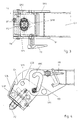
- FIGS. 1 to 7 instructs QT on a cross member whose end facing away from the central longitudinal axis of a chassis is a carrier arrangement which consists essentially of two vertical support plates TP1, TP2 exists, which e.g. to the vertical side surfaces of the as a rectangular profile trained cross member and welded to the cross member are.
- the type of attachment of the support plates to the cross member is not of further importance below.
- the two support plates run flat and parallel to each other and delimit in the direction of travel FA, i.e. a receiving space in the longitudinal direction of the chassis, within which a locking unit has different positions can take.
- Shaped backdrop tracks are in the support plates TP1, TP2 KB formed in which a guide bolt running in the direction of travel FB is performed as a backdrop element.
- the support plates have horizontal top edges POK on.
- One of the support plates preferably the support plate lying in the direction of travel TP1 carries a spring bolt FR with a safety bolt, which depends on Position of the locking unit in one of several safety openings intervenes.
- the locking unit consists of a Locking housing, which has a lockable locking pin contains.
- the locking pin protrudes with one at the top of one Locking bolt RB located, flattened mushroom-shaped head PZ on both sides beyond the upper contact surface AF of the locking housing and engages when placing a container in a downward opening of a Container corner fitting EB.
- Using a KN knob at the lower end of the locking bolt RB the entire pin can be turned through 90 ° and locks the corner fitting.
- Using a clamping nut SPM on a thread the locking pin can be pulled down and the container fitting can be clamped against the locking housing.
- a locking latch RF prevents the clamping nut from being unintentionally loosened SPM.
- the locking principle described by means of a braced vertical locking pin is known and in use.
- the locking housing comprises essentially two parallel vertical side plates SP1, SP2, one horizontal upper support plate AP, a side support plate STP and a lower counter plate, on which the clamping nut is supported.
- the side plates SP1, SP2 run parallel to the support plates TP1, TP2 within the confined space and limited to the side Distance from these.
- the lower counter plate UP again runs between the two side plates SP1, SP2.
- the support plate AP and the support plate STP are preferably made in one piece as an angled plate. Platen with support plate, side plates and counter plate are advantageous welded together to form the locking housing of the locking unit.
- the guide pin FB is passed through holes in the side plates SP1, SP2 and secured in the longitudinal direction against displacement, for example by inserting the guide pin into one between the side plates and preferably runs with this welded bearing tube LR and by means of a securing element which extends through the bearing tube and guide pin is secured against displacement in the longitudinal direction.
- the securing element e.g. a screw SCH, is preferably only used of a tool releasable, so that the securing bolt in the longitudinal direction and then the locking unit can be removed from the receiving space are unauthorized theft but through the necessary use of tools is difficult.
- Other security options for such Guide bolts are known in various designs.
- the locking housing is around the longitudinal axis of the guide pin FB this can be pivoted and with the guide pin along the slide track displaceable.
- the guide pin also serves as a one-sided support of the Locking housing against the support plates, at least in the sketched in Fig. 1 upper stop position where the bolt at an upper end KBO the Slide track is inserted and a weight load on the locking housing on one side transfers to the support plates.
- the guide pin FB is vertical Projection outwards against the locking pin.
- the locking case is further in the upper holding position of the guide pin with respect to the locking pin opposite through the support plate STP supported, which stands on the cross member QT.
- the cross member profile is towards the receiving space between the support plates closed by an angle plate LW.
- the side plates SP1, SP2 of the locking housing lie with a counter edge GK of the angle plate LP in their upper area slightly spaced from each other, the shape of the counter edges a horizontal or oblique displacement of the locking housing prevent from the sketched end position of the guide pin, however, a pivoting of the locking housing about the longitudinal axis the guide pin counterclockwise after loosening the spring bolt FR allow.
- the locking housing In the position of the guide pin at the lower end KBU of the slide track the locking housing is swiveled clockwise back into the in Fig. 5 and Fig. 6 outlined lower holding position, the opposite edges of the Side plates SP1, SP2 a short distance from the lower edge of the angle plate LW face and thereby a horizontal displacement of the Prevent the locking housing from moving towards the median longitudinal plane of the vehicle.
- a horizontal shift in the opposite direction is here as well in the upper holding position by inserting the guide pin in the end the backdrop track prevented.
- a vertical displacement of the locking housing without Swiveling is due to the at least approximately horizontal course of the Slide track prevented in the area of its lower end. A swivel is not possible if the locking pin is tensioned.
- the support plate STP dips when the locking unit is moved and swiveled in the lower holding position between the support plates TP1, TP2 on.
- a support for the locking housing against vertical loads in the position outlined in FIGS. 5 and 6 preferably takes the form that the upper platen AP directly on the horizontal upper plate edges POK of the support plates TP1, TP2 rests.
- Locking arrangement can be provided, the locking unit from the swiveled-out position sketched in FIG. 4, not clockwise into a holding position but counterclockwise further into one in Fig. 7 outlined parking position and e.g. by another spring bolt Secure FR2 in this.
- the protrusion of the locking pin over the upper edges of the Carrier plates and the locking arrangement can also be shorter for support Containers used at intermediate positions in the longitudinal direction of the driving position and when transporting longer containers with deep container bottoms be folded away.
- a backdrop track KB8 is outlined, in which the section to the upper end KBO8 of the slide is essentially horizontal. hereby can be a clearer definition of the locking case against lifting acting forces can be achieved.
- the in the example according to Fig. 1 to Fig. 7 selected guide with one to the upper end KBO the backdrop in the last section, the advantage of that with the typical loading of the assembly with the weight of the container the guide pin also in the horizontal direction in a clearly stable End position is pressed.
- the locking housing has two Guide bolts FB1, FB2 are guided in parallel in a link KB9, whereby again the shift between an upper and a lower stop position (the lower stop position is shown) comprises a horizontal path component.
- the insertion of a horizontal path component when moving between an upper and a lower stop position generally allows how
- the examples outlined illustrate that vertical support the guide pin or another bearing element in the upper holding position despite the exactly vertical position of this bearing element in the lower holding position stationary in the carrier arrangement and thus can be simple and stable.
- the setting arrangement offers with the uncomplicated guidance of the locking unit with the shift, the simple safeguard against losing or stealing, the defined end positions, the feasibility as a detail in a flat plate and at the same time low consumption Plate area and thus little impairment of the load-bearing capacity of the support plates special advantages.
- the locking unit is used for the shift between the top and the lower holding position preferably away from the cross member QT 9, for which purpose the slide track between the end positions in the example according to FIG. 9 is offset from the cross member.
- the locking unit by pivoting shifted to the outside.
- the end positions of the backdrop tracks are here compared to the rest of the course tracks outside, so that on the one hand a wide base of support between the guide pin and the support plate section is given in the upper holding position and secondly the lateral one Extension of the support plates can be kept low.
- FIG. 10 shows a further variant, in which a modification of the designs 1 to 8, the bolt ends of the guide bolt on one side are flattened and only form semicircular rod sections FBH and the end positions quarter-round recesses adapted to the KBH slide form in which the bolt ends against linear displacements are secured in all directions.
- a release from this secured position is done by pivoting the locking unit connected to the bolt around the bolt longitudinal axis, whereupon the bolt ends in a vertical Link section between the end positions are displaceable and by swiveling the locking unit back into the end positions.
- there is no horizontal motion component of the whole Bolts when moving between the end positions but instead just a swivel and a vertical shift.
- the vertical The course of the backdrop track is again of secondary importance.
- a Securing the position with flattened bolt ends is also possible for other slide tracks conceivable.
Landscapes
- Engineering & Computer Science (AREA)
- Transportation (AREA)
- Mechanical Engineering (AREA)
- Packages (AREA)
- Clamps And Clips (AREA)
- Handcart (AREA)
- Connection Of Plates (AREA)
- Supplying Of Containers To The Packaging Station (AREA)
- Details Of Rigid Or Semi-Rigid Containers (AREA)
- Fittings On The Vehicle Exterior For Carrying Loads, And Devices For Holding Or Mounting Articles (AREA)
- Passenger Equipment (AREA)
- Body Structure For Vehicles (AREA)
Priority Applications (1)
| Application Number | Priority Date | Filing Date | Title |
|---|---|---|---|
| DE10312595A DE10312595B4 (de) | 2001-10-02 | 2003-03-21 | Verriegelungsanordnung zur Halterung von Containern auf einem Fahrgestell und Fahrgestell mit solchen Verriegelungsanordnungen |
Applications Claiming Priority (2)
| Application Number | Priority Date | Filing Date | Title |
|---|---|---|---|
| DE10148728A DE10148728C1 (de) | 2001-10-02 | 2001-10-02 | Verriegelungsanordnung für Container |
| DE10148728 | 2001-10-02 |
Publications (3)
| Publication Number | Publication Date |
|---|---|
| EP1300284A2 true EP1300284A2 (fr) | 2003-04-09 |
| EP1300284A3 EP1300284A3 (fr) | 2006-06-21 |
| EP1300284B1 EP1300284B1 (fr) | 2007-10-24 |
Family
ID=7701209
Family Applications (1)
| Application Number | Title | Priority Date | Filing Date |
|---|---|---|---|
| EP02021414A Expired - Lifetime EP1300284B1 (fr) | 2001-10-02 | 2002-09-25 | Dispositif de verrouillage pour conteneur |
Country Status (4)
| Country | Link |
|---|---|
| EP (1) | EP1300284B1 (fr) |
| AT (1) | ATE376503T1 (fr) |
| DE (4) | DE10148728C1 (fr) |
| ES (1) | ES2292669T3 (fr) |
Cited By (2)
| Publication number | Priority date | Publication date | Assignee | Title |
|---|---|---|---|---|
| EP1621399A1 (fr) * | 2004-07-28 | 2006-02-01 | Holger Stuht | Dispositif pour verrouiller des conteneurs sur un chassis de véhicule à differentes hauteurs |
| EP3222464A1 (fr) * | 2016-03-24 | 2017-09-27 | Sonntag transport technology GmbH & Co. KG | Système de cadre pour carrosseries de véhicules automobiles |
Families Citing this family (7)
| Publication number | Priority date | Publication date | Assignee | Title |
|---|---|---|---|---|
| DE102004033886B4 (de) * | 2004-07-13 | 2009-04-09 | Schneider Fahrzeug- Und Containertechnik Gmbh | Halteanordnung für Container |
| RU178819U9 (ru) * | 2017-08-29 | 2020-03-03 | РЕЙЛ 1520 АйПи ЛТД | Устройство для крепления контейнеров |
| RU2764316C1 (ru) * | 2021-07-14 | 2022-01-17 | Общество с ограниченной ответственностью "СотекКомЦентр", ООО "СКЦ" | Устройство для крепления контейнеров на платформе |
| RU2763618C1 (ru) * | 2021-07-16 | 2021-12-30 | Общество с ограниченной ответственностью "СотекКомЦентр", ООО "СКЦ" | Устройство для крепления контейнеров на платформе |
| RU209816U1 (ru) * | 2021-12-02 | 2022-03-23 | Общество С Ограниченной Ответственностью "Рейл1520 Ай Пи" (Ооо "Рейл1520 Ай Пи") | Устройство для крепления грузов на транспортном средстве |
| DE102022105423A1 (de) * | 2022-03-08 | 2023-09-14 | Hamburger Patent Schmiede Gmbh | Anhebe- und Absenkanordnung für Containerverriegelung und Anhebe- und Absenkverfahren damit |
| DE102024002644A1 (de) * | 2024-08-15 | 2026-02-19 | Jost-Werke Deutschland Gmbh | Verriegelungsvorrichtung zur Aufnahme und Freigabe von einem auf einem Fahrzeugchassis abstellbaren Container oder Wechselbehälter |
Citations (7)
| Publication number | Priority date | Publication date | Assignee | Title |
|---|---|---|---|---|
| DE1938915A1 (de) | 1968-08-06 | 1970-02-12 | Ibm | Magnetischer Duennschichtspeicher |
| DE1966501A1 (de) | 1968-06-15 | 1972-11-16 | Elkins Gordon Charles | Anschlusskoerper fuer eine Vorrichtung zum Ausrichten und Verriegel von Transportbehaeltern auf Fahrzeugen |
| EP0337011A1 (fr) | 1988-04-13 | 1989-10-18 | Hfr - Rodekro A/S | Dispositif porteur avec éléments de verrouillage pour poser et fixer des plate-formes interchangeables sur un châssis de véhicule |
| DE29616083U1 (de) | 1996-09-16 | 1996-12-05 | Fahrzeugwerk Lübtheen GmbH, 19249 Lübtheen | Höhenverstellbare Verriegelungseinrichtung für Wechselbehälter |
| DE29622249U1 (de) | 1995-12-13 | 1997-02-20 | Piñeiro Bouza, Manuel, Zaragoza | Verankerung für Container mit Mehrfach-Positionierung |
| DE19538915A1 (de) | 1995-10-19 | 1997-04-24 | Jost Werke Ag | Am Fahrgestell eines Fahrzeugs zu befestigende Haltevorrichtung für eine Container-Verriegelungsvorrichtung |
| DE19755638C2 (de) | 1997-12-15 | 1999-10-07 | Jost Werke Ag | Haltevorrichtung für eine in zwei Höhenlagen arretierbare Container-Verriegelungseinrichtung |
Family Cites Families (5)
| Publication number | Priority date | Publication date | Assignee | Title |
|---|---|---|---|---|
| US3507226A (en) * | 1968-01-22 | 1970-04-21 | Illinois Railway Equipment Co | Device for locking a container in position on a floor of a flat car |
| US3717372A (en) * | 1970-12-15 | 1973-02-20 | Pullman Inc | Container hold-down locking means |
| DE7136868U (de) * | 1971-09-29 | 1972-01-13 | Conver Ingenieur-Technik Gmbh & Co Kg | Vorrichtung zur lösbaren Verriegelung von Containern auf Fahrgestellen oder dergleichen |
| US4026596A (en) * | 1975-06-05 | 1977-05-31 | Pullman Incorporated | Container hold down locking means |
| DE2927231A1 (de) * | 1979-07-05 | 1981-02-19 | Graaff Kg | Vorrichtung zum verriegeln aufeinanderstehender paletten |
-
2001
- 2001-10-02 DE DE10148728A patent/DE10148728C1/de not_active Expired - Fee Related
-
2002
- 2002-09-25 ES ES02021414T patent/ES2292669T3/es not_active Expired - Lifetime
- 2002-09-25 DE DE50211107T patent/DE50211107D1/de not_active Expired - Lifetime
- 2002-09-25 EP EP02021414A patent/EP1300284B1/fr not_active Expired - Lifetime
- 2002-09-25 AT AT02021414T patent/ATE376503T1/de active
-
2003
- 2003-03-21 DE DE10312595A patent/DE10312595B4/de not_active Expired - Lifetime
- 2003-03-21 DE DE10312596A patent/DE10312596A1/de not_active Withdrawn
Patent Citations (7)
| Publication number | Priority date | Publication date | Assignee | Title |
|---|---|---|---|---|
| DE1966501A1 (de) | 1968-06-15 | 1972-11-16 | Elkins Gordon Charles | Anschlusskoerper fuer eine Vorrichtung zum Ausrichten und Verriegel von Transportbehaeltern auf Fahrzeugen |
| DE1938915A1 (de) | 1968-08-06 | 1970-02-12 | Ibm | Magnetischer Duennschichtspeicher |
| EP0337011A1 (fr) | 1988-04-13 | 1989-10-18 | Hfr - Rodekro A/S | Dispositif porteur avec éléments de verrouillage pour poser et fixer des plate-formes interchangeables sur un châssis de véhicule |
| DE19538915A1 (de) | 1995-10-19 | 1997-04-24 | Jost Werke Ag | Am Fahrgestell eines Fahrzeugs zu befestigende Haltevorrichtung für eine Container-Verriegelungsvorrichtung |
| DE29622249U1 (de) | 1995-12-13 | 1997-02-20 | Piñeiro Bouza, Manuel, Zaragoza | Verankerung für Container mit Mehrfach-Positionierung |
| DE29616083U1 (de) | 1996-09-16 | 1996-12-05 | Fahrzeugwerk Lübtheen GmbH, 19249 Lübtheen | Höhenverstellbare Verriegelungseinrichtung für Wechselbehälter |
| DE19755638C2 (de) | 1997-12-15 | 1999-10-07 | Jost Werke Ag | Haltevorrichtung für eine in zwei Höhenlagen arretierbare Container-Verriegelungseinrichtung |
Cited By (3)
| Publication number | Priority date | Publication date | Assignee | Title |
|---|---|---|---|---|
| EP1621399A1 (fr) * | 2004-07-28 | 2006-02-01 | Holger Stuht | Dispositif pour verrouiller des conteneurs sur un chassis de véhicule à differentes hauteurs |
| EP3222464A1 (fr) * | 2016-03-24 | 2017-09-27 | Sonntag transport technology GmbH & Co. KG | Système de cadre pour carrosseries de véhicules automobiles |
| DE102016204985B4 (de) | 2016-03-24 | 2019-05-23 | Sonntag transport technology GmbH & Co. KG | Rahmensystem für Aufbauten von Kraftfahrzeugen |
Also Published As
| Publication number | Publication date |
|---|---|
| DE10312595B4 (de) | 2010-12-09 |
| ATE376503T1 (de) | 2007-11-15 |
| EP1300284B1 (fr) | 2007-10-24 |
| DE10312595A1 (de) | 2004-09-30 |
| DE10312596A1 (de) | 2004-09-30 |
| ES2292669T3 (es) | 2008-03-16 |
| EP1300284A3 (fr) | 2006-06-21 |
| DE10148728C1 (de) | 2003-05-15 |
| DE50211107D1 (de) | 2007-12-06 |
Similar Documents
| Publication | Publication Date | Title |
|---|---|---|
| DE4305190B4 (de) | Schubmaststapler | |
| EP0923495B1 (fr) | Jeu de pieces detachees pour le raccordement angulaire rigide de deux conteneurs aux angles pourvus d'armatures creuses, outil de manipulation pour ces pieces et conteneur | |
| EP0101054B1 (fr) | Porte-bagages pour véhicules notamment pour caravanes | |
| EP0583295A1 (fr) | Dispositif de fixation rapide. | |
| EP1522455B1 (fr) | Dispositif de protection de chargement dans les unités de transport | |
| EP1300284B1 (fr) | Dispositif de verrouillage pour conteneur | |
| EP0939005A1 (fr) | Dispositif pour fixer des articles dans le compartiment à bagages d'un véhicule | |
| EP1900572B1 (fr) | Dispositif de déplacement de la position verticale d'une fermeture de conteneur | |
| DE20115232U1 (de) | Vorrichtung zum Sichern von Ladegut auf der Ladefläche eines Fahrzeuges | |
| EP1700745A1 (fr) | Porte-charge, en particulier porte-bicyclette | |
| EP0334387B1 (fr) | Dispositif de fixation d'un rancher amovible pour un véhicule de transport de marchandises | |
| DE69201663T2 (de) | Vorrichtungen zum Befestigen einer Abdeckung an einem Schachtrahmen. | |
| DE10047093A1 (de) | Vorrichtung zur Verriegelung eines Containers an einem Fahrzeugchassis | |
| EP0545019A1 (fr) | Dispositif de verrouillage d'un conteneur sur le châssis d'un véhicule | |
| DE7807246U1 (de) | Werkzeugwagen, insbesondere für Reparaturwerkstätten o.dgl | |
| DE60034242T2 (de) | Anordnung in einem lastträger | |
| DE10232561A1 (de) | Anordnung zur Halterung unterschiedlicher Container-Typen auf einem Fahrgestell | |
| DE60132712T2 (de) | Vorrichtung zur befestigung einer strebe in einer strebenmuffe | |
| DE29507027U1 (de) | Mobile Serviceeinrichtung | |
| DE102006049557A1 (de) | Riegelelement zur Sicherung eines Pendelzapfens einer Kippbrückenbordwand in einer Pendelzapfenaufnahme an einem Bordwandhalteelement | |
| EP0115010A1 (fr) | Dispositif pour équiper de mobilier des véhicules en forme de caisson | |
| DE202022100256U1 (de) | Ladungssicherungsbalken zum Sichern von Ladungstransportmitteln | |
| DE102004035612A1 (de) | Vorrichtung zum Tragen von Lasten am Äußeren eines Fahrzeuges | |
| EP0556541B1 (fr) | Dispositif d'attelage | |
| EP3960595A1 (fr) | Remorque |
Legal Events
| Date | Code | Title | Description |
|---|---|---|---|
| PUAI | Public reference made under article 153(3) epc to a published international application that has entered the european phase |
Free format text: ORIGINAL CODE: 0009012 |
|
| AK | Designated contracting states |
Designated state(s): AT BE BG CH CY CZ DE DK EE ES FI FR GB GR IE IT LI LU MC NL PT SE SK TR Kind code of ref document: A2 Designated state(s): AT BE BG CH CY CZ DE DK EE ES FI FR GB GR IE IT LI LU MC NL PT SE SK TR |
|
| AX | Request for extension of the european patent |
Extension state: AL LT LV MK RO SI |
|
| PUAL | Search report despatched |
Free format text: ORIGINAL CODE: 0009013 |
|
| AK | Designated contracting states |
Kind code of ref document: A3 Designated state(s): AT BE BG CH CY CZ DE DK EE ES FI FR GB GR IE IT LI LU MC NL PT SE SK TR |
|
| AX | Request for extension of the european patent |
Extension state: AL LT LV MK RO SI |
|
| 17P | Request for examination filed |
Effective date: 20061221 |
|
| AKX | Designation fees paid |
Designated state(s): AT BE BG CH CY CZ DE DK EE ES FI FR GB GR IE IT LI LU MC NL PT SE SK TR |
|
| 17Q | First examination report despatched |
Effective date: 20070219 |
|
| GRAP | Despatch of communication of intention to grant a patent |
Free format text: ORIGINAL CODE: EPIDOSNIGR1 |
|
| GRAS | Grant fee paid |
Free format text: ORIGINAL CODE: EPIDOSNIGR3 |
|
| GRAA | (expected) grant |
Free format text: ORIGINAL CODE: 0009210 |
|
| AK | Designated contracting states |
Kind code of ref document: B1 Designated state(s): AT BE BG CH CY CZ DE DK EE ES FI FR GB GR IE IT LI LU MC NL PT SE SK TR |
|
| REG | Reference to a national code |
Ref country code: GB Ref legal event code: FG4D Free format text: NOT ENGLISH |
|
| RTI1 | Title (correction) |
Free format text: CONTAINER LOCKING ARRANGEMENT |
|
| REG | Reference to a national code |
Ref country code: CH Ref legal event code: EP |
|
| REG | Reference to a national code |
Ref country code: IE Ref legal event code: FG4D Free format text: LANGUAGE OF EP DOCUMENT: GERMAN |
|
| REF | Corresponds to: |
Ref document number: 50211107 Country of ref document: DE Date of ref document: 20071206 Kind code of ref document: P |
|
| REG | Reference to a national code |
Ref country code: GR Ref legal event code: EP Ref document number: 20080400231 Country of ref document: GR |
|
| REG | Reference to a national code |
Ref country code: ES Ref legal event code: FG2A Ref document number: 2292669 Country of ref document: ES Kind code of ref document: T3 |
|
| ET | Fr: translation filed | ||
| PG25 | Lapsed in a contracting state [announced via postgrant information from national office to epo] |
Ref country code: SE Free format text: LAPSE BECAUSE OF FAILURE TO SUBMIT A TRANSLATION OF THE DESCRIPTION OR TO PAY THE FEE WITHIN THE PRESCRIBED TIME-LIMIT Effective date: 20080124 |
|
| GBV | Gb: ep patent (uk) treated as always having been void in accordance with gb section 77(7)/1977 [no translation filed] | ||
| PG25 | Lapsed in a contracting state [announced via postgrant information from national office to epo] |
Ref country code: PT Free format text: LAPSE BECAUSE OF FAILURE TO SUBMIT A TRANSLATION OF THE DESCRIPTION OR TO PAY THE FEE WITHIN THE PRESCRIBED TIME-LIMIT Effective date: 20080324 |
|
| REG | Reference to a national code |
Ref country code: IE Ref legal event code: FD4D |
|
| PG25 | Lapsed in a contracting state [announced via postgrant information from national office to epo] |
Ref country code: DK Free format text: LAPSE BECAUSE OF FAILURE TO SUBMIT A TRANSLATION OF THE DESCRIPTION OR TO PAY THE FEE WITHIN THE PRESCRIBED TIME-LIMIT Effective date: 20071024 |
|
| PLBE | No opposition filed within time limit |
Free format text: ORIGINAL CODE: 0009261 |
|
| STAA | Information on the status of an ep patent application or granted ep patent |
Free format text: STATUS: NO OPPOSITION FILED WITHIN TIME LIMIT |
|
| 26N | No opposition filed |
Effective date: 20080725 |
|
| PG25 | Lapsed in a contracting state [announced via postgrant information from national office to epo] |
Ref country code: IE Free format text: LAPSE BECAUSE OF FAILURE TO SUBMIT A TRANSLATION OF THE DESCRIPTION OR TO PAY THE FEE WITHIN THE PRESCRIBED TIME-LIMIT Effective date: 20071024 |
|
| PG25 | Lapsed in a contracting state [announced via postgrant information from national office to epo] |
Ref country code: GB Free format text: LAPSE BECAUSE OF FAILURE TO SUBMIT A TRANSLATION OF THE DESCRIPTION OR TO PAY THE FEE WITHIN THE PRESCRIBED TIME-LIMIT Effective date: 20071024 |
|
| PG25 | Lapsed in a contracting state [announced via postgrant information from national office to epo] |
Ref country code: FI Free format text: LAPSE BECAUSE OF FAILURE TO SUBMIT A TRANSLATION OF THE DESCRIPTION OR TO PAY THE FEE WITHIN THE PRESCRIBED TIME-LIMIT Effective date: 20071024 |
|
| PG25 | Lapsed in a contracting state [announced via postgrant information from national office to epo] |
Ref country code: MC Free format text: LAPSE BECAUSE OF NON-PAYMENT OF DUE FEES Effective date: 20080930 Ref country code: EE Free format text: LAPSE BECAUSE OF FAILURE TO SUBMIT A TRANSLATION OF THE DESCRIPTION OR TO PAY THE FEE WITHIN THE PRESCRIBED TIME-LIMIT Effective date: 20071024 |
|
| REG | Reference to a national code |
Ref country code: CH Ref legal event code: PL |
|
| PG25 | Lapsed in a contracting state [announced via postgrant information from national office to epo] |
Ref country code: CY Free format text: LAPSE BECAUSE OF FAILURE TO SUBMIT A TRANSLATION OF THE DESCRIPTION OR TO PAY THE FEE WITHIN THE PRESCRIBED TIME-LIMIT Effective date: 20071024 |
|
| PG25 | Lapsed in a contracting state [announced via postgrant information from national office to epo] |
Ref country code: CH Free format text: LAPSE BECAUSE OF NON-PAYMENT OF DUE FEES Effective date: 20080930 Ref country code: LI Free format text: LAPSE BECAUSE OF NON-PAYMENT OF DUE FEES Effective date: 20080930 |
|
| PG25 | Lapsed in a contracting state [announced via postgrant information from national office to epo] |
Ref country code: TR Free format text: LAPSE BECAUSE OF FAILURE TO SUBMIT A TRANSLATION OF THE DESCRIPTION OR TO PAY THE FEE WITHIN THE PRESCRIBED TIME-LIMIT Effective date: 20071024 |
|
| REG | Reference to a national code |
Ref country code: DE Ref legal event code: R082 Ref document number: 50211107 Country of ref document: DE Representative=s name: GERHARD WEBER, DE |
|
| REG | Reference to a national code |
Ref country code: DE Ref legal event code: R082 Ref document number: 50211107 Country of ref document: DE Representative=s name: BAUR & WEBER PATENTANWAELTE PARTG MBB, DE Effective date: 20120402 Ref country code: DE Ref legal event code: R081 Ref document number: 50211107 Country of ref document: DE Owner name: SCHMITZ CARGOBULL GOTHA GMBH, DE Free format text: FORMER OWNER: SCHMITZ GOTHA FAHRZEUGWERKE GMBH, 99867 GOTHA, DE Effective date: 20120402 Ref country code: DE Ref legal event code: R082 Ref document number: 50211107 Country of ref document: DE Representative=s name: BAUR & WEBER PATENTANWAELTE, DE Effective date: 20120402 |
|
| REG | Reference to a national code |
Ref country code: DE Ref legal event code: R082 Ref document number: 50211107 Country of ref document: DE Representative=s name: BAUR & WEBER PATENTANWAELTE PARTG MBB, DE Ref country code: DE Ref legal event code: R082 Ref document number: 50211107 Country of ref document: DE Representative=s name: BAUR & WEBER PATENTANWAELTE, DE |
|
| REG | Reference to a national code |
Ref country code: FR Ref legal event code: PLFP Year of fee payment: 14 |
|
| PGFP | Annual fee paid to national office [announced via postgrant information from national office to epo] |
Ref country code: SK Payment date: 20150918 Year of fee payment: 14 Ref country code: ES Payment date: 20150923 Year of fee payment: 14 Ref country code: CZ Payment date: 20150918 Year of fee payment: 14 Ref country code: BG Payment date: 20150923 Year of fee payment: 14 Ref country code: LU Payment date: 20150922 Year of fee payment: 14 |
|
| PGFP | Annual fee paid to national office [announced via postgrant information from national office to epo] |
Ref country code: FR Payment date: 20150923 Year of fee payment: 14 Ref country code: GR Payment date: 20150921 Year of fee payment: 14 Ref country code: AT Payment date: 20150921 Year of fee payment: 14 |
|
| PGFP | Annual fee paid to national office [announced via postgrant information from national office to epo] |
Ref country code: IT Payment date: 20150925 Year of fee payment: 14 |
|
| REG | Reference to a national code |
Ref country code: AT Ref legal event code: MM01 Ref document number: 376503 Country of ref document: AT Kind code of ref document: T Effective date: 20160925 |
|
| PG25 | Lapsed in a contracting state [announced via postgrant information from national office to epo] |
Ref country code: CZ Free format text: LAPSE BECAUSE OF NON-PAYMENT OF DUE FEES Effective date: 20160925 |
|
| REG | Reference to a national code |
Ref country code: SK Ref legal event code: MM4A Ref document number: E 3033 Country of ref document: SK Effective date: 20160925 |
|
| REG | Reference to a national code |
Ref country code: FR Ref legal event code: ST Effective date: 20170531 |
|
| REG | Reference to a national code |
Ref country code: GR Ref legal event code: ML Ref document number: 20080400231 Country of ref document: GR Effective date: 20170411 |
|
| PG25 | Lapsed in a contracting state [announced via postgrant information from national office to epo] |
Ref country code: GR Free format text: LAPSE BECAUSE OF NON-PAYMENT OF DUE FEES Effective date: 20170411 Ref country code: SK Free format text: LAPSE BECAUSE OF NON-PAYMENT OF DUE FEES Effective date: 20160925 Ref country code: FR Free format text: LAPSE BECAUSE OF NON-PAYMENT OF DUE FEES Effective date: 20160930 |
|
| PG25 | Lapsed in a contracting state [announced via postgrant information from national office to epo] |
Ref country code: AT Free format text: LAPSE BECAUSE OF NON-PAYMENT OF DUE FEES Effective date: 20160925 Ref country code: IT Free format text: LAPSE BECAUSE OF NON-PAYMENT OF DUE FEES Effective date: 20160925 Ref country code: LU Free format text: LAPSE BECAUSE OF NON-PAYMENT OF DUE FEES Effective date: 20160925 Ref country code: BG Free format text: LAPSE BECAUSE OF NON-PAYMENT OF DUE FEES Effective date: 20170406 |
|
| PGFP | Annual fee paid to national office [announced via postgrant information from national office to epo] |
Ref country code: BE Payment date: 20170925 Year of fee payment: 16 Ref country code: NL Payment date: 20170925 Year of fee payment: 16 |
|
| PG25 | Lapsed in a contracting state [announced via postgrant information from national office to epo] |
Ref country code: ES Free format text: LAPSE BECAUSE OF NON-PAYMENT OF DUE FEES Effective date: 20160926 |
|
| REG | Reference to a national code |
Ref country code: ES Ref legal event code: FD2A Effective date: 20181123 |
|
| REG | Reference to a national code |
Ref country code: NL Ref legal event code: MM Effective date: 20181001 |
|
| REG | Reference to a national code |
Ref country code: BE Ref legal event code: MM Effective date: 20180930 |
|
| PG25 | Lapsed in a contracting state [announced via postgrant information from national office to epo] |
Ref country code: NL Free format text: LAPSE BECAUSE OF NON-PAYMENT OF DUE FEES Effective date: 20181001 |
|
| PG25 | Lapsed in a contracting state [announced via postgrant information from national office to epo] |
Ref country code: BE Free format text: LAPSE BECAUSE OF NON-PAYMENT OF DUE FEES Effective date: 20180930 |
|
| PGFP | Annual fee paid to national office [announced via postgrant information from national office to epo] |
Ref country code: DE Payment date: 20210930 Year of fee payment: 20 |
|
| REG | Reference to a national code |
Ref country code: DE Ref legal event code: R071 Ref document number: 50211107 Country of ref document: DE |