EP1300285B1 - Anordnung zur Halterung unterschiedlicher Container-Typen auf einem Fahrgestell - Google Patents
Anordnung zur Halterung unterschiedlicher Container-Typen auf einem Fahrgestell Download PDFInfo
- Publication number
- EP1300285B1 EP1300285B1 EP02021520A EP02021520A EP1300285B1 EP 1300285 B1 EP1300285 B1 EP 1300285B1 EP 02021520 A EP02021520 A EP 02021520A EP 02021520 A EP02021520 A EP 02021520A EP 1300285 B1 EP1300285 B1 EP 1300285B1
- Authority
- EP
- European Patent Office
- Prior art keywords
- locking
- locking device
- arrangement according
- chassis
- pin
- Prior art date
- Legal status (The legal status is an assumption and is not a legal conclusion. Google has not performed a legal analysis and makes no representation as to the accuracy of the status listed.)
- Expired - Lifetime
Links
- 238000000034 method Methods 0.000 claims description 2
- 230000000284 resting effect Effects 0.000 claims description 2
- 238000006073 displacement reaction Methods 0.000 description 7
- 244000261422 Lysimachia clethroides Species 0.000 description 4
- 239000008186 active pharmaceutical agent Substances 0.000 description 3
- 238000010276 construction Methods 0.000 description 2
- 230000002349 favourable effect Effects 0.000 description 2
- 125000006850 spacer group Chemical group 0.000 description 2
- 239000006228 supernatant Substances 0.000 description 2
- 230000015572 biosynthetic process Effects 0.000 description 1
- 230000000903 blocking effect Effects 0.000 description 1
- 239000000969 carrier Substances 0.000 description 1
- 230000001419 dependent effect Effects 0.000 description 1
- 238000013461 design Methods 0.000 description 1
- 238000011161 development Methods 0.000 description 1
- 230000018109 developmental process Effects 0.000 description 1
- 238000005516 engineering process Methods 0.000 description 1
- 238000012986 modification Methods 0.000 description 1
- 230000004048 modification Effects 0.000 description 1
- 230000035945 sensitivity Effects 0.000 description 1
- 239000007787 solid Substances 0.000 description 1
- 239000003351 stiffener Substances 0.000 description 1
- 238000012549 training Methods 0.000 description 1
Images


Classifications
-
- B—PERFORMING OPERATIONS; TRANSPORTING
- B60—VEHICLES IN GENERAL
- B60P—VEHICLES ADAPTED FOR LOAD TRANSPORTATION OR TO TRANSPORT, TO CARRY, OR TO COMPRISE SPECIAL LOADS OR OBJECTS
- B60P7/00—Securing or covering of load on vehicles
- B60P7/06—Securing of load
- B60P7/13—Securing freight containers or forwarding containers on vehicles
- B60P7/132—Securing freight containers or forwarding containers on vehicles twist-locks for containers or frames
-
- B—PERFORMING OPERATIONS; TRANSPORTING
- B60—VEHICLES IN GENERAL
- B60P—VEHICLES ADAPTED FOR LOAD TRANSPORTATION OR TO TRANSPORT, TO CARRY, OR TO COMPRISE SPECIAL LOADS OR OBJECTS
- B60P1/00—Vehicles predominantly for transporting loads and modified to facilitate loading, consolidating the load, or unloading
- B60P1/64—Vehicles predominantly for transporting loads and modified to facilitate loading, consolidating the load, or unloading the load supporting or containing element being readily removable
- B60P1/6418—Vehicles predominantly for transporting loads and modified to facilitate loading, consolidating the load, or unloading the load supporting or containing element being readily removable the load-transporting element being a container or similar
- B60P1/6481—Specially adapted for carrying different numbers of container or containers of different sizes
Definitions
- the invention relates to an arrangement for holding different types of containers on a chassis according to the features of the preambles of independent claims 1 or 26, and a corresponding chassis according to independent claim 30.
- HC High Cube
- gooseneck tunnel which is a stage of Side member of the chassis engages laterally.
- containers of length 20 'and 40' with and without are common Gooseneck tunnel and container of length 45 'with gooseneck tunnel, where for the latter to comply with rules regarding total length and Front Schwenkradius is known to bevel the corner pillars to a Limited swing radius to not exceed the kingpin.
- Locking devices on a front cross member which preferably in the longitudinal direction in different positions is adjustable, known, especially for ISO container pivot locks with vertical, protruding beyond the landing plane of the chassis and from below in openings of container fittings protruding pivot.
- HC containers of length 45 are the openings in the beveled corner fittings for receiving horizontal pins against the position for equally wide containers without bevel to the central longitudinal plane of the Containers offset by a small amount.
- Container with such bevelled Corner fittings are described for example in WO98 / 19883 A1.
- a device which can be pivoted upwards to the middle of the container on a cross member Swing arms contains.
- the pivot arms point at the outer ends on the one hand a vertical pivot lock and on the other hand a horizontal one Locking pin lock for HC containers with rectangular fittings on and in unfolded position for holding suitable containers serve.
- they are close to the central longitudinal plane of the chassis provided on the cross member further locking pin locks, which lie within a permissible radius of rotation around the kingpin and located in close proximity to the central longitudinal plane of a 45 'HC container Forged can intervene which must be provided separately for this purpose.
- folded swivel arms are also completely within the specified turning radius.
- Locking arrangements with a pivot lock and a locking pin lock are also known from DE 196 06 263 A1, where a pivot locking housing around a leading through the socket pin vertical Swivel axis pivoted and can be discontinued on the cross member, and from DE 100 47 093 A1, where the pivot axis in the direction of travel before the Locking pin lies, known.
- These locking arrangements in which the Trunnion lock housing in its holding position in the locking direction of the pin is, but are not synonymous for holding 45'-HC containers suitable.
- the invention is based on the object, an advantageous arrangement for Specify bracket different containers.
- the separate from the locking pin of the second locking device arrangement the first locking device with the locking pin for Container of a first container type on a pivoting arm advantageously allows the simple displacement of the first locking device between a holding position in which a container by means of the vertical of lockable in the corner fitting engaging pivot, and a Park position, in which when locking a 45'-HC container by means of Plug pin of the second locking device, the first locking device completely within the prescribed circle radius around the Kingpin lies.
- the second locking device preferably has a bolt carrier on which the plug pin is arranged and which from a holding position, in which a container of the second type is lockable, in its position is displaceable relative to the cross member.
- the bolt carrier is also pivotable relative to the cross member, from the pivot arm of the first locking arrangement different Swing arm formed.
- the separate arrangement of locking pins and locking pins as locking elements for different container types over different pivotable support arms on a common, in the longitudinal direction of the chassis variably positionable cross member allows for an independent mechanical positioning of one of the locking elements in the respective holding position at the corner fitting of the associated container type and on the other hand the pivoting of the respective other locking element from its holding position, as far as this for the use of a locking element is disturbing.
- the separately pivotable arrangement of both locking devices a common cross member leads to a particularly advantageous and compact arrangement, without that as in DE 200 12 977 U1 additional fittings near the central longitudinal axis are required.
- the second locking device is particularly for overlong HC container types provided with bevelled corner fittings, in which the position of the pin against non-bevelled corner fittings is offset by about 85 mm to the chassis center longitudinal plane.
- a third locking device be present, which in particular structurally associated with the first Locking device can be arranged on the pivot arm. In others Execution can also by Querverschiebles the bolt carrier the same Locking pin used for the second and third locking device be.
- the locking devices are advantageously in their holding positions and preferably also in their Parking positions can be determined by securing elements. Displacements of a locking device between the stop position and the parking position can Depending on the embodiment, movement components with evasive function in Include intermediate positions.
- the third locking device may be in various advantageous embodiments with the inventive combination of the first and the second Be realized locking device.
- a first execution may be the third Locking device on its own, relative to the bolt carrier of second locking device and / or the pivot arm of the first locking device provide.
- Another advantageous embodiment may provide that the third locking device the same locking pin used as the second locking device, what a carrier assembly for this pin in the direction of the cross member, i. transverse to the chassis longitudinal axis adjustable and with the locking pin in different distances to Middle longitudinal plane can be brought. This can be similar to the example known from the aforementioned Winglock lock displacement of a pivotable bolt arm carrying telescopic support tube done.
- a another variant may provide that when the plug pin bearing, pivotable about a vertical pivot axis support the pivot axis in guided a slot and thereby the lateral distance of the wearer and so that the pivot pin can be varied.
- the third locking device at the end of the first locking device bearing pivot arm be arranged together with this.
- this is shown in the pictures and together with these explained in detail.
- the first locking device with the lever arm By pivoting in the parking position, the first locking device with the lever arm into an area within the permissible spin circle to be brought to the kingpin.
- the pivoting of the Schwenkarms can take place about a substantially horizontal axis, which preferably closer to the central longitudinal plane than a mechanism for horizontal displacement of the plug pin of the second locking device.
- the swivel arm can then advantageously in the form of a second locking device running down towards open U-profile which, in the holding position of the third locking device, the - second locking device in the parking position laterally surrounds.
- the pivot arm is pivotable about a vertical axis, the especially in a structurally favorable manner with a pivot axis of a fixed bolt carrier connected to the locking pin of the second locking device can coincide.
- the swivel arm is out of the holding position by almost 180 °, preferably between 150 ° and 180 ° in the parking position pivotable.
- the pivot axis of the pivot arm of the first locking device is advantageously in the direction transverse to the longitudinal direction the chassis between the holding position of the locking pin of the second locking device and the central longitudinal plane of the chassis.
- the first locking device is in its parking position advantageously less than 50% of half a container width from the central longitudinal plane spaced.
- the cross member is at least partially in the direction of travel executed open profile and takes the swivel arm and possibly the connected to this first locking device through the profile opening at least partially.
- this is advantageously provided to be able to shift the locking pin so that he does not have the vertical dimensions of the lock housing protrudes.
- pivot arm of first and bolt carrier of the second locking device advantageously take Swivel arm and bolt carrier with respect to the pivot axis achsialer, i. vertical direction different sections and can so easily pivoted against each other about the common pivot axis become.
- This may be favorable under certain circumstances, if bolt carrier and Swivel arm also relative to each other are radially displaceable, on the one hand the small difference of the lateral distance from the central longitudinal plane of the Chassis between the locking elements of the second and the third Locking elements constructively advantageous to realize and on the other hand the bolt carriers on the first locking device on the Swing arm to pass over.
- the second locking device may be in another advantageous embodiment be executed as a non-pivoting bolt carrier, but which z. B. by shifting transversely to the longitudinal direction of the chassis relative to Cross member displaced and / or removed from the cross member and optionally in another position, especially a parking position in these again used.
- the locking pin of the second Locking arranged in relation to the cross member fixed position be.
- Locking pin can advantageously the cross member together with the locking devices even with resting on the chassis container in Vehicle longitudinal direction to be displaced and lockable in the holding position.
- the cross member is laterally opposite to the two Positions of the locking pin of the second locking device in one piece continuous and therefore very stable.
- additional elements eg. B. as welded support plates for vertical support of relative to the cross member position variables Be provided locking devices.
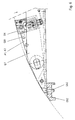
- Fig. 1 and Fig. 2 locking arrangement shows three different Locking devices together in their respective holding positions. Not all elements are drawn in each case for the sake of clarity to improve the pictures.
- the first locking arrangement is arranged at the end of a cross member QT, which at least in the region of the locking arrangement as a U-shaped Profile with surfaces QT-O, QT-R and QT-U executed and in the direction of travel LR, i. opposite the wall QT-R at least partially, preferably is predominantly or completely open.
- a locking housing VG1 contains as a locking element of the first Locking device a pivot VK, which vertically over the upper Surface of the lock housing VG1 protrudes and into a lower opening a corner fitting EB1 of a container protrudes.
- a pivot VK By twisting the Pivot about a vertical axis by means of the locking lever VH is the Fitting locked with the lock housing.
- Trunnion latches are commonly known and commonly used, so on details the trunnion lock will not be discussed here.
- a third locking device with a Locking pin SB1 housed.
- the socket pin projects horizontally against the Direction of travel beyond the lock housing VG1 and can in a frontal opening of a non-bevelled corner fitting engage.
- the lock housing VG1 is held on a pivot arm, which is constructed of two parallel horizontal arm plates A1, A2, which with the locking housing are preferably welded.
- the swivel arm is about a vertical pivot axis SA in the direction of arrow AS horizontally from the sketched holding position of the first and third locking device pivotable.
- the arm plates A1, A2 extend within the profile of the cross member QT parallel to its horizontal walls QT-O, QT-U and are applied on this or this with a small distance opposite.
- a second horizontal locking pin SB2 as a locking element of a second locking device is fixed to a plate-shaped carrier T2 connected.
- the carrier T2 has one of the rear wall QT-R of the cross member profile remote edge, which runs obliquely against the rear wall QT-R and in the sketched holding position of the second locking device within a permissible spin arc around the kingpin of the chassis support runs and thereby closely conforms to the circular arc.
- the second plug SB2 protrudes horizontally over the through the rear wall QT-R the cross member formed stop edge for a container end edge addition and can interfere with a beveled corner of a 45 'HC container.
- the wave SW is carried out in the example sketched two sides flattened. A allows relative radial displacement of the pivot arm A1, A2 to the outside likewise the relative pivoting.
- the support plate T2 is in relation to the vertical pivot axis SA achsialer Direction spaced between the arm plates A1, A2 and parallel to these.
- To stabilize the various locking devices against vertical forces are horizontal support plates SP1, SP2 with the rear wall QT-R the cross member welded, which in the axial direction between the Beam 2 and against the horizontal walls QT-O, QT-U of the cross member the Tightly enclose arm plates A2 or A1.
- the spacers also as stepped discs be formed and larger in relation to the shaft diameter Holes of the arm plates A1, A2 can rest.
- the locking pins SB1, SB2 are in Fig. 1 and Fig. 2 as in the sketched holding position drawn aligned parallel to the longitudinal direction LR of the chassis.
- the socket pin can also approximately tangential to the pivot axis be formed to pivot in the openings of the corner fittings show as little side play in the openings.
- Fig. 5 shows in section with a view transverse to the vehicle longitudinal axis a variant with horizontally pivoting arm SWH in opposite to the direction of travel open U-shape
- Fig. 8 a vertically pivotable Swing arm SWH with downwardly open U-shape.
- Fig. 5 shows in plan view a situation in which the third locking device with the first locking pin SB1 in an end opening of a non-tapered corner fitting EB3 e.g. a 20 'or 40' HC container engages and the support plate T2 by a small tilt angle against the 2 sketched position is pivoted, but unchanged from the arm plates A1, A2 is completely covered.
- the support plate T2 with the locking pin SB2 can also be completely out of range at a greater angle be swung out of the swivel arm.
- the locking devices can in their respective holding positions be advantageously held by securing devices, in particular by the horizontal pivoting movement about the vertical pivot axis SA a fuse by blocking the pivoting movement especially is advantageous.
- a fuse can, for example, by a flush in Locking holes SH of cross member and support plate T2 or Swivel arm A1, A2 insertable safety pin SI.
- the cross member QT extends laterally with its rear wall QT-R substantially up to the socket pin SB2, allowing a high stiffener against Vertical forces is given.
- the cross member may end in front of the socket pin SB2 or embrace this.
- An additional support of the locking devices is provided by the provided in the end regions of the cross member Support plates SP1, SP2.
- FIGS. 3 and 4 show an advantageous embodiment of a locking housing VG1, which by pivoting the pivot VK in an area between upper and lower boundary surfaces of the lock housing, the vertical not over the arm plates A1 and A2 down or survive above, brought in a particularly flat shape and thus also be pivoted far into the open in the direction of travel profile of the cross member can.
- the locking pin which held in a pin carrier and is rotatably guided, about a horizontal tilting axis KA is tiltable and thereby in the outlined in Fig. 3 upright position by a releasable latch RI is supported.
- the bolt is according to the example outlined by a the first locking pin SB1 facing away from and firmly connected to this and a vertical Axis BA formed in the locking housing pivotable extension, which is supported on the bottom of the locking housing and in a Recess AU of the pin ZT rests.
- the recess AU secures at the same time the plug pin SB1 against pivoting about the axis BA.
- FIGS. 9 to 11 are largely similar to FIGS already based on the Fig. 1 to Fig. 6 explained preferred embodiment ajar.
- the relevant previous explanations are valid in scope the correspondences essentially also for the following in detail explained further comments.
- the construction of the cross member QT as in the direction of travel at least partially open profile, the Structure of a pivoting arm of two parallel plates A1, A2 and a lock housing with a lowerable pivot as the first locking device accepted.
- the first locking device an often referred to as a twist-lock, vertically in a container corner fitting engaging from below and lockable by rotation Pins understood, whereas as the second and third locking device serve horizontal locking pins.
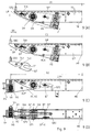
- FIG. 9 An advantageous embodiment is in Fig. 9 in different positions and views outlined, in which case the second and third locking device in the form of a pin SB2 are identical.
- the locking pin is open a bolt carrier BT arranged, which as a slide in a transverse to Slidable longitudinal direction LR of the chassis extending sliding direction SR is and removed by this shift from the cross member and / or set in at least two different positions in the sliding direction can be.
- the determination can for example by a safety pin SIA, which through openings in the cross member and the bolt carrier be upheld.
- the bolt carrier BT is in the sketch of FIG. 9 (A). in a working position for holding an oversized 45 'HC container as a second container type with bevelled corner fittings.
- the lateral Distance D1 of the pin SB2 from the center plane ME of the chassis is then about 1045 mm.
- the socket pin SB2 is one Distance difference DS further outward at a distance D2 from the central longitudinal plane ME of the chassis with D2 about 1130 mm and can be used as a third locking device for mounting a standard HC container as the third container type serve.
- Locking and unlocking a second or third type container The chassis is made by moving the cross member in the direction of arrow TS parallel to the vehicle longitudinal direction LR, without pivoting the bolt carrier BT is required.
- Such a procedure for locking and Unlocking is also possible with the previously described embodiments and advantageous, in which case the possibly given pivotability of the the bolt-carrying arm only to change the locking device serves.
- the longitudinal displacement of the front cross member in longitudinal guides is known per se and can advantageously be operated hydraulically be.
- the first locking device with a vertical in a corner fitting of a Containers first type engaging plug VK in a lock housing VG is in a parking position by a in Fig. 9 (A) and Fig. 9 (B) second safety pin SIP set.
- the cross member at least sections in the direction of travel, d. H. the crossmember rear wall QTR facing away, above and attached to a pivoting arm locking housing VG of the first locking device in the parking position between upper QTO and lower QTU plate of the cross member and within the spin circle DR is located around the kingpin of the chassis support. in this connection can, as described in these previous examples, the locking pin swung from the upright position in the locking housing be.
- the bolt carrier BT which is shown isolated between Fig. 9 (B) and Fig. 9 (C) is, this can be taken from the cross member and in his in Fig. 9 (C) and Fig. 9 (D) sketched parking position between upper and lower plate QTO, QTU be brought to the cross member.
- the isolated representation of the bolt carrier clearly two openings TL1, TL2 can be seen through the carrier plate, which for fixing the bolt carrier in the two working positions as shown in Fig. 9 (A) and Fig. 9 (B).
- a recess TF surrounds in the working position of Fig. 9 (A) and the parking position of Fig. 9 (C), the pivot axis SA.
- the bolt facing away from the opening of the recess can for Fuse against unintentional failure bridged or completed be.
- the lateral displaceability of the bolt carrier from the position according to FIG. 9 (A) with complete within a spin circle DR with radius 2040 mm around the king seat of the landing gear of the undercarriage on a towing vehicle lying latching arrangement leads through the lateral displacement of the Bolzenanis in the position of FIG. 9 (B) to a slight projection of the bolt carrier via its position according to FIG. 9 (A).
- the resulting supernatant of the container at the rear of the vehicle is tolerable with approx. 60 mm as a rule.
- Fig. 9 (D) From the front view of Fig. 9 (D) are further the previously mentioned Embodiments of the invention similar construction details visible.
- the swivel arm, on which the lock housing VG is externally attached can be made of two vertically spaced arm plates A1, A2 exist, but also additional vertical Wall sections between the arm plates A1, A2 included for stiffening.
- Breakthroughs ALA, ALP in plates A1, A2 serve to define the Swing arm in the working position of Fig. 9 (C), (D) or the parking position according to Fig. 9 (A), (B).
- Fig. 10 a modification is shown in which in one of Fig. 9 (C) corresponding Working position of the first locking device with the vertical Do not pin the sliding bolt carrier with the plug pin SB pulled out of the cross member, but in the position of FIG. 9 (A) is left and the lock housing lies to the side of it is assumed that the lock housing VG with the locking pin in the correct distance to the vehicle center plane ME, which in the usual Container fittings equal to D2, laterally next to the one in the working position Figure 9 (C) located bolt carrier finds place. If the geometry of the Locking housing does not allow, can also be provided, the Bolzenour beyond the working position of FIG.
- Fig. 9 (C) out in a closer to Center plane ME lying park position to move and / or the lock housing not exactly at the side of the bolt carrier but in the longitudinal direction LR and offset towards the center plane ME and / or the locking housing beveled on the Corner facing the bolt carrier.
- the lock housing is in turn on the pivot arm about the pivot axis SA pivotable in the direction of arrow AS and can from the sketched working position, in which by vertically engaging in Eckbehave locking pin VK a first container type (ISO) can be kept in one Parking position of Fig. 9 (A), (B) outlined manner are pivoted to the plug pin SB2 in one of its two working positions accordingly Fig. 9 (A), (B) to a HC container of the second or third container type hold.
- the embodiment of Fig. 10 is also in conjunction with an additional pivotable about the pivot axis SA Bolzenitati BT advantageously realized.
- the socket pin SB1 can advantageously with as in previous embodiments with a lock housing VG1 connected to a twist-lock spigot be.
- the base of the pin SB1 which in the example sketched the rear wall GR of the combination lock housing VG1 is opposite the base of the fixed pin SB against the direction of travel at least offset by the bolt length BL of the plug pin SB.
- the combination lock housing VG1 is outlined about the pivot axis SA Working position in a parking position according to Fig. 9 (A), (B) pivotable.
- Fig. 9 are also advantageous relative positions with respect to the central longitudinal plane ME illustrates.
- the distance D3 of the pivot axis of the pivot arm the first locking device is preferably between 60% and 90 % of the distance D1 of the pin SB2 from this central longitudinal plane.
- the first locking unit is located in its parking position advantageously at a distance D4 from the central longitudinal plane that is less than 50%, preferably between 20% and 40% of D1.
Landscapes
- Engineering & Computer Science (AREA)
- Transportation (AREA)
- Mechanical Engineering (AREA)
- Body Structure For Vehicles (AREA)
- Auxiliary Devices For And Details Of Packaging Control (AREA)
- Lock And Its Accessories (AREA)
- Filling Of Jars Or Cans And Processes For Cleaning And Sealing Jars (AREA)
- Wrapping Of Specific Fragile Articles (AREA)
- Automatic Assembly (AREA)
- Automobile Manufacture Line, Endless Track Vehicle, Trailer (AREA)
- Supplying Of Containers To The Packaging Station (AREA)
- Container Filling Or Packaging Operations (AREA)
- Fittings On The Vehicle Exterior For Carrying Loads, And Devices For Holding Or Mounting Articles (AREA)
Priority Applications (1)
| Application Number | Priority Date | Filing Date | Title |
|---|---|---|---|
| DK02021520T DK1300285T3 (da) | 2001-10-02 | 2002-09-26 | Indretning til fastholdelse af forskellige containertyper på en undervogn |
Applications Claiming Priority (4)
| Application Number | Priority Date | Filing Date | Title |
|---|---|---|---|
| DE10148704 | 2001-10-02 | ||
| DE2001148704 DE10148704C1 (de) | 2001-10-02 | 2001-10-02 | Anordnung zur Halterung unterschiedlicher Container-Typen auf einem Fahrgestell |
| DE10232561 | 2002-07-18 | ||
| DE10232561A DE10232561A1 (de) | 2001-10-02 | 2002-07-18 | Anordnung zur Halterung unterschiedlicher Container-Typen auf einem Fahrgestell |
Publications (2)
| Publication Number | Publication Date |
|---|---|
| EP1300285A1 EP1300285A1 (de) | 2003-04-09 |
| EP1300285B1 true EP1300285B1 (de) | 2005-06-08 |
Family
ID=26010283
Family Applications (1)
| Application Number | Title | Priority Date | Filing Date |
|---|---|---|---|
| EP02021520A Expired - Lifetime EP1300285B1 (de) | 2001-10-02 | 2002-09-26 | Anordnung zur Halterung unterschiedlicher Container-Typen auf einem Fahrgestell |
Country Status (6)
| Country | Link |
|---|---|
| EP (1) | EP1300285B1 (da) |
| AT (1) | ATE297326T1 (da) |
| DE (2) | DE10232561A1 (da) |
| DK (1) | DK1300285T3 (da) |
| ES (1) | ES2242809T3 (da) |
| PT (1) | PT1300285E (da) |
Families Citing this family (5)
| Publication number | Priority date | Publication date | Assignee | Title |
|---|---|---|---|---|
| EP1621399A1 (de) * | 2004-07-28 | 2006-02-01 | Holger Stuht | Vorrichtung zur Änderung der Verriegelungshöhe eines Containers auf einem Fahrzeugchassis |
| DE102004045665B4 (de) * | 2004-09-18 | 2008-01-31 | Jost-Werke Gmbh & Co. Kg | Querträger zum stirnseitigen Einbau in ein Chassis |
| DE102005050928B4 (de) * | 2005-10-21 | 2009-04-09 | Fahrzeugwerk Bernard Krone Gmbh | Fahrgestell für Container, Aufbauten und dergleichen Ladungsbehälter |
| EP2379369B1 (en) * | 2008-12-17 | 2014-02-26 | Volvo Lastvagnar AB | Carrier device for coupling different kinds of payload bodies |
| EP4335696A1 (en) | 2023-10-19 | 2024-03-13 | Hiab AB | A locking assembly |
Family Cites Families (8)
| Publication number | Priority date | Publication date | Assignee | Title |
|---|---|---|---|---|
| DE9114904U1 (de) * | 1991-11-30 | 1993-03-25 | Schulz, Gerd, 34289 Zierenberg | Vorrichtung zur Verriegelung eines Containers |
| DE19606263A1 (de) * | 1995-03-22 | 1996-09-26 | Jost Werke Ag | Vorrichtung zur Verriegelung eines Containers an einem Fahrzeugchassis |
| DE29606845U1 (de) * | 1996-04-16 | 1996-07-04 | alli Frischdienst-Zentrale Nord GmbH. & CO., 30559 Hannover | Hilfsrahmen für einen Lastkraftwagen für den Transport von Wechselbehältern |
| DE20010144U1 (de) * | 1999-06-29 | 2000-12-14 | R. Metternich Metallbau GmbH, 21079 Hamburg | Vorrichtung zur Befestigung eines überlangen Containers auf einem Transportfahrzeug |
| NL1013424C2 (nl) * | 1999-10-29 | 2001-05-02 | Contar B V | Wegvoertuig voor het vervoeren van containers. |
| DE20012977U1 (de) * | 2000-07-27 | 2001-02-08 | R. Metternich Metallbau GmbH, 21107 Hamburg | Vorrichtung zur Befestigung eines überlangen Containers auf einem Transportfahrzeug |
| DE10047093A1 (de) * | 2000-09-21 | 2002-05-02 | Jost Werke Gmbh & Co Kg | Vorrichtung zur Verriegelung eines Containers an einem Fahrzeugchassis |
| DE10108096A1 (de) * | 2001-02-19 | 2002-09-12 | Juergen Ehring | Verriegelungssystem für Fracht auf Fahrzeugen und seine Komponenten |
-
2002
- 2002-07-18 DE DE10232561A patent/DE10232561A1/de not_active Withdrawn
- 2002-09-26 EP EP02021520A patent/EP1300285B1/de not_active Expired - Lifetime
- 2002-09-26 PT PT02021520T patent/PT1300285E/pt unknown
- 2002-09-26 AT AT02021520T patent/ATE297326T1/de not_active IP Right Cessation
- 2002-09-26 DE DE50203323T patent/DE50203323D1/de not_active Expired - Lifetime
- 2002-09-26 DK DK02021520T patent/DK1300285T3/da active
- 2002-09-26 ES ES02021520T patent/ES2242809T3/es not_active Expired - Lifetime
Also Published As
| Publication number | Publication date |
|---|---|
| EP1300285A1 (de) | 2003-04-09 |
| DE50203323D1 (de) | 2005-07-14 |
| PT1300285E (pt) | 2005-09-30 |
| ES2242809T3 (es) | 2005-11-16 |
| DK1300285T3 (da) | 2005-08-22 |
| ATE297326T1 (de) | 2005-06-15 |
| DE10232561A1 (de) | 2004-02-05 |
Similar Documents
| Publication | Publication Date | Title |
|---|---|---|
| EP2261066B1 (de) | Anhängevorrichtung | |
| EP0695655A1 (de) | Zugvorrichtung und Verriegelungsvorrichtung | |
| EP0688687A1 (de) | Hebevorrichtung | |
| DE4413444A1 (de) | Laderampe für Kraftfahrzeuge | |
| DE3322551C2 (de) | Zwischenstück zum Ausschalten der Seitenbeweglichkeit von Unterlenkern eines Ackerschleppers | |
| EP1300285B1 (de) | Anordnung zur Halterung unterschiedlicher Container-Typen auf einem Fahrgestell | |
| EP0985563B1 (de) | Hebevorrichtung | |
| EP1354790B1 (de) | Klapprunge mit Riegeleinrichtung | |
| EP3666591A1 (de) | Containerverriegelung, frontausschub eines fahrgestells mit einer solchen containerverriegelung und verriegelungsanordnung | |
| EP1544003B1 (de) | Anhängekupplung für Personenkraftfahrzeuge | |
| EP0844208B1 (de) | Wagenheber | |
| EP0388363B1 (de) | Anhängevorrichtung für Fahrzeuge | |
| DE10047093A1 (de) | Vorrichtung zur Verriegelung eines Containers an einem Fahrzeugchassis | |
| DE2736222C3 (de) | Hubfangverschluß | |
| DE19520893A1 (de) | Kopfstützenklappvorrichtung | |
| DE9416308U1 (de) | Wechselbehälter | |
| EP0545019A1 (de) | Vorrichtung zur Verriegelung eines Containers an einem Fahrzeugchassis | |
| DE102021133431A1 (de) | Klappvorrichtung für Fahrzeugheckträger und Fahrzeugheckträger mit einer solchen Klappvorrichtung | |
| DE20101630U1 (de) | Transport- und/oder Lagerbehälter und dafür geeigneter Einbaurahmen | |
| DE10148704C1 (de) | Anordnung zur Halterung unterschiedlicher Container-Typen auf einem Fahrgestell | |
| DE69120987T2 (de) | Türverriegelung für Behälter | |
| EP2583881B1 (de) | Lenkeinrichtung für einen Kamerawagen, und entsprechend ausgerüsteter Kamerawagen | |
| DE3240919A1 (de) | Eisenbahn-trichterwagen | |
| DE68907799T4 (de) | Hubvorrichtung. | |
| DE102024123336A1 (de) | Anhängekupplung |
Legal Events
| Date | Code | Title | Description |
|---|---|---|---|
| PUAI | Public reference made under article 153(3) epc to a published international application that has entered the european phase |
Free format text: ORIGINAL CODE: 0009012 |
|
| AK | Designated contracting states |
Kind code of ref document: A1 Designated state(s): AT BE BG CH CY CZ DE DK EE ES FI FR GB GR IE IT LI LU MC NL PT SE SK TR |
|
| AX | Request for extension of the european patent |
Extension state: AL LT LV MK RO SI |
|
| 17P | Request for examination filed |
Effective date: 20031009 |
|
| AKX | Designation fees paid |
Designated state(s): AT BE BG CH CY CZ DE DK EE ES FI FR GB GR IE IT LI LU MC NL PT SE SK TR |
|
| 17Q | First examination report despatched |
Effective date: 20040202 |
|
| GRAP | Despatch of communication of intention to grant a patent |
Free format text: ORIGINAL CODE: EPIDOSNIGR1 |
|
| GRAS | Grant fee paid |
Free format text: ORIGINAL CODE: EPIDOSNIGR3 |
|
| GRAA | (expected) grant |
Free format text: ORIGINAL CODE: 0009210 |
|
| AK | Designated contracting states |
Kind code of ref document: B1 Designated state(s): AT BE BG CH CY CZ DE DK EE ES FI FR GB GR IE IT LI LU MC NL PT SE SK TR |
|
| PG25 | Lapsed in a contracting state [announced via postgrant information from national office to epo] |
Ref country code: CZ Free format text: LAPSE BECAUSE OF FAILURE TO SUBMIT A TRANSLATION OF THE DESCRIPTION OR TO PAY THE FEE WITHIN THE PRESCRIBED TIME-LIMIT Effective date: 20050608 Ref country code: TR Free format text: LAPSE BECAUSE OF FAILURE TO SUBMIT A TRANSLATION OF THE DESCRIPTION OR TO PAY THE FEE WITHIN THE PRESCRIBED TIME-LIMIT Effective date: 20050608 Ref country code: IE Free format text: LAPSE BECAUSE OF FAILURE TO SUBMIT A TRANSLATION OF THE DESCRIPTION OR TO PAY THE FEE WITHIN THE PRESCRIBED TIME-LIMIT Effective date: 20050608 Ref country code: SK Free format text: LAPSE BECAUSE OF FAILURE TO SUBMIT A TRANSLATION OF THE DESCRIPTION OR TO PAY THE FEE WITHIN THE PRESCRIBED TIME-LIMIT Effective date: 20050608 Ref country code: EE Free format text: LAPSE BECAUSE OF FAILURE TO SUBMIT A TRANSLATION OF THE DESCRIPTION OR TO PAY THE FEE WITHIN THE PRESCRIBED TIME-LIMIT Effective date: 20050608 |
|
| REG | Reference to a national code |
Ref country code: GB Ref legal event code: FG4D Free format text: NOT ENGLISH |
|
| REG | Reference to a national code |
Ref country code: CH Ref legal event code: EP |
|
| REF | Corresponds to: |
Ref document number: 50203323 Country of ref document: DE Date of ref document: 20050714 Kind code of ref document: P |
|
| REG | Reference to a national code |
Ref country code: IE Ref legal event code: FG4D Free format text: LANGUAGE OF EP DOCUMENT: GERMAN |
|
| REG | Reference to a national code |
Ref country code: DK Ref legal event code: T3 |
|
| GBT | Gb: translation of ep patent filed (gb section 77(6)(a)/1977) |
Effective date: 20050815 |
|
| PG25 | Lapsed in a contracting state [announced via postgrant information from national office to epo] |
Ref country code: BG Free format text: LAPSE BECAUSE OF FAILURE TO SUBMIT A TRANSLATION OF THE DESCRIPTION OR TO PAY THE FEE WITHIN THE PRESCRIBED TIME-LIMIT Effective date: 20050908 Ref country code: GR Free format text: LAPSE BECAUSE OF FAILURE TO SUBMIT A TRANSLATION OF THE DESCRIPTION OR TO PAY THE FEE WITHIN THE PRESCRIBED TIME-LIMIT Effective date: 20050908 Ref country code: SE Free format text: LAPSE BECAUSE OF FAILURE TO SUBMIT A TRANSLATION OF THE DESCRIPTION OR TO PAY THE FEE WITHIN THE PRESCRIBED TIME-LIMIT Effective date: 20050908 |
|
| PG25 | Lapsed in a contracting state [announced via postgrant information from national office to epo] |
Ref country code: AT Free format text: LAPSE BECAUSE OF NON-PAYMENT OF DUE FEES Effective date: 20050926 Ref country code: CY Free format text: LAPSE BECAUSE OF FAILURE TO SUBMIT A TRANSLATION OF THE DESCRIPTION OR TO PAY THE FEE WITHIN THE PRESCRIBED TIME-LIMIT Effective date: 20050926 |
|
| PG25 | Lapsed in a contracting state [announced via postgrant information from national office to epo] |
Ref country code: LU Free format text: LAPSE BECAUSE OF NON-PAYMENT OF DUE FEES Effective date: 20050930 Ref country code: MC Free format text: LAPSE BECAUSE OF NON-PAYMENT OF DUE FEES Effective date: 20050930 |
|
| REG | Reference to a national code |
Ref country code: PT Ref legal event code: SC4A Effective date: 20050727 |
|
| REG | Reference to a national code |
Ref country code: ES Ref legal event code: FG2A Ref document number: 2242809 Country of ref document: ES Kind code of ref document: T3 |
|
| REG | Reference to a national code |
Ref country code: IE Ref legal event code: FD4D |
|
| ET | Fr: translation filed | ||
| PLBE | No opposition filed within time limit |
Free format text: ORIGINAL CODE: 0009261 |
|
| STAA | Information on the status of an ep patent application or granted ep patent |
Free format text: STATUS: NO OPPOSITION FILED WITHIN TIME LIMIT |
|
| 26N | No opposition filed |
Effective date: 20060309 |
|
| PG25 | Lapsed in a contracting state [announced via postgrant information from national office to epo] |
Ref country code: CH Free format text: LAPSE BECAUSE OF NON-PAYMENT OF DUE FEES Effective date: 20060930 Ref country code: LI Free format text: LAPSE BECAUSE OF NON-PAYMENT OF DUE FEES Effective date: 20060930 |
|
| REG | Reference to a national code |
Ref country code: CH Ref legal event code: PL |
|
| REG | Reference to a national code |
Ref country code: DE Ref legal event code: R082 Ref document number: 50203323 Country of ref document: DE Representative=s name: GERHARD WEBER, DE |
|
| REG | Reference to a national code |
Ref country code: DE Ref legal event code: R082 Ref document number: 50203323 Country of ref document: DE Representative=s name: BAUR & WEBER PATENTANWAELTE PARTG MBB, DE Effective date: 20120402 Ref country code: DE Ref legal event code: R082 Ref document number: 50203323 Country of ref document: DE Representative=s name: BAUR & WEBER PATENTANWAELTE, DE Effective date: 20120402 Ref country code: DE Ref legal event code: R081 Ref document number: 50203323 Country of ref document: DE Owner name: SCHMITZ CARGOBULL GOTHA GMBH, DE Free format text: FORMER OWNER: SCHMITZ GOTHA FAHRZEUGWERKE GMBH, 99867 GOTHA, DE Effective date: 20120402 |
|
| REG | Reference to a national code |
Ref country code: DE Ref legal event code: R082 Ref document number: 50203323 Country of ref document: DE Representative=s name: BAUR & WEBER PATENTANWAELTE PARTG MBB, DE Ref country code: DE Ref legal event code: R082 Ref document number: 50203323 Country of ref document: DE Representative=s name: BAUR & WEBER PATENTANWAELTE, DE |
|
| REG | Reference to a national code |
Ref country code: FR Ref legal event code: PLFP Year of fee payment: 14 |
|
| PGFP | Annual fee paid to national office [announced via postgrant information from national office to epo] |
Ref country code: GB Payment date: 20150922 Year of fee payment: 14 Ref country code: ES Payment date: 20150923 Year of fee payment: 14 Ref country code: PT Payment date: 20150923 Year of fee payment: 14 Ref country code: FI Payment date: 20150921 Year of fee payment: 14 |
|
| PGFP | Annual fee paid to national office [announced via postgrant information from national office to epo] |
Ref country code: FR Payment date: 20150923 Year of fee payment: 14 |
|
| PGFP | Annual fee paid to national office [announced via postgrant information from national office to epo] |
Ref country code: DK Payment date: 20150923 Year of fee payment: 14 |
|
| PGFP | Annual fee paid to national office [announced via postgrant information from national office to epo] |
Ref country code: IT Payment date: 20150925 Year of fee payment: 14 |
|
| REG | Reference to a national code |
Ref country code: DK Ref legal event code: EBP Effective date: 20160930 |
|
| PG25 | Lapsed in a contracting state [announced via postgrant information from national office to epo] |
Ref country code: FI Free format text: LAPSE BECAUSE OF NON-PAYMENT OF DUE FEES Effective date: 20160926 |
|
| GBPC | Gb: european patent ceased through non-payment of renewal fee |
Effective date: 20160926 |
|
| PG25 | Lapsed in a contracting state [announced via postgrant information from national office to epo] |
Ref country code: PT Free format text: LAPSE BECAUSE OF NON-PAYMENT OF DUE FEES Effective date: 20170327 |
|
| REG | Reference to a national code |
Ref country code: FR Ref legal event code: ST Effective date: 20170531 |
|
| PG25 | Lapsed in a contracting state [announced via postgrant information from national office to epo] |
Ref country code: FR Free format text: LAPSE BECAUSE OF NON-PAYMENT OF DUE FEES Effective date: 20160930 Ref country code: GB Free format text: LAPSE BECAUSE OF NON-PAYMENT OF DUE FEES Effective date: 20160926 |
|
| PG25 | Lapsed in a contracting state [announced via postgrant information from national office to epo] |
Ref country code: IT Free format text: LAPSE BECAUSE OF NON-PAYMENT OF DUE FEES Effective date: 20160926 |
|
| PG25 | Lapsed in a contracting state [announced via postgrant information from national office to epo] |
Ref country code: DK Free format text: LAPSE BECAUSE OF NON-PAYMENT OF DUE FEES Effective date: 20160930 |
|
| PGFP | Annual fee paid to national office [announced via postgrant information from national office to epo] |
Ref country code: NL Payment date: 20170925 Year of fee payment: 16 Ref country code: BE Payment date: 20170925 Year of fee payment: 16 |
|
| PG25 | Lapsed in a contracting state [announced via postgrant information from national office to epo] |
Ref country code: ES Free format text: LAPSE BECAUSE OF NON-PAYMENT OF DUE FEES Effective date: 20160927 |
|
| REG | Reference to a national code |
Ref country code: ES Ref legal event code: FD2A Effective date: 20181123 |
|
| REG | Reference to a national code |
Ref country code: NL Ref legal event code: MM Effective date: 20181001 |
|
| REG | Reference to a national code |
Ref country code: BE Ref legal event code: MM Effective date: 20180930 |
|
| PG25 | Lapsed in a contracting state [announced via postgrant information from national office to epo] |
Ref country code: NL Free format text: LAPSE BECAUSE OF NON-PAYMENT OF DUE FEES Effective date: 20181001 |
|
| PG25 | Lapsed in a contracting state [announced via postgrant information from national office to epo] |
Ref country code: BE Free format text: LAPSE BECAUSE OF NON-PAYMENT OF DUE FEES Effective date: 20180930 |
|
| PGFP | Annual fee paid to national office [announced via postgrant information from national office to epo] |
Ref country code: DE Payment date: 20210930 Year of fee payment: 20 |
|
| REG | Reference to a national code |
Ref country code: DE Ref legal event code: R071 Ref document number: 50203323 Country of ref document: DE |