EP1300519A1 - Hydraulischer kreislauf und notbetriebsverfahren eines anbaugerätes - Google Patents
Hydraulischer kreislauf und notbetriebsverfahren eines anbaugerätes Download PDFInfo
- Publication number
- EP1300519A1 EP1300519A1 EP01934472A EP01934472A EP1300519A1 EP 1300519 A1 EP1300519 A1 EP 1300519A1 EP 01934472 A EP01934472 A EP 01934472A EP 01934472 A EP01934472 A EP 01934472A EP 1300519 A1 EP1300519 A1 EP 1300519A1
- Authority
- EP
- European Patent Office
- Prior art keywords
- washing
- waste
- container
- bedplate
- collection
- Prior art date
- Legal status (The legal status is an assumption and is not a legal conclusion. Google has not performed a legal analysis and makes no representation as to the accuracy of the status listed.)
- Granted
Links
Images
Classifications
-
- E—FIXED CONSTRUCTIONS
- E02—HYDRAULIC ENGINEERING; FOUNDATIONS; SOIL SHIFTING
- E02F—DREDGING; SOIL-SHIFTING
- E02F9/00—Component parts of dredgers or soil-shifting machines, not restricted to one of the kinds covered by groups E02F3/00 - E02F7/00
- E02F9/20—Drives; Control devices
- E02F9/22—Hydraulic or pneumatic drives
- E02F9/226—Safety arrangements, e.g. hydraulic driven fans, preventing cavitation, leakage, overheating
-
- E—FIXED CONSTRUCTIONS
- E02—HYDRAULIC ENGINEERING; FOUNDATIONS; SOIL SHIFTING
- E02F—DREDGING; SOIL-SHIFTING
- E02F9/00—Component parts of dredgers or soil-shifting machines, not restricted to one of the kinds covered by groups E02F3/00 - E02F7/00
- E02F9/20—Drives; Control devices
- E02F9/22—Hydraulic or pneumatic drives
-
- E—FIXED CONSTRUCTIONS
- E02—HYDRAULIC ENGINEERING; FOUNDATIONS; SOIL SHIFTING
- E02F—DREDGING; SOIL-SHIFTING
- E02F9/00—Component parts of dredgers or soil-shifting machines, not restricted to one of the kinds covered by groups E02F3/00 - E02F7/00
- E02F9/20—Drives; Control devices
- E02F9/22—Hydraulic or pneumatic drives
- E02F9/2278—Hydraulic circuits
- E02F9/2282—Systems using center bypass type changeover valves
-
- E—FIXED CONSTRUCTIONS
- E02—HYDRAULIC ENGINEERING; FOUNDATIONS; SOIL SHIFTING
- E02F—DREDGING; SOIL-SHIFTING
- E02F9/00—Component parts of dredgers or soil-shifting machines, not restricted to one of the kinds covered by groups E02F3/00 - E02F7/00
- E02F9/20—Drives; Control devices
- E02F9/22—Hydraulic or pneumatic drives
- E02F9/2278—Hydraulic circuits
- E02F9/2285—Pilot-operated systems
Definitions
- the present specification refers to a Patent: Application regarding a mixed vehicle for collecting waste and washing igloo type containers, whose purpose is to permit the collection and evacuation of waste contained in igloo type containers, generally for the recovery of glass, as well as washing an disinfecting the container using devices fitted to the vehicle itself.
- said vehicle may be converted into a fixed washing plant if the components carried by the vehicle are deposited on the ground, simultaneously performing container disinfection, equal to vehicles applicable to these operations.
- This invention is applicable to the industry dedicated to the manufacture of equipment, vehicles and auxiliary components for the collection of waste deposited in containers.
- container loading and unloading may or may not be automatic and moreover, in these cases, the washing processes may be controlled by means of programmable robots.
- Systems are even known which incorporate probes to continually know the status of the cleaning cycle and timers to set times.
- Patent FR 2,645,775 a VEHICLE TO WASH CONTAINERS, PARTICULARLY CONTAINERS FOR THE AUTOMATIC COLLECTION OF URBAN WASTE is known, said vehicle being provided with a washing tunnel with a rear door and loading means to introduce the containers in said tunnel.
- Cleaning is carried out by means of a programmed robot, remotely activated and which supports a washing mechanism and a chamber.
- All the operations, washing and loading-unloading may follow an automatic programmed cycle and be remotely activated by an operator mainly thanks to the images sent by the camera.
- Patent GB 2,196,446 a DEVICE FOR THE CLEANING OF A TANK INTERIOR is known which consists of a set of injectors located inside the tank and which may move in different directions and at different heights thanks to remote control means.
- the system has a predetermined program and includes probes indicating the liquid level in the tank and a timer which sends a process stopping signal after a determined period of time.
- the US Patent number 5,329,949 describes a HOME WASHING SYSTEM WITH RADIOFREQUENCY REMOTE CONTROL and is configured as an automatic washing system for cars, with remote control activated by an infrared position probe, applicable to any private garage or similar building.
- the user activates the washing system and opening of the garage door.
- the system processor consists of a programmed microcontroller to receive signals from the garage door, a radiofrequency transmitter-emitter, a thermistor and an infrared position probe.
- Patent FR 2,608,076 an ASSEMBLY FOR WASHING CARRIAGES, CONTAINERS AND CISTERNS is known, which is fitted over a platform and consists of a power unit and the means necessary to wash containers, that is, aspiration pumps, water tanks, boilers, water conduits, etc.
- the system is characterised in that it may be remotely controlled by a single person, who after activating the power unit, may activate the different operations, from change of detergent to selection of the recovery tank.
- the assembly has devices for coupling to a truck or similar devices for its displacement.
- Patent FR 2,697,511 describes a PORTABLE DEVICE FOR CLEANING CONTAINERS, consisting of a portable device fitted on a container washing vehicle, consisting of liquid tanks, a mechanical lift and internal and external container cleaning ramps.
- the cleaning cycle is controlled by electrically operated valves which are in turn activated by a programmable robot or a microprocessor.
- Patent E93400518 describes a FACILITY FOR THE CLEANING OF CONTAINERS, SUCH AS RUBBISH BINS, which is configured as from a washing tray, provided with an opening for container passage, loading means to introduce at least one container inside the tray and to remove one of them at the end of the washing operation, having airtight closing means for each opening and a plurality of washing heads arranged inside said tray, at least one of said washing heads being arranged in such a way as to project pressurised water inside the container introduced in the tray, whilst at least one of the other washing heads is arranged so as to project water over the outside walls of said container.
- the central washing head is fixed to a mechanical dragging device, permitting it to be moved to the interior of said container in the direction of its depth and also in the two perpendicular directions.
- ESPECIALLY RUBBISH are known, which are configured as water deposits which have washing heads supplied with washing liquid, specifically water under pressure, being arranged in a washing tray in the rear part of the vehicle, having an opening for the introduction of containers, some loading means to introduce the containers inside the tray through the opening and means to close the latter, said means likewise being loading means and preferably having the shape of a tub.
- Patent ES0527357 describes a CONTAINER AND BIN WASHING EQUIPMENT which may be located over a vehicle chassis, consisting of a cleaning roller which rotates and is displaced following the inside walls of the container, as well as a mechanism which lifts the containers to be cleaned, as well as the washing tub door and afterwards, and then lowers the containers when finishing the washing stage, having a pump which takes clean water from a general tub and projects it under pressure through the washing circuit.
- the invention is provided with a spray unit consisting of a jet fed through a conduit by the boiler pressurising unit, the base of the jet being inserted in a support, and one or several water deposits.
- the US Patent number 4,694,846 describes a SYSTEM FOR THE CLEANING AND DISINFECTING OF RUBBISH CONTAINERS, specifically formed by a vehicle incorporating an air container supplied by the compressor and connected to another container with water and disinfectant, which is supplied with air until the necessary pressure is reached to project the mixture of water, air and disinfectant through the nozzles directed towards the inside surface of the container.
- the cleaning process is carried out by means of an electromagnetic valve activated from the vehicle command board.
- the Spanish Patent applied for with the number 8801602, published with the number 2,007,878, describes a HANDLING AND CLEANING SYSTEM FOR SOLID WASTE CONTAINERS, which consists of locating at different points, some underground sheaths of an airtight material, whose function is to support or contain hermetic containers of a cylindrical or prismatic shape, in which the waste is stored, which are introduced through an upper opening communicating with the surface by means of a hermetic sluice pipe.
- the upper cover of the container emerges at the surface, which once opened provides access to two rings on which the container is hooked, pulling from its upper part to handle the loading, unloading, emptying or eventual cleaning.
- Patent WO 9952655 describes an AUTOMATIC TUNNEL FOR THE CLEANING AND INSIDE AND OUTSIDE DISINFECTING OF CONTAINERS.
- Patent GB 2,283,409 describes a MOBILE CLEANING MACHINE FOR DISINFECTING.
- the mixed vehicle for the collection of waste and washing of igloo type containers is itself configured as an evident novelty in its specific field of application, on combining a plurality of specific features, which provides the quality of performing cleaning through the external and internal area of an igloo type container, generally used for containing glass waste and its future recovery, the vehicle simultaneously having the quality of being configured as a fixed plant for washing and disinfecting containers of waste of the mentioned type, that is, "igloo" type.
- the mixed vehicle for the collection of waste and washing of igloo type containers object of the invention is constituted as from a truck provided with the pertinent chassis, over which is located a crane jib for the handling and positioning of the container, said crane jib being provided with a double hook and in turn situating over the truck chassis a truck box provided with a side safety door as well as a deposit for waste, glass, paper, etc.
- the truck box incorporates the washing means, consisting of a clean water deposit, a set of pumps, a foaming station, a vertical brush, a dome shaped brush, a washing bench, an external rinsing arch and an external foaming arch, as well as the relevant internal rinsing heads.
- the washing means consisting of a clean water deposit, a set of pumps, a foaming station, a vertical brush, a dome shaped brush, a washing bench, an external rinsing arch and an external foaming arch, as well as the relevant internal rinsing heads.
- the invention has the relevant system or arrangement for the evacuation of waste water, being provided with a collector, a filtering unit, a waste water pump as well as a deposit for dirty water.
- the vehicle is provided with a pressure jet for manual use.
- the vehicle configured as a truck arrives at its destination and by means of the crane jib, provided with a double hook, hooks the two rings of the container and once hooked, proceeds to its lifting until locating it above the waste deposit, which has the upper part open to facilitate unloading.
- the crane jib hooks are automated, such that on pulling one of them, the unloading sluices open followed by emptying of the container contents, it being necessary to mention that the unloading doors or sluices are located in the lower part of the container.
- the container Once the container has been unloaded and with the sluices open, it is located over the washing bedplate and in a vertical movement and downwards direction, the container is deposited over the bedplate, it being necessary to say that this movement must be performed such that the pressurised water dispensing heads are introduced inside the container through the lower sluices, which are open, having designed the bedplate in such a way that as the container is lowered, the unloading sluices close until ajar, and it is through this opening, that the waste water produced during the washing process are evacuated.
- the crane jib hooks are released and the washing area is hermetically closed by means of the upper lateral door, with the purpose of reducing the production of noise and leakage of waste to the outside.
- the washing area, the brushes, the foaming arch and that of rinsing are arranged in a washing position by means of conventional hydraulic or pneumatic cylinders.
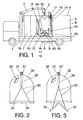
- Figure No. 1 shows a side elevation view of the object of the invention, regarding a mixed vehicle for the collection of waste and washing of igloo type containers.
- Figure No. 2 shows a view of the waste container, specifically a closed glass waste container.
- Figure No. 3 shows a similar view to that shown in figure No. 2, but with the container open.
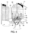
- Figure No. 4 corresponds to a detailed view of the cleaning mechanism and the retaining component of the container doors to facilitate the entry of the cleaning nozzles through the internal area of the container itself.
- the mixed vehicle for the collection of waste and washing of igloo type containers is formed from a chassis (1) provided with a crane jib (2) for the handling and positioning of the container (30), the crane jib having a double hook (3) and there being over the truck chassis (1), a box (4) provided with a side safety door (5) and a deposit for waste (6), that is to incorporate the waste contained inside the container.
- the vehicle is provided with a washing system, configured as a deposit for clean water (7), a set of pumps (8), a foaming station (9), a vertical brush (10), a dome shaped brush (11), a washing bedplate (12), an external rinsing arch (13), an external foaming arch (14) and some internal rinsing heads (15) and (15').
- a washing system configured as a deposit for clean water (7), a set of pumps (8), a foaming station (9), a vertical brush (10), a dome shaped brush (11), a washing bedplate (12), an external rinsing arch (13), an external foaming arch (14) and some internal rinsing heads (15) and (15').
- the vehicle has a waste water evacuation system, consisting of a collector (16), a filtering unit (17), a waste water pump (18), a waste water deposit (19) and in turn is provided with a pressure jet (20) for manual use.
- a waste water evacuation system consisting of a collector (16), a filtering unit (17), a waste water pump (18), a waste water deposit (19) and in turn is provided with a pressure jet (20) for manual use.
- the invention is implemented, as may be seen in figure number 4 with a part (45) provided with two rollers (44) and (44') located over a rotary part (41) which keeps the doors (34) and (34') open, whilst the cleaning heads (15) and (15') act and in turn, permitting the contents to run out.
- the two rings (31) and (31') are destined, one of them to lift the container with the covers closed and the other, to lift the hood, leaving the sluices (34) and (34') located in the lower part, free, producing the opening for the unloading manoeuvre of the container contents.
- the towlines (33) connecting the sluices (34) and (34') with the rings (31) and (31') are located inside.
- the container (30) is manufactured in glass fibre or similar.
- the truck arrives at the destination and by means of the crane jib (3) incorporated over the crane (2), which is provided with a double hook, hooks the two rings (31) and (31') of the container (30) and once hooked, lifts the container (30) until locating it above the waste deposit (6) which has the upper part open.
- the crane jib (3) hooks are automated, so that on pulling one of them, the unloading sluices (34) and (34') are opened, permitting the emptying of the container contents.
- the container (30) Once the container (30) has been unloaded with the sluices (34) and (34') open, it is positioned over the washing bedplate (12) and by means of a vertical movement in a descending direction, it is deposited over it.
- the bedplate (12) is designed such that as the container (30) descends, the unloading sluices close and until ajar, and through this opening, the waste water produced in the washing process is evacuated.
- the crane jib (3) hooks are released and the washing area is hermetically closed by means of the upper side door (5) with the purpose of reducing noise production to a minimum and leakage of waste to the outside.
- the washing area, the brushes (10) and (11), as well as the foaming arch (13) and the rinsing arch (14) are arranged in the washing position by means of conventional hydraulic or pneumatic cylinders, commencing the washing process itself.
- the set of pumps (8) takes water from the clean water deposit (7) and impulses it at a high pressure, dispensing it by means of two rotating heads (15) and (15') throughout the interior of the container (30).
- the supply of the two rotating heads is carried out from the bedplate (12) centre by means of a rotary joint (41), permitting the circular movement or rotation of the entire bedplate (12).
- the external washing consists of external foaming, external brushing and external rinsing.
- foaming of the container on the outside is produced by means of the dispensing arch (14) which projects to the exterior, a chemical cleaning product like soap or detergent, which together with a motor providing rotation to the washing bedplate, over which the container (30) is positioned.
- the arch (14) is fixed and connected to a dosing station which takes the soap or liquid detergent from a deposit and dispenses it as foam.
- the bedplate (12) When the foam is sprayed, the bedplate (12) begins to move and starts to rotate, permitting the container to be covered with foam on its entire external surface and once covered, it is left a while before brushing, with the purpose of allowing the chemical product projected by the arch (14) to act.
- the external brushing is carried out by means of the brushes (10) and (11), that is, the vertical brush and the dome shaped brush, which as may be appreciated is in a vertical position, that is, the (10), whilst the dome shaped brush is displaced remaining attached to the container (30) dome, producing its cleaning in this area unreachable by the vertical brush (10).
- the waste water produced in the washing process is collected in the base of the bedplate and carried to a collector (16) where it is filtered by a filtering unit (17) together with a waste water pump (18), transferring the dirty water (19) to the deposit.
- This deposit stores the water used for its further reuse or for its evacuation in a suitable place.
- the mixed vehicle for the collection of waste and washing of igloo type containers is configured as an appropriate invention for the washing of igloo type containers, using chemical agents, brushes and pressurised water, combining the three mechanisms.
- the vehicle itself is configured as a mixed vehicle simultaneously performing the functions of waste collection and container cleaning, being provided with a special bedplate (12) which permits the container to be fixed, rotating it, accessing to the interior by means of rotating heads (15) and (15') and collecting the waste water in a deposit (19).
- the crane (2) crane jib (3) is provided with a double hook.
Landscapes
- Engineering & Computer Science (AREA)
- Mining & Mineral Resources (AREA)
- Civil Engineering (AREA)
- General Engineering & Computer Science (AREA)
- Structural Engineering (AREA)
- Fluid-Pressure Circuits (AREA)
- Operation Control Of Excavators (AREA)
- Cleaning In General (AREA)
- Cleaning By Liquid Or Steam (AREA)
- Component Parts Of Construction Machinery (AREA)
Applications Claiming Priority (3)
| Application Number | Priority Date | Filing Date | Title |
|---|---|---|---|
| JP2000161468A JP2001336177A (ja) | 2000-05-31 | 2000-05-31 | 建設機械の油圧回路およびアタッチメント緊急駆動方法 |
| JP2000161468 | 2000-05-31 | ||
| PCT/JP2001/004625 WO2001092651A1 (en) | 2000-05-31 | 2001-05-31 | Hydraulic circuit and attachment emergency drive method for construction machinery |
Publications (4)
| Publication Number | Publication Date |
|---|---|
| EP1300519A1 true EP1300519A1 (de) | 2003-04-09 |
| EP1300519A9 EP1300519A9 (de) | 2003-08-06 |
| EP1300519A4 EP1300519A4 (de) | 2009-03-11 |
| EP1300519B1 EP1300519B1 (de) | 2010-12-22 |
Family
ID=18665488
Family Applications (1)
| Application Number | Title | Priority Date | Filing Date |
|---|---|---|---|
| EP01934472A Expired - Lifetime EP1300519B1 (de) | 2000-05-31 | 2001-05-31 | Baumaschine mit einem hydraulischen kreislauf und notbetriebsverfahren eines anbaugerätes. |
Country Status (4)
| Country | Link |
|---|---|
| EP (1) | EP1300519B1 (de) |
| JP (1) | JP2001336177A (de) |
| DE (1) | DE60143698D1 (de) |
| WO (1) | WO2001092651A1 (de) |
Families Citing this family (6)
| Publication number | Priority date | Publication date | Assignee | Title |
|---|---|---|---|---|
| JP4294563B2 (ja) * | 2004-09-10 | 2009-07-15 | 日立建機株式会社 | 作業機械 |
| JP2011226104A (ja) * | 2010-04-16 | 2011-11-10 | Hitachi Constr Mach Co Ltd | 長尺フロントの動力異常停止時降下装置と降下方法 |
| US9085873B2 (en) | 2011-12-23 | 2015-07-21 | Caterpillar Inc. | Hydraulic system for controlling a work implement |
| US9790964B2 (en) | 2014-09-25 | 2017-10-17 | Cnh Industrial America Llc | Hydraulic system |
| US9708796B2 (en) | 2014-09-25 | 2017-07-18 | Cnh Industrial America Llc | Hydraulic valve |
| WO2025063195A1 (ja) * | 2023-09-20 | 2025-03-27 | 日立建機株式会社 | 作業機械 |
Family Cites Families (5)
| Publication number | Priority date | Publication date | Assignee | Title |
|---|---|---|---|---|
| JPS5976659A (ja) | 1982-10-25 | 1984-05-01 | Nippon Kokan Kk <Nkk> | 地金洗浄用バ−ナ− |
| JPH0617885Y2 (ja) * | 1987-04-14 | 1994-05-11 | セイレイ工業株式会社 | バツクホ−における作業機の降下に対する安全装置 |
| JPH0693630A (ja) | 1992-09-11 | 1994-04-05 | Hitachi Constr Mach Co Ltd | 作業機用バケット制御装置 |
| JPH07317713A (ja) * | 1994-05-27 | 1995-12-08 | Yutani Heavy Ind Ltd | 建設機械の油圧回路 |
| JP2000096631A (ja) * | 1998-09-18 | 2000-04-04 | Hitachi Constr Mach Co Ltd | 油圧ショベルの油圧回路 |
-
2000
- 2000-05-31 JP JP2000161468A patent/JP2001336177A/ja active Pending
-
2001
- 2001-05-31 EP EP01934472A patent/EP1300519B1/de not_active Expired - Lifetime
- 2001-05-31 WO PCT/JP2001/004625 patent/WO2001092651A1/ja not_active Ceased
- 2001-05-31 DE DE60143698T patent/DE60143698D1/de not_active Expired - Lifetime
Also Published As
| Publication number | Publication date |
|---|---|
| EP1300519B1 (de) | 2010-12-22 |
| DE60143698D1 (de) | 2011-02-03 |
| JP2001336177A (ja) | 2001-12-07 |
| EP1300519A4 (de) | 2009-03-11 |
| WO2001092651A1 (en) | 2001-12-06 |
| EP1300519A9 (de) | 2003-08-06 |
Similar Documents
| Publication | Publication Date | Title |
|---|---|---|
| EP1302414B1 (de) | Hybriofahrzeuge zum sammeln von abfällen und zum reinigen von igluartigen behältern | |
| US6182673B1 (en) | Dump facility for cassette sewage tanks | |
| KR100947661B1 (ko) | 음식물 쓰레기 용기 세척 시스템 | |
| EP1967467A1 (de) | Vorrichtung zum Waschen eines Müllbehälters und zugehöriges Verfahren | |
| PL186021B1 (pl) | Przemysłowe urządzenie do czyszczenia | |
| EP1300519A1 (de) | Hydraulischer kreislauf und notbetriebsverfahren eines anbaugerätes | |
| US20080105761A1 (en) | Interior and exterior cleaning of waste carts and containers | |
| CN209272012U (zh) | 一种高压喷淋自动清洗机 | |
| CN210280104U (zh) | 化工桶清洗装置 | |
| CN110151074A (zh) | 全自动智能清扫机器人 | |
| JP2009072744A (ja) | フレキシブルコンテナバッグの自動洗浄装置及びその洗浄方法 | |
| CN206624919U (zh) | 原材料清洗机 | |
| EP0705208B1 (de) | Verfahren und vorrichtung zur reinigung von müllbehältern | |
| JP3013902U (ja) | ダストボックス洗浄装置 | |
| KR20230165420A (ko) | 반자동화 통세척장치 | |
| CN211161090U (zh) | 一种清洗装置 | |
| AU728688B2 (en) | Bin washer | |
| CN106967989A (zh) | 一种原材料清洗机及清洗方法 | |
| CN215157927U (zh) | 一种具有微型抓斗的绿色环保垃圾运输车 | |
| CN106807702A (zh) | 一种危险物容器清洗设备和方法 | |
| CN205327025U (zh) | 一种混凝土搅拌车冲洗装置 | |
| JPH0317997Y2 (de) | ||
| CN117483373B (zh) | 粮斗用清洗装置 | |
| CN221414385U (zh) | 粮斗用清洗装置 | |
| SU1664427A1 (ru) | Установка дл мойки внутренней поверхности мусорных контейнеров |
Legal Events
| Date | Code | Title | Description |
|---|---|---|---|
| PUAI | Public reference made under article 153(3) epc to a published international application that has entered the european phase |
Free format text: ORIGINAL CODE: 0009012 |
|
| 17P | Request for examination filed |
Effective date: 20020701 |
|
| AK | Designated contracting states |
Designated state(s): AT BE CH CY DE DK ES FI FR GB GR IE IT LI LU MC NL PT SE TR Kind code of ref document: A1 Designated state(s): AT BE CH CY DE DK ES FI FR GB GR IE IT LI LU MC NL PT SE TR |
|
| RBV | Designated contracting states (corrected) |
Designated state(s): AT BE CH CY DE FR GB IT LI NL |
|
| A4 | Supplementary search report drawn up and despatched |
Effective date: 20090211 |
|
| 17Q | First examination report despatched |
Effective date: 20090904 |
|
| GRAP | Despatch of communication of intention to grant a patent |
Free format text: ORIGINAL CODE: EPIDOSNIGR1 |
|
| RTI1 | Title (correction) |
Free format text: CONSTRUCTION MACINE WITH A HYDRAULIC CIRCUIT AND ATTACHMENT EMERGENCY DRIVE METHOD. |
|
| GRAS | Grant fee paid |
Free format text: ORIGINAL CODE: EPIDOSNIGR3 |
|
| GRAA | (expected) grant |
Free format text: ORIGINAL CODE: 0009210 |
|
| AK | Designated contracting states |
Kind code of ref document: B1 Designated state(s): DE FR GB IT NL |
|
| REG | Reference to a national code |
Ref country code: GB Ref legal event code: FG4D |
|
| REF | Corresponds to: |
Ref document number: 60143698 Country of ref document: DE Date of ref document: 20110203 Kind code of ref document: P |
|
| REG | Reference to a national code |
Ref country code: DE Ref legal event code: R096 Ref document number: 60143698 Country of ref document: DE Effective date: 20110203 |
|
| REG | Reference to a national code |
Ref country code: NL Ref legal event code: T3 |
|
| PGFP | Annual fee paid to national office [announced via postgrant information from national office to epo] |
Ref country code: FR Payment date: 20110607 Year of fee payment: 11 |
|
| PGFP | Annual fee paid to national office [announced via postgrant information from national office to epo] |
Ref country code: GB Payment date: 20110520 Year of fee payment: 11 Ref country code: NL Payment date: 20110523 Year of fee payment: 11 |
|
| PGFP | Annual fee paid to national office [announced via postgrant information from national office to epo] |
Ref country code: IT Payment date: 20110524 Year of fee payment: 11 Ref country code: DE Payment date: 20110520 Year of fee payment: 11 |
|
| PLBE | No opposition filed within time limit |
Free format text: ORIGINAL CODE: 0009261 |
|
| STAA | Information on the status of an ep patent application or granted ep patent |
Free format text: STATUS: NO OPPOSITION FILED WITHIN TIME LIMIT |
|
| 26N | No opposition filed |
Effective date: 20110923 |
|
| REG | Reference to a national code |
Ref country code: DE Ref legal event code: R097 Ref document number: 60143698 Country of ref document: DE Effective date: 20110923 |
|
| REG | Reference to a national code |
Ref country code: NL Ref legal event code: V1 Effective date: 20121201 |
|
| GBPC | Gb: european patent ceased through non-payment of renewal fee |
Effective date: 20120531 |
|
| PG25 | Lapsed in a contracting state [announced via postgrant information from national office to epo] |
Ref country code: IT Free format text: LAPSE BECAUSE OF NON-PAYMENT OF DUE FEES Effective date: 20120531 |
|
| REG | Reference to a national code |
Ref country code: FR Ref legal event code: ST Effective date: 20130131 |
|
| REG | Reference to a national code |
Ref country code: DE Ref legal event code: R119 Ref document number: 60143698 Country of ref document: DE Effective date: 20121201 |
|
| PG25 | Lapsed in a contracting state [announced via postgrant information from national office to epo] |
Ref country code: NL Free format text: LAPSE BECAUSE OF NON-PAYMENT OF DUE FEES Effective date: 20121201 |
|
| PG25 | Lapsed in a contracting state [announced via postgrant information from national office to epo] |
Ref country code: FR Free format text: LAPSE BECAUSE OF NON-PAYMENT OF DUE FEES Effective date: 20120531 Ref country code: GB Free format text: LAPSE BECAUSE OF NON-PAYMENT OF DUE FEES Effective date: 20120531 |
|
| PG25 | Lapsed in a contracting state [announced via postgrant information from national office to epo] |
Ref country code: DE Free format text: LAPSE BECAUSE OF NON-PAYMENT OF DUE FEES Effective date: 20121201 |