EP1300533A1 - Vorhängeschloss mit einem Europäischen Schliesszylinder - Google Patents
Vorhängeschloss mit einem Europäischen Schliesszylinder Download PDFInfo
- Publication number
- EP1300533A1 EP1300533A1 EP02080552A EP02080552A EP1300533A1 EP 1300533 A1 EP1300533 A1 EP 1300533A1 EP 02080552 A EP02080552 A EP 02080552A EP 02080552 A EP02080552 A EP 02080552A EP 1300533 A1 EP1300533 A1 EP 1300533A1
- Authority
- EP
- European Patent Office
- Prior art keywords
- barrel
- padlock
- passage
- bit
- ring
- Prior art date
- Legal status (The legal status is an assumption and is not a legal conclusion. Google has not performed a legal analysis and makes no representation as to the accuracy of the status listed.)
- Withdrawn
Links
- 230000000903 blocking effect Effects 0.000 claims abstract description 5
- 241001272720 Medialuna californiensis Species 0.000 abstract description 2
- 240000008042 Zea mays Species 0.000 description 2
- 238000009434 installation Methods 0.000 description 2
- 230000002093 peripheral effect Effects 0.000 description 1
- 238000004513 sizing Methods 0.000 description 1
- 230000007704 transition Effects 0.000 description 1
Images


Classifications
-
- E—FIXED CONSTRUCTIONS
- E05—LOCKS; KEYS; WINDOW OR DOOR FITTINGS; SAFES
- E05B—LOCKS; ACCESSORIES THEREFOR; HANDCUFFS
- E05B67/00—Padlocks; Details thereof
- E05B67/06—Shackles; Arrangement of the shackle
- E05B67/22—Padlocks with sliding shackles, with or without rotary or pivotal movement
- E05B67/24—Padlocks with sliding shackles, with or without rotary or pivotal movement with built- in cylinder locks
-
- E—FIXED CONSTRUCTIONS
- E05—LOCKS; KEYS; WINDOW OR DOOR FITTINGS; SAFES
- E05B—LOCKS; ACCESSORIES THEREFOR; HANDCUFFS
- E05B63/00—Locks or fastenings with special structural characteristics
- E05B63/0056—Locks with adjustable or exchangeable lock parts
-
- E—FIXED CONSTRUCTIONS
- E05—LOCKS; KEYS; WINDOW OR DOOR FITTINGS; SAFES
- E05B—LOCKS; ACCESSORIES THEREFOR; HANDCUFFS
- E05B15/00—Other details of locks; Parts for engagement by bolts of fastening devices
- E05B15/16—Use of special materials for parts of locks
- E05B15/1614—Use of special materials for parts of locks of hard materials, to prevent drilling
-
- E—FIXED CONSTRUCTIONS
- E05—LOCKS; KEYS; WINDOW OR DOOR FITTINGS; SAFES
- E05B—LOCKS; ACCESSORIES THEREFOR; HANDCUFFS
- E05B67/00—Padlocks; Details thereof
- E05B67/02—Cases
- E05B67/04—Armoured cases
Definitions
- the present invention relates to a padlock designed to receive a half-barrel of European type.
- European type barrels are very frequently used, including in the padlocks in which it is usual to apply them in the form of half-barrels, i.e. barrels in which the key can only be inserted in one end (front).
- Padlocks fitted with a European half-barrel currently on the market are designed to receive only half-barrels whose parameter mentioned above, i.e. the angle of the bit, is linked to the structure of the padlock, so that a half barrel having another dimension cannot be incorporated into it. It's like that in particular a padlock presented on page 105 of a catalog N ° 2/2000 of the Company Iséo Serrature SpA 25055 Pisogne, Italy.
- the invention aims to provide a padlock meeting this need.
- the invention therefore relates to a padlock whose characteristics are defined in claim 1.
- the padlock can receive half-barrels whose angles of deviation of the bit relative to its plane of symmetry, key removed, can be chosen at any value.
- the padlock according to the invention can also have the characteristics such as defined in the subclaims. It can therefore be seen that the invention makes it possible to solve the problem of adapting a half-barrel of European type whatever or its dimensional configuration.
- the invention applies in particular in the case of security installations in buildings where all locks are fitted with the same type of barrels or half-barrels from a given manufacturer.
- the invention allows the manager of the building to add to the installation one or more padlocks according to the invention in which it can then incorporate barrels of the same type which can be actuated by the same types of keys actuating the other locks of the building according to an access hierarchy given.
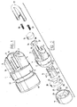
- This padlock comprises a body 1 of quasi-ovoid section which has a base 2 and two columns 3 and 4 extending perpendicularly from one of the faces of the base 2 from the end zones of this face. These columns thus delimit between them a empty 5.
- Each baluster 3 and 4 has a longitudinal groove 6, 7 with a semicircular section, the two grooves facing each other. They are extended in the base 2 by holes respectively 8 and 9 which themselves shrink near the face of the body opposite to columns 3 and 4, the transition being formed by a conical shoulder 10, 11.
- a padlock handle 12 is inserted in the grooves 6, 7 and the holes 8, 9, this handle having a circular section adjusted to that of the grooves and holes.
- the body 1 also has a stepped central bore 13 whose cross section presents the profile of a half European barrel. This hole 13 opens, on the side of the posts 3 and 4 in a recess 14 whose wall 14a is cylindrical.
- a half-barrel of European type 15 is placed with a lateral clearance adjustment in the hole 13, the latter being closed on the side of the columns 3 and 4 by a plug 16 which is adjusted there by force.
- This plug 16 has internally a cavity 16a, the transverse profile is that of a European half-barrel.
- the body 1 has a peripheral clearance 17 on which is fitted the skirt 18 of a hat 19, covering the body 1 on the side opposite to the balusters 3 and 4.
- This cap 19 has a quasi-ovoid shape like the body 1 with a section equivalent. It has two threaded blind holes 20 and 21 extending respectively in alignment with holes 8 and 9 by extending the passages they form respectively in the body 1.
- the cap 19 also has a central bore 22 in extension of the bore 13 of the body 1 and in which extends part of the half-barrel 15.
- this bore 22 On the side opposite the body 1, this bore 22 has a conical inlet 23 and a shoulder 24 against which comes from inside rest an anti-piercing washer 25 made of a material extremely resistant such as carbide, this washer being also used to serve supporting the barrel 15.
- the padlock receives a half barrel 15A having a length equivalent to the upper value of said range.
- a plurality of shims 26 which are arranged one on the others in the cavity of the hat 19 delimited by the skirt 18.
- Each of these shims is formed by a plate of quasi-ovoid shape pierced with two holes 27, 28 intended for coincide with the threaded holes 20, 21 and an opening 29 through which can extend the half-barrel 15 (see FIG. 7).
- the half-barrels on the market in a range of lengths increasing per millimeter, it is advantageous to provide for the padlock according to the invention a set of such plates all having a thickness of 1 mm. In this way, the user can easily adapt the length of the half-barrel himself. which it has in the padlock to be equipped by choosing the number of shims required.
- the cap 19 is attached to the body 1 by means of two screws 30, 31 passed through holes 8, 9 of the body and, where appropriate, through holes 27, 28 of one or several wedges 26 depending on the length of the half-barrel used, then screwed into the threaded holes 20 and 21 of the cap 19.
- the screws 30, 31 are only accessible when the handle 12 is released from the body 1, that is to say when the padlock is open. A no one who does not have the appropriate key can therefore separate hat 19 from body 1.
- the half-barrel 15 has a known manner, of a bit 32 which can make a complete turn around the axis of the cylindrical part of the body of the half-barrel, when the key (not shown) is engaged therein.
- the bit 32 disappears in the profile of the half-barrel, its part end 32a then being placed in a notch 33 formed in the body of the half-barrel 15.
- the cylindrical wall 14a (FIG. 5) of the clearance 14 has a diameter equal to the circle described by the end face 32a of the bit 32 during its movement circular.
- the wall 14a of the clearance 14 is provided with a first lateral cell 14b which extends the bore 13.
- a second cell 14c is also provided in this wall 14a which makes communicate clearance 14 with hole 8.
- the padlock according to the invention also comprises a locking ring 34.
- This ring has a slot 35 whose width is slightly greater than that of the part end of the bit 32. Its axial dimension is slightly less than the width of the notch 33 in the body of the half-barrel 15, while the diameter of its opening 36 is adapted to that of the section of the cylindrical part of the half-barrel 15.
- the surface outside of the locking ring 34 is rounded and its largest diameter is slightly smaller than the clearance diameter 14.
- this ring 34 can engage on the half-barrel 15, when the bit 32 is erased in the body of the half-barrel and that it can accompany the rotation of the bit 32, when the key is turned in the half-barrel 15.
- the ring has this ability to support whatever the angle from which the bit 32 when the half-barrel 15 is in the open configuration and the key can be withdrawn.
- the ring 34 therefore adapts to any half-barrel whatever the angle of deflection of its bit.
- the ring 34 is also provided with an external notch 37 in a half moon, the shape is adapted to that of the section of the handle 12. It will also be noted that this the latter is provided with a lateral notch 38 of a shape adapted to the periphery of the ring 34.
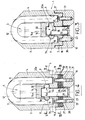
- Figure 5 shows the padlock according to the invention in its open position.
- the notch 37 of the ring 34 is located opposite the handle 12 so that it can be removed from the padlock.
- the bit 32 is then moved at an angle relative to at its retracted position which can be the angle ⁇ indicated in FIG. 5.
- the key cannot be removed from the barrel.
- this is not a problem for a convenient use of the padlock.
- the padlock is in its closed configuration.
- the ring 34 has been turned by the bit 32 actuated by the key (in the example of 90 °) relative to the configuration of FIG. 5.
- the handle 12 is then blocked by the ring of blocking 34 which penetrates through a portion of its periphery into the notch 38 of this handle 12 crossing the cell 14b.
- the bit 32 is then removed from the retracted position with an angle ⁇ less than 45 °, this angle ⁇ having been chosen as being the one corresponding to the possibility of removing the key.
- the arrangement according to the invention makes it possible to adapt to a half-barrel having any angle of deviation between the retracted position of bit 32 and the position in which the key can be removed from the half-barrel 15.
- Figures 5 and 6 in particular show that the padlock according to the invention has a protected arrangement of the means fixing the half-barrel 15 in the body 1.
- an orifice 39 is drilled approximately tangentially to the wall 14a of the clearance cylindrical 14. This orifice passes through the hole 9 in which the handle is positioned 12.
- a screw locking 40 is screwed into a threaded hole 41 provided in a well-known manner in the half-barrel 15. Access to screw 40 is prohibited when the handle 12 is in place and the padlock Locked.
- Figures 8 and 9 show a variant of the padlock according to the invention in the in which case a straight locking rod 12A is provided instead of the handle 12. in this case it it is only necessary to provide aligned holes on one side to accommodate a single screw attachment 30A, the rod being held at the opposite end in a branch 42 forming part of body 1A of the padlock.
Landscapes
- Engineering & Computer Science (AREA)
- Structural Engineering (AREA)
- Closures For Containers (AREA)
- Switch Cases, Indication, And Locking (AREA)
Applications Claiming Priority (3)
| Application Number | Priority Date | Filing Date | Title |
|---|---|---|---|
| FR0106060A FR2824352B1 (fr) | 2001-05-07 | 2001-05-07 | Cadenas comportant un demi-barillet de type europeen |
| FR0106060 | 2001-05-07 | ||
| EP02291150A EP1256675A1 (de) | 2001-05-07 | 2002-05-07 | Vorhängeschloss mit einem Europäischen Schliesszylinder |
Related Parent Applications (1)
| Application Number | Title | Priority Date | Filing Date |
|---|---|---|---|
| EP02291150A Division EP1256675A1 (de) | 2001-05-07 | 2002-05-07 | Vorhängeschloss mit einem Europäischen Schliesszylinder |
Publications (1)
| Publication Number | Publication Date |
|---|---|
| EP1300533A1 true EP1300533A1 (de) | 2003-04-09 |
Family
ID=8863036
Family Applications (2)
| Application Number | Title | Priority Date | Filing Date |
|---|---|---|---|
| EP02080552A Withdrawn EP1300533A1 (de) | 2001-05-07 | 2002-05-07 | Vorhängeschloss mit einem Europäischen Schliesszylinder |
| EP02291150A Withdrawn EP1256675A1 (de) | 2001-05-07 | 2002-05-07 | Vorhängeschloss mit einem Europäischen Schliesszylinder |
Family Applications After (1)
| Application Number | Title | Priority Date | Filing Date |
|---|---|---|---|
| EP02291150A Withdrawn EP1256675A1 (de) | 2001-05-07 | 2002-05-07 | Vorhängeschloss mit einem Europäischen Schliesszylinder |
Country Status (2)
| Country | Link |
|---|---|
| EP (2) | EP1300533A1 (de) |
| FR (1) | FR2824352B1 (de) |
Cited By (2)
| Publication number | Priority date | Publication date | Assignee | Title |
|---|---|---|---|---|
| DE102005026930B4 (de) * | 2004-09-20 | 2009-05-07 | Schloßsicherungen Gera GmbH | Vorhangschloss |
| CN102677995A (zh) * | 2012-04-05 | 2012-09-19 | 余义伦 | 一种高安全锁及钥匙 |
Families Citing this family (1)
| Publication number | Priority date | Publication date | Assignee | Title |
|---|---|---|---|---|
| EP1460212B1 (de) * | 2003-03-05 | 2010-05-05 | ISEO Deutschland GmbH | Vorhangschloss |
Citations (3)
| Publication number | Priority date | Publication date | Assignee | Title |
|---|---|---|---|---|
| GB2270951A (en) * | 1992-09-03 | 1994-03-30 | Mul T Lock Ltd | Padlock assembly |
| EP0927802A1 (de) * | 1997-12-17 | 1999-07-07 | Waterson Chen | Verriegelungsvorrichtung |
| EP1001121A1 (de) * | 1998-11-11 | 2000-05-17 | Larry Edward Houghton | Vorhängeschloss mit Drehaktion |
Family Cites Families (1)
| Publication number | Priority date | Publication date | Assignee | Title |
|---|---|---|---|---|
| US5921123A (en) * | 1997-04-18 | 1999-07-13 | Abus August Bremicker Soehne Ag | Rekeyable padlock |
-
2001
- 2001-05-07 FR FR0106060A patent/FR2824352B1/fr not_active Expired - Fee Related
-
2002
- 2002-05-07 EP EP02080552A patent/EP1300533A1/de not_active Withdrawn
- 2002-05-07 EP EP02291150A patent/EP1256675A1/de not_active Withdrawn
Patent Citations (3)
| Publication number | Priority date | Publication date | Assignee | Title |
|---|---|---|---|---|
| GB2270951A (en) * | 1992-09-03 | 1994-03-30 | Mul T Lock Ltd | Padlock assembly |
| EP0927802A1 (de) * | 1997-12-17 | 1999-07-07 | Waterson Chen | Verriegelungsvorrichtung |
| EP1001121A1 (de) * | 1998-11-11 | 2000-05-17 | Larry Edward Houghton | Vorhängeschloss mit Drehaktion |
Cited By (3)
| Publication number | Priority date | Publication date | Assignee | Title |
|---|---|---|---|---|
| DE102005026930B4 (de) * | 2004-09-20 | 2009-05-07 | Schloßsicherungen Gera GmbH | Vorhangschloss |
| CN102677995A (zh) * | 2012-04-05 | 2012-09-19 | 余义伦 | 一种高安全锁及钥匙 |
| CN102677995B (zh) * | 2012-04-05 | 2014-08-20 | 余义伦 | 一种高安全锁及钥匙 |
Also Published As
| Publication number | Publication date |
|---|---|
| FR2824352B1 (fr) | 2003-12-12 |
| FR2824352A1 (fr) | 2002-11-08 |
| EP1256675A1 (de) | 2002-11-13 |
Similar Documents
| Publication | Publication Date | Title |
|---|---|---|
| EP0963498B1 (de) | Verschlussvorrichtung für eine tür | |
| FR2504180A1 (fr) | Serrure a pene dormant | |
| FR2704525A1 (fr) | Ensemble de verrouillage de bouchon. | |
| EP1300533A1 (de) | Vorhängeschloss mit einem Europäischen Schliesszylinder | |
| FR2686643A1 (fr) | Serrures pour fenetre et a levier ayant un cadenas. | |
| FR2561291A1 (fr) | Dispositif de protection d'entree de cle de serrure | |
| FR2824353A1 (fr) | Cadenas comportant un demi-barillet de type europeen | |
| EP3592995B1 (de) | Sicherheitsschraubenanordnung und betriebsschlüssel dafür | |
| EP0606196B1 (de) | Schliessvorrichtung | |
| FR2734305A1 (fr) | Gond composite | |
| EP0874114B1 (de) | Zylindersicherheitsschloss mit erhöhtem Einbruchswiderstand | |
| BE1010936A3 (fr) | Dispositif de fermeture pour porte. | |
| FR2610352A1 (fr) | Plaque pour poignee de porte | |
| EP0902138A1 (de) | Zylinderschloss und Schlüssel dafür | |
| CH677517A5 (en) | Security lock - has tilting or deforming element which fits into aperture in bolt slide plate when any attempt is made to tamper with lock | |
| FR2784413A1 (fr) | Dispositif de protection reglable de cylindre de serrure | |
| FR2666369A1 (fr) | Ferrure pour une fenetre, une porte, ou similaire. | |
| FR2772062A1 (fr) | Verrou de surete a barillet normalise | |
| FR2643690A1 (en) | Screw-type fixing device, and support assemblies for a television set including this device | |
| FR2710094A1 (fr) | Système de fixation d'un bouton sur une face d'un panneau de porte, notamment une porte palière. | |
| CA1206947A (fr) | Dispositif de verrouillage de vannes | |
| BE1011694A7 (fr) | Dispositif de fermeture pour porte. | |
| EP0874115A1 (de) | Zylindersicherheitsschloss mit erhöhtem Einbruchswiderstand | |
| FR2777125A1 (fr) | Dispositif de fermeture a securite, notamment pour coffret, armoire ou autre enveloppe electrique | |
| FR3003886A1 (fr) | Dispositif d’entrebaillement |
Legal Events
| Date | Code | Title | Description |
|---|---|---|---|
| PUAI | Public reference made under article 153(3) epc to a published international application that has entered the european phase |
Free format text: ORIGINAL CODE: 0009012 |
|
| AC | Divisional application: reference to earlier application |
Ref document number: 1256675 Country of ref document: EP Kind code of ref document: P |
|
| AK | Designated contracting states |
Kind code of ref document: A1 Designated state(s): AT BE CH CY DE DK ES FI FR GB GR IE IT LI LU MC NL PT SE TR Designated state(s): AT BE CH CY DE DK ES FI FR GB GR IE IT LI LU MC NL PT SE TR |
|
| AX | Request for extension of the european patent |
Extension state: AL LT LV MK RO |
|
| 17P | Request for examination filed |
Effective date: 20030912 |
|
| AKX | Designation fees paid |
Designated state(s): AT BE CH CY DE DK ES FI FR GB GR IE IT LI LU MC NL PT SE TR |
|
| GRAP | Despatch of communication of intention to grant a patent |
Free format text: ORIGINAL CODE: EPIDOSNIGR1 |
|
| STAA | Information on the status of an ep patent application or granted ep patent |
Free format text: STATUS: THE APPLICATION IS DEEMED TO BE WITHDRAWN |
|
| 18D | Application deemed to be withdrawn |
Effective date: 20041103 |