EP3592995B1 - Sicherheitsschraubenanordnung und betriebsschlüssel dafür - Google Patents
Sicherheitsschraubenanordnung und betriebsschlüssel dafür Download PDFInfo
- Publication number
- EP3592995B1 EP3592995B1 EP18712947.3A EP18712947A EP3592995B1 EP 3592995 B1 EP3592995 B1 EP 3592995B1 EP 18712947 A EP18712947 A EP 18712947A EP 3592995 B1 EP3592995 B1 EP 3592995B1
- Authority
- EP
- European Patent Office
- Prior art keywords
- head
- rotor
- ring
- screw
- assembly according
- Prior art date
- Legal status (The legal status is an assumption and is not a legal conclusion. Google has not performed a legal analysis and makes no representation as to the accuracy of the status listed.)
- Active
Links
Images


Classifications
-
- B—PERFORMING OPERATIONS; TRANSPORTING
- B25—HAND TOOLS; PORTABLE POWER-DRIVEN TOOLS; MANIPULATORS
- B25B—TOOLS OR BENCH DEVICES NOT OTHERWISE PROVIDED FOR, FOR FASTENING, CONNECTING, DISENGAGING, OR HOLDING
- B25B13/00—Spanners; Wrenches
- B25B13/48—Spanners; Wrenches for special purposes
- B25B13/485—Spanners; Wrenches for special purposes for theft-proof screws, bolts or nuts
-
- F—MECHANICAL ENGINEERING; LIGHTING; HEATING; WEAPONS; BLASTING
- F16—ENGINEERING ELEMENTS AND UNITS; GENERAL MEASURES FOR PRODUCING AND MAINTAINING EFFECTIVE FUNCTIONING OF MACHINES OR INSTALLATIONS; THERMAL INSULATION IN GENERAL
- F16B—DEVICES FOR FASTENING OR SECURING CONSTRUCTIONAL ELEMENTS OR MACHINE PARTS TOGETHER, e.g. NAILS, BOLTS, CIRCLIPS, CLAMPS, CLIPS OR WEDGES; JOINTS OR JOINTING
- F16B23/00—Specially shaped nuts or heads of bolts or screws for rotations by a tool
-
- F—MECHANICAL ENGINEERING; LIGHTING; HEATING; WEAPONS; BLASTING
- F16—ENGINEERING ELEMENTS AND UNITS; GENERAL MEASURES FOR PRODUCING AND MAINTAINING EFFECTIVE FUNCTIONING OF MACHINES OR INSTALLATIONS; THERMAL INSULATION IN GENERAL
- F16B—DEVICES FOR FASTENING OR SECURING CONSTRUCTIONAL ELEMENTS OR MACHINE PARTS TOGETHER, e.g. NAILS, BOLTS, CIRCLIPS, CLAMPS, CLIPS OR WEDGES; JOINTS OR JOINTING
- F16B41/00—Measures against loss of bolts, nuts, or pins; Measures against unauthorised operation of bolts, nuts or pins
- F16B41/005—Measures against unauthorised operation of bolts, nuts or pins
-
- F—MECHANICAL ENGINEERING; LIGHTING; HEATING; WEAPONS; BLASTING
- F16—ENGINEERING ELEMENTS AND UNITS; GENERAL MEASURES FOR PRODUCING AND MAINTAINING EFFECTIVE FUNCTIONING OF MACHINES OR INSTALLATIONS; THERMAL INSULATION IN GENERAL
- F16B—DEVICES FOR FASTENING OR SECURING CONSTRUCTIONAL ELEMENTS OR MACHINE PARTS TOGETHER, e.g. NAILS, BOLTS, CIRCLIPS, CLAMPS, CLIPS OR WEDGES; JOINTS OR JOINTING
- F16B2200/00—Constructional details of connections not covered for in other groups of this subclass
- F16B2200/83—Use of a magnetic material
Definitions
- the present invention relates to a safety screw assembly and its operating key.
- screw is meant here a mechanical connecting member between at least two elements.
- a screw made of metal or another rigid material, is generally elongated and provided, over at least part of its length, with a thread and, at one end, with a part called the head and allowing the maneuver of the screw.
- Such a screw is adapted to cooperate with a thread complementary to its thread when the screw is introduced by screwing, therefore by a rotational movement associated with a translation, into the threaded housing of complementary shape.
- Such a characteristic is, in many cases, sought in order to facilitate maintenance or dismantling of the elements.
- Such a restriction is generally motivated by protection and/or security needs, either of the user or of the property on which the screw is located, or of both.
- screws for locking a vehicle wheel for holding in the closed or open position a connecting cover between two elements of a machine tool, for closing a cover or access door to a given zone, whether this zone is a volume accessible to living beings, humans or animals, or whether this zone is an interior volume of an object within the meaning wide.
- this zone is a volume accessible to living beings, humans or animals, or whether this zone is an interior volume of an object within the meaning wide.
- FR-A-2 728 318 discloses such a type of bolt.
- WO-A-2012 040 800 safety bolts where any attempt to unscrew causes part of the head to break, this part then becoming free to rotate and preventing any transmission of the rotational movement, in screwing or unscrewing, to the entire bolt.
- WO-A-2012 148050 Where WO-A-2005 012 737 protection devices, of the cap type, positioned on the head of the screw and preventing the loosening and/or theft of the nut.
- the invention aims to provide a safety screw assembly and its operating key, easy to use and suitable for allowing rapid installation and removal of the screw, without this operation being carried out by an unauthorized person. is possible.
- the subject of the invention is a safety screw assembly and its operating key according to claim 1, comprising said screw formed of a body and a head, the head being movable between a first position where it is integral in rotation with the body and a second position where it is free in rotation, the head being provided on one face with an opening or with a relief of a shape complementary to a relief or an imprint formed on a part of the said key of maneuver, where one end of the body of the screw comprises a first part called the stator, and a second part, movable in rotation, called the rotor, the head of the screw defining a housing for receiving the rotor, and where the assembly comprises a member of securing, movable in translation, said member being movable between a first securing position, called idle, where the head is free in rotation and the rotor and the stator are integral in rotation and a second position, called blocked, where at least the head and the e stator are fixed in rotation and where the key is provided with at least one member
- the figure 1 illustrates a screw 1 belonging to a screw and wrench assembly in accordance with one embodiment of the invention.
- the screw 1 comprises a cylindrical body with a circular base and threaded 2.
- the length, the diameter and the thread pitch of the body 2 are preferably chosen from the standardized data for the screws. Alternatively, these data are specific and adapted to the use of screw 1.
- a screw head 3 cylindrical with a circular base, equips one end 4 of the body 2.
- the end 4 constitutes the stator of the screw 1.
- the outer face 5 of the head 3 is provided with a through opening 6.
- the opening 6 is pentagonal with rectilinear walls. As a variant not shown, it is of another shape, for example hexagonal or octagonal with curved walls.
- a bottom 7 closes off part of the opening 6, as can be seen in figure 1 .
- Bottom 7 is independent of head 3. It constitutes a rotor 25.
- Bottom 7 is flat and made of a material permeable to magnetic waves. In this case it is metal.
- a lug 8 is fixed perpendicularly to the bottom 7, close to the periphery of the latter. As emerges from the figure 8 , the lug 8 is cylindrical in shape and positioned in the center of a well 80, so that its top is coplanar with the bottom 7. In another embodiment, the bottom 7 is provided with more than one lug and /or different shapes. For example, one or two lugs 8 extend perpendicularly from the bottom 7.
- the figure 2 illustrates an operating key 9 according to one embodiment.
- Key 9 is cylindrical in shape.
- it is made of a metal insensitive to corrosion, for example made of stainless steel.
- it is made of polymers or of a composite material based on metal and polymer.
- One end of the key 9 is formed by a relief 10 of a shape complementary to the shape of the opening 6 of the head 3.
- the relief 10 is pentagonal.
- the relief 10 has dimensions such that they allow, by rotation of the key 9 around its longitudinal axis A9, to turn the head 3 of the screw in one direction or the other. , according to the double arrow F9.
- the relief 10 allows screwing or unscrewing of the screw 1.
- the key 9 makes it possible to carry out a tightening with a given and defined tightening torque for each screw and key assembly, according to the needs.
- the opposite end of the key 9 to the relief 10 is formed by a relief 11, cylindrical with a circular base and a flat and circular top.
- the dimensions of the relief 11 are adapted to allow the introduction of the relief 11 into the opening 6 but without the rotation of the relief 11 causing the rotation of the head 3.
- the figure 9 illustrates another embodiment of an operating key 90 in accordance with the invention.
- Key 90 is also cylindrical in shape.
- the functionally identical elements between the keys 9; 90 have the same references, multiplied by a factor of ten.
- the end relief 100 of the key 90 is identical to the end relief 10 of the key 9.
- the relief 110 of the key 90 is identical to the relief 11 of the key 9.
- the top 120 of the relief 110 is flat and circular. It is equipped with a hollow relief 13 of a shape complementary to that of the lug 8 and the well 80 located on the bottom 7.
- the top 12 of the relief 11 is similar to the top 120 of the relief 110. It is also provided with a hollow relief, similar to relief 13 and not visible in the various figures.
- At least one cylindrical magnet is housed inside the relief 11; 110 therefore behind the flat metal top 12; 120.
- a magnet can be monopolar or multipolar. Depending on the complexity of the desired coding, several magnets will be used, multipolar preference. In this case, according to an advantageous embodiment of the invention, there are three multipolar magnets. This term designates magnets made from several parts, here cylinder quarters, which alternate their polarities. Thus, one end of such a magnet has a given alternation of south and north poles, with a given angular orientation. Such an arrangement is known per se from EP-A-1 601 848 .
- the keys 9; 90 of two different embodiments of the invention have cylindrical shapes with ends 10; 100 and 11; 110 identical. They differ by their central parts also called main body.
- the main body 14 of the key 9 is formed of two coaxial sleeves 15, 16.
- the sleeve 15 comprises a zone 150 of external diameter greater than that of the other part 151 constituting the sleeve 15.
- the zone 150 thus forms a ring of gripping of the sleeve 15.
- the zone 150 makes it possible, by a translational movement according to the double arrow F, to bring the end 11 into or out of the sleeve 15, more particularly in the part 151.
- the protection of the end relief 11 and, more precisely, of its top 12 is ensured.
- the flat top 12 must be protected against any shock and/or deformation in order to guarantee the integrity of the magnets housed in the end 11 and to allow the connection of the lug 8 with the lug 13. It is understood that, to allow the passage of the magnetic radiation emitted or received by the magnets inserted in the relief 11, the top 12 is of low thickness, which, de facto, reduces its re mechanical resistance to shocks and deformations.
- a protective cap for example screwable or clippable, is provided to protect the relief 11 or 110.
- the sleeve 16 whose external diameter is close to the external diameter of the part 150, ensures the grip and the maneuver of the key 9 during the screwing or unscrewing operations of the screw 1.
- the key 90 comprises a main body 17 comprising an outer sleeve 170.
- the sleeve 170 receives an internal sleeve, coaxial 171 provided with the end relief 110.
- the sleeve 171 is screwed, or in a variant slides, into the sleeve 170. In this way, a helical or translational movement oriented in a direction parallel to the longitudinal axis A90 of the key 90 ensures the entry and exit of the end relief 110 of the sleeve 171.
- the picture 3 illustrates the body 2 of the screw alone, without the head 3.
- the non-threaded end 4 of the body 2 is cylindrical in shape, with a circular and open base.
- the end 4 comprises at least one, advantageously three, housings 18 in the form of cylindrical wells with a circular base.
- the wells 18 are adapted to receive pistons, movable in translation along a direction parallel to the longitudinal axis A2 of the body 2. For greater readability, the pistons are not visible to the picture 3 .
- the housings 18, together with the pistons and the end 4, define a stator.
- the housings 18 have their access openings coplanar with the bottom 19 of the end 4.
- the bottom 19 is flat and circular.
- the cylindrical outer wall 20 of the end 4 is provided with at least one, advantageously five, rectangular notches 21 made from the free upper edge of the wall 20.
- the notches 21 are regularly distributed over the wall 20.
- the interior volume of end 4 is defined by two coaxial cylinder portions of different diameters.
- the portion 22, of smaller diameter, extends from the bottom 19 over approximately half the height of the wall 20.
- Portion 23 is the terminal portion of end 4 and it extends portion 22 outwards. Thus, the portion 23 of larger diameter defines access to the volume of the end 4, therefore to the stator as defined above.
- An annular groove 24 is made on the outer face of the wall 20, substantially at the level of the junction zone between the parts 22 and 23.
- the end 4 forms a housing having an access opening with a diameter greater than that of the bottom of the housing.
- the end 4 is adapted to receive a piece of complementary shape 25 called the rotor.
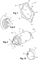
- This rotor 25 is illustrated in figures 5 and 6 . It comprises a cylindrical portion with a circular base 26 whose external diameter is smaller than the internal diameter of the portion 22, so that the portion 26, once introduced into the portion 22, is maintained in the latter while being free to rotate. Portion 26 is provided with at least one, advantageously three, wells 27.
- Wells 27 are cylindrical with a circular base and each provided with a longitudinal groove 28. Wells 27 are adapted to receive, with a given angular position, magnets, multipolar or not, not illustrated and known per se. Each magnet is immobilized in rotation in its well 27 by a relief provided on the magnet and introduced into the groove 28.
- the rotor 25 comprises a second portion 29, also cylindrical with a circular base.
- the bottom 7 of the portion 29 is common with the closed end of the portion 26 and therefore defines the bottom of the wells 27.
- the bottom 7 is visible when the rotor 25 is in place in the end 4 and the head 3 caps the rotor 25.
- the bottom 7 of the portion 29 of the rotor 25 forms a flat, visible interface between the outside and the magnets of the rotor, as shown in figure 1 .
- the outer face of the wall 30 of the portion 29 is equipped with a helical ramp 31.
- the ramp 31 comprises, at the top and bottom dead centers, stops 32.
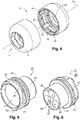
- the figure 4 illustrates the head 3 alone, from two viewing angles.
- the head 3 is in the form of a cylindrical cap with a circular base, completely open at one end and provided with an opening 6 formed on the opposite face 5 of the head 3.
- the internal face 33 of the head 3 is provided with at least one, advantageously five, longitudinal grooves 34, here of rectangular cross-section, arranged parallel to the longitudinal axis A3 of the head 3.
- An annular groove 35 is formed on the face 33 of the head 3 and located at one end of the grooves 34 , in the vicinity of the bottom of the head 3, therefore of the face 5.
- Another annular groove 36 is provided on the inner face 33.
- This groove 36 is parallel to the groove 35 and intended to partially receive a connecting rod or clips when this rod or clips is introduced, also partially, into the annular groove 24 of the wall 20 of the end 4 of the body when the head 3 is in position on the body 2. Thus, any dismantling of the head 3 is prohibited while allowing its rotation relative to the co rps 2.
- the figure 7 illustrates an embodiment of a rotation securing member 37 of the rotor 25 with the head 3.
- the member 37 is configured as a flat ring.
- At least one, advantageously five legs, here rectangular, 38 extend outwards from the solid part 39 of the ring 37.
- the legs 38 are coplanar with the solid part 39.
- Two reliefs 40, also coplanar with the solid part 39, extend from the latter in the direction of the central opening of the ring 37.
- the legs 38 are of shapes and dimensions complementary to those of the grooves 34.
- the figures 11 to 17 illustrate the various positions of the constituent elements of a screw 1 as well as the operation of the screw using a key according to one embodiment of the invention.
- the figures 11 and 12 represent the screw 1 in section along two longitudinal section planes forming between them an angle close to 120°, in a configuration where the head 3 is said to be rotationally idle.
- the head 3, mounted on the body 2 is free to rotate around the longitudinal axes A2 and A3 combined, while the body 2 is stationary in rotation.
- the rotor 25 is fixed in rotation to the body 2, more particularly to the end 4.
- the internal face 33 of the head 3 is not fixed in rotation to the wall 20 of the end 4 of the body 2 while being connected to the latter.
- the head 3 is crazy in rotation but it is secured to the body 2 and it cannot be detached from the latter.
- This configuration is obtained by mounting the ring 37 between the head 3 and the rotor 25.
- the ring 37 is mounted around the helical ramp 31 of the rotor 25, the latter being positioned in the end 4, having the portion 26 of rotor 25 provided with magnets facing wells 18, in part 22 of end 4.
- the rotor 25 is held in position in the end 4.
- a seal is introduced into an annular groove 42, visible at figure 6 , and made on the outer face of part 29.
- the lugs 38 extend outwards from the end 4 passing through the notches 21.
- the translational movement generated by the helical ramp 31 of the rotor 35 is limited by the stops 32 of the rotor 25 when they are in contact with the reliefs 40 of the ring 37.
- the displacement of the ring 37 is limited by the rotation of the rotor 25, rotation limited to approximately a quarter turn by the contact between the reliefs 40 of the ring 37 on the stops 32 of the ramp 31.
- the tabs 38 inserted in the notches 21 ensure the connection in rotation of the ring 37 and the end 4 of the body 2. In other words, the ring 37 provides a connection between the head 3 and the body 2.
- the ring 37 when it is in the high position on the ramp 31 is positioned at the bottom of the head 3, at the level of the groove 35.
- the legs 38 have moved in translation, in a guided manner, in the notches 21 and the grooves 34 of the head 3.
- the lugs 38 are de facto inserted into the groove 35. It is understood that this translational movement of the ring 37 results of the rotational movement of the rotor 25.
- the lugs 38 in position in the groove 35 allow the free rotation of the head 3 relative to the body 2 of the screw 1. Insofar as the opening 6 made in the head 3 allows the screwing or unscrewing of the screw 1 , it is not possible to perform these operations: only the head 3 is rotated and not the rest of the screw 1. This so-called crazy configuration is therefore a secure configuration, no modification of the position of the screw 1, tightening or not, of elements not being possible.
- the holding in position of the ring 37 in the groove 35 is optimized by springs 41 occupying the bottom of the head 3 in one direction of thrust and, in the opposite direction of thrust, by the rotor 25 itself.
- springs not shown, inserted in the wells 18 push the pistons in the direction of the rotor 25.
- the ends of the pistons, under the action of the springs, are partially introduced into the housings 27 of the rotor 25 which receive the magnets.
- the rotor 25 is locked in rotation by the pistons by relative to the rest of the body 2.
- the ring 37 being in position in the groove 35, only the head 3 can freely turn in rotation around the axes A2, A3 combined.
- This configuration also called disengaged, also corresponds to a so-called coding configuration of the magnets of the rotor 25. Indeed, the magnets are stationary in rotation and in translation.
- the figures 16 and 17 illustrate this maneuver with a key 90, it being understood that the maneuver is identical with a key 9.
- the end 120 is introduced through the opening 6 and positioned so that the lugs 13 and 8 are in contact. In this way, the magnets of the rotor 25 are aligned with those of the relief 120. In other words, the positioning is guided, the lugs 13 and 8 serving as polarizers.
- a spring 43 pushes the lug 13 back onto the lug 8, thus securing the positioning of the relief 120 on the bottom 7 of the rotor 25.
- the polarities of same sign, north or south, magnets of the relief 120 and of the rotor 25 are opposite.
- the magnets of the rotor 25 are movable in translation in the housings 27, this translation being guided by the grooves 28 which prevent the magnets from pivoting, the magnets of the rotor 25 move in the direction of the stator, namely in the direction of the wells 18 of the end 4. In this way, the pistons are pushed back to the bottom of the wells 18. The pistons are no longer partially introduced into the housings 27 and therefore no longer block the rotor 25 in rotation.
- the securing member in the form of a ring 37 ensures a connection between the stator, formed by the end 4 and the pistons, and the head 3, these elements being immobile with respect to each other. other. It is then possible for the user, with the relief 10 or 100 of the key 9 or 90 to screw or unscrew the screw 1.
- Such an assembly finds, for example, its application for securing the closing of an access cover to control and/or operating elements of a machine tool, an automatic barrier, a terminal access, a parking meter, a traffic light mast, a lamppost, an automatic distributor of products or services, mailboxes, safety or electrical boxes or others.
- a key allows the operation of several screws having the same magnetic coding.
- a key can receive reliefs 11; 110, removable or not, allowing the operation of several screws or sets of screws with different codings.
- the key is provided with more than one relief receiving magnets, for example a set of reliefs each equipped with magnets coding for a given series of screws.
- the operation of the screw is performed by a tool known per se, the configuration of the opening of the head corresponding to a standardized geometric shape.
- the opening of the head is configured to receive only the relief equipped with the magnets.
- the screwing or unscrewing of the screw being carried out by a key in engagement with the outside of the head, the latter being, for example, pentagonal exterior shape.
- the relief ensuring the operation of the head of the screw is hollow and receives, in its internal volume, the relief equipped with magnets.
- the latter is movable in translation, for example by sliding, in the first relief.
Landscapes
- Engineering & Computer Science (AREA)
- General Engineering & Computer Science (AREA)
- Mechanical Engineering (AREA)
- Details Of Spanners, Wrenches, And Screw Drivers And Accessories (AREA)
- Transmission Devices (AREA)
- Burglar Alarm Systems (AREA)
- Lock And Its Accessories (AREA)
Claims (11)
- Sicherheitsschraubenanordnung (1) und ihr Betätigungsschlüssel (9; 90), der die Schraube (1) umfasst, die aus einem Körper (2) und einem Kopf (3) gebildet ist, wobei der Kopf (3) zwischen einer ersten Position, in der er drehfest mit dem Körper (2) verbunden ist, und einer zweiten Position, in der er in Drehung frei ist, beweglich ist, wobei der Kopf (3) auf einer Fläche (5) mit einer Öffnung (6) oder mit einem Relief mit komplementärer Form zu einem/einer auf einem Teil des Betätigungsschlüssels (9; 90) eingerichteten Relief (10; 100) oder Prägung versehen ist, wobei ein Ende (4) des Körpers (2) der Schraube (1) einen ersten Teil (4, 18, 20, 21, 22, 23), Stator genannt, und einen zweiten Teil (25), der in Drehung beweglich ist, Rotor genannt, umfasst, wobei der Kopf (3) der Schraube (1) eine Empfangsaufnahme des Rotors (25) definiert, und wobei die Anordnung ein Element zur festen Verbindung (37) umfasst, das in Verschiebung beweglich ist, wobei das Element (37) zwischen einer ersten Befestigungsposition, die frei laufend genannt wird, in der der Kopf (3) in Drehung frei ist, und der Rotor (25) und der Stator (4, 18, 20, 21, 22, 23) drehfest sind, und einer zweiten Position, die blockiert genannt wird, in der mindestens der Kopf (3) und der Stator (4, 18, 20, 21, 22, 23) drehfest sind, beweglich ist, und in der der Schlüssel (9; 90) mit mindestens einem Element (11; 110) zum Indrehungversetzen des Rotors (25) versehen ist.
- Anordnung nach Anspruch 1, dadurch gekennzeichnet, dass der Stator (4, 18, 20, 21, 22, 23) zwei zylindrische Teile mit kreisförmiger Basis (22, 23) umfasst, wobei der Teil (22) mit kleinerem Durchmesser einen Boden (19) aufweist, der mit mindestens zwei Schächten (18) versehen ist, die Empfangsaufnahmen für Kolben bilden, die entlang einer Richtung parallel zu der Längsachse (A2) des Körpers (2) in Translation beweglich sind,
- Anordnung nach Anspruch 2, dadurch gekennzeichnet, dass der Rotor (25) zwei Teile (26, 29) mit Formen, die zu den Teilen (22, 23) des Stators komplementär sind, umfasst, wobei der Teil (26) mit kleinerem Durchmesser mindestens zwei Schächte (27) umfasst, die Empfangsaufnahmen für Magnete bilden, die dazu angepasst sind, in dem Rotor (25) aufgenommen zu sein.
- Anordnung nach Anspruch 3, dadurch gekennzeichnet, dass die Wand (30) des Teils (29) des Rotors (25) mit größerem Durchmesser mit einer spiralförmigen Rampe (31), die mit zwei Anschlägen (32) endet, versehen ist.
- Anordnung nach Anspruch 1, dadurch gekennzeichnet, dass das Element zur festen Verbindung (37) ein flacher Ring ist, der mit mindestens einer Pratze (38) ausgestattet ist, die sich nach außen erstreckt und zu dem massiven Teil (39) des Rings (37) koplanar ist.
- Anordnung nach Anspruch 5, dadurch gekennzeichnet, dass das Element zur festen Verbindung (37) der flache Ring ist, der mit fünf Pratzen (38) ausgestattet ist, die sich nach außen erstrecken und zu dem massiven Teil (39) des Rings (37) koplanar sind.
- Anordnung nach einem der Ansprüche 5 oder 6, dadurch gekennzeichnet, dass der Ring (37) zwei Reliefs (40) umfasst, die sich zu dem Innenlumen des Rings (37) erstrecken, die mit dem massiven Teil (39) des Rings koplanar und dazu geeignet sind, mit den Anschlägen (32) der Rampe (31) zusammenzuwirken, wenn der Ring auf dem Teil (29) des Rotors (25) mit größerem Durchmesser in Position ist.
- Anordnung nach Anspruch 5 oder 6, dadurch gekennzeichnet, dass die Innenfläche (33) des Kopfes (3) mit einer ringförmigen Nut (35) versehen ist, die dazu angepasst ist, die Pratze(n) (38) des Rings (37) aufzunehmen, wenn sich der Kopf (3) in der in Drehung freien Konfiguration befindet.
- Anordnung nach Anspruch 8, dadurch gekennzeichnet, dass die Innenfläche (33) des Kopfes (3) mit mindestens einer Längsnut (34) versehen ist, von der ein Ende in die ringförmige Nut (35) mündet und dazu angepasst ist, mindestens eine Pratze (38) des Rings (37) aufzunehmen, wenn der Kopf (3) drehfest mit dem Körper (2) verbunden ist.
- Anordnung nach Anspruch 9, dadurch gekennzeichnet, dass die Innenfläche (33) des Kopfes (3) mit fünf Längsnuten (34) versehen ist, von denen ein Ende in die ringförmige Nut (35) mündet, und die dazu angepasst sind, fünf Pratzen (38) des Rings (37) aufzunehmen, wenn der Kopf (3) mit dem Rotor (25) drehfest ist.
- Anordnung nach Anspruch 3, dadurch gekennzeichnet, dass der Betätigungsschlüssel (9; 90) das mindestens eine Element (11; 110) zum Indrehungversetzen des Rotors (25) umfasst, das mit mindestens einem Magneten mit komplementärer Polarität zu dem mindestens einen Magneten, der dazu angepasst ist, in dem Rotor (25) aufgenommen (27) zu werden, ausgestattet ist.
Applications Claiming Priority (2)
| Application Number | Priority Date | Filing Date | Title |
|---|---|---|---|
| FR1751936A FR3063783B1 (fr) | 2017-03-09 | 2017-03-09 | Ensemble vis de securite et sa cle de manoeuvre |
| PCT/FR2018/050479 WO2018162821A1 (fr) | 2017-03-09 | 2018-03-01 | Ensemble vis de securite et sa cle de manoeuvre |
Publications (2)
| Publication Number | Publication Date |
|---|---|
| EP3592995A1 EP3592995A1 (de) | 2020-01-15 |
| EP3592995B1 true EP3592995B1 (de) | 2022-06-08 |
Family
ID=58779169
Family Applications (1)
| Application Number | Title | Priority Date | Filing Date |
|---|---|---|---|
| EP18712947.3A Active EP3592995B1 (de) | 2017-03-09 | 2018-03-01 | Sicherheitsschraubenanordnung und betriebsschlüssel dafür |
Country Status (9)
| Country | Link |
|---|---|
| US (1) | US11518006B2 (de) |
| EP (1) | EP3592995B1 (de) |
| CA (1) | CA3054117A1 (de) |
| DK (1) | DK3592995T3 (de) |
| ES (1) | ES2921012T3 (de) |
| FR (1) | FR3063783B1 (de) |
| PL (1) | PL3592995T3 (de) |
| PT (1) | PT3592995T (de) |
| WO (1) | WO2018162821A1 (de) |
Families Citing this family (2)
| Publication number | Priority date | Publication date | Assignee | Title |
|---|---|---|---|---|
| CN111140583B (zh) * | 2019-12-30 | 2021-08-10 | 东台市展新不锈钢紧固件制造有限公司 | 一种高强度不锈钢紧固件 |
| USD1069539S1 (en) * | 2022-08-10 | 2025-04-08 | Gopro, Inc. | Screw assembly |
Family Cites Families (14)
| Publication number | Priority date | Publication date | Assignee | Title |
|---|---|---|---|---|
| FR2728318A1 (fr) | 1994-12-19 | 1996-06-21 | Vassal Michel | Ensemble cle et vis ou ecrou antivol, notamment pour roue de vehicule |
| FR2736110B1 (fr) * | 1995-06-27 | 1997-08-29 | Lazare Serge Rene | Organe de liaison filete inviolable |
| US6024522A (en) * | 1997-04-24 | 2000-02-15 | Mcgard, Inc. | Security fastener and drive tool for driving both security fasteners and conventional fasteners |
| AR021590A3 (es) * | 2000-04-28 | 2002-07-31 | At Ing S R L | Un perno de seguridad para ser accionado por una llave y llave de accionamiento |
| JP4197599B2 (ja) * | 2002-03-12 | 2008-12-17 | 勝行 戸津 | いじり防止ねじ及びドライバービットとの組合せ並びにいじり防止ねじ製造用ヘッダーパンチ |
| JP4336657B2 (ja) | 2003-02-17 | 2009-09-30 | コンセプツ エ イノバション ゾン セキュリテ マグネティーク | 磁気制御式施錠デバイス |
| CA2436350A1 (en) | 2003-07-30 | 2005-01-30 | Andre Rioux | Anti-theft nut and bolt assembly |
| US20050204875A1 (en) * | 2004-03-19 | 2005-09-22 | Robert Schluter | Anti-tamper fastener |
| BRPI1003609B1 (pt) | 2010-09-27 | 2016-08-02 | Elc Produtos De Segurança Indústria E Comércio Ltda | parafuso lacre |
| KR20120122118A (ko) | 2011-04-28 | 2012-11-07 | 구서 | 볼트, 너트 도난방지용 캡 |
| US9631663B2 (en) * | 2014-12-05 | 2017-04-25 | Jeffrey D. Carnevali | Security knob with threaded member |
| US9982703B2 (en) * | 2015-09-03 | 2018-05-29 | Daniel Thomas | Theft resistant rotatable lock nut and lock bolt assemblies |
| WO2019217862A1 (en) * | 2018-05-10 | 2019-11-14 | Robin Gonzalez | Hidden trouser suspension apparatus |
| MX2019005377A (es) * | 2019-05-08 | 2019-10-07 | Gildardo Blanco Barrera Gudalupe | Dispositivo de seguridad para medios de rodamiento de vehiculos. |
-
2017
- 2017-03-09 FR FR1751936A patent/FR3063783B1/fr not_active Expired - Fee Related
-
2018
- 2018-03-01 DK DK18712947.3T patent/DK3592995T3/da active
- 2018-03-01 ES ES18712947T patent/ES2921012T3/es active Active
- 2018-03-01 PT PT187129473T patent/PT3592995T/pt unknown
- 2018-03-01 PL PL18712947.3T patent/PL3592995T3/pl unknown
- 2018-03-01 CA CA3054117A patent/CA3054117A1/fr not_active Abandoned
- 2018-03-01 EP EP18712947.3A patent/EP3592995B1/de active Active
- 2018-03-01 WO PCT/FR2018/050479 patent/WO2018162821A1/fr not_active Ceased
- 2018-03-01 US US16/489,518 patent/US11518006B2/en active Active
Also Published As
| Publication number | Publication date |
|---|---|
| PT3592995T (pt) | 2022-06-23 |
| FR3063783B1 (fr) | 2021-04-23 |
| WO2018162821A1 (fr) | 2018-09-13 |
| FR3063783A1 (fr) | 2018-09-14 |
| DK3592995T3 (da) | 2022-08-08 |
| ES2921012T3 (es) | 2022-08-16 |
| EP3592995A1 (de) | 2020-01-15 |
| PL3592995T3 (pl) | 2022-10-03 |
| US20190381636A1 (en) | 2019-12-19 |
| US11518006B2 (en) | 2022-12-06 |
| CA3054117A1 (fr) | 2018-09-13 |
Similar Documents
| Publication | Publication Date | Title |
|---|---|---|
| EP3122594B1 (de) | Vorrichtung zur befestigung an einer schiene | |
| EP2993283B1 (de) | Schliesszylinder | |
| EP3592995B1 (de) | Sicherheitsschraubenanordnung und betriebsschlüssel dafür | |
| EP1722453B1 (de) | Einbaudose | |
| EP2415954B1 (de) | Einsatzbeschlag, der einen Befestigungsflansch umfasst | |
| EP0139550B1 (de) | Sicherheitsschloss mit Befestigungsring | |
| FR2984822A1 (fr) | Antivol de direction pour vehicule automobile a supercondamnation et procede de montage associe | |
| EP0633375B1 (de) | Magnetisch gesteuerte Verriegelungsvorrichtung | |
| EP2909400B1 (de) | Bolzenbefestigungsvorrichtung für eine kraftfahrzeugtür und kraftfahrzeug mit solch einer befestigungsvorrichtung | |
| FR2720023A1 (fr) | Clé plate à commande de rotation alternative. | |
| FR2854413A1 (fr) | Barriere de securite | |
| FR2482221A1 (fr) | Boulon pour relier entre eux deux elements structuraux de maniere definitive et inviolable et procede pour sa mise en oeuvre | |
| EP1106846A1 (de) | Vorrichtung zum reversiblen Blockieren einer Welle anhand von einem tangentialen Verriegelungsstift | |
| EP1808560A1 (de) | Verschlussvorrichtung für einen Kasten | |
| FR2802234A1 (fr) | Barillet de surete muni d'un moyen anti-crochetage | |
| FR3110103A1 (fr) | dispositif de saisie d’outil | |
| EP4174263B1 (de) | Kugelschloss mit austauschbarem bügel | |
| FR2802233A1 (fr) | Barillet de surete muni d'un moyen anti-vibreur | |
| BE1012055A3 (fr) | Dispositif de fixation par ecrou. | |
| FR3016665A1 (fr) | Element a visser | |
| EP0401097A1 (de) | Vorrichtung zum Verriegeln einer Verbindung | |
| EP4025799B1 (de) | Rücklaufsperre für rotationsübertragung | |
| EP3775646B1 (de) | Vorrichtung zur verhinderung der manipulation eines absperrhahns | |
| EP1300533A1 (de) | Vorhängeschloss mit einem Europäischen Schliesszylinder | |
| EP3692270B1 (de) | Befestigungssystem |
Legal Events
| Date | Code | Title | Description |
|---|---|---|---|
| STAA | Information on the status of an ep patent application or granted ep patent |
Free format text: STATUS: UNKNOWN |
|
| STAA | Information on the status of an ep patent application or granted ep patent |
Free format text: STATUS: THE INTERNATIONAL PUBLICATION HAS BEEN MADE |
|
| PUAI | Public reference made under article 153(3) epc to a published international application that has entered the european phase |
Free format text: ORIGINAL CODE: 0009012 |
|
| STAA | Information on the status of an ep patent application or granted ep patent |
Free format text: STATUS: REQUEST FOR EXAMINATION WAS MADE |
|
| 17P | Request for examination filed |
Effective date: 20190902 |
|
| AK | Designated contracting states |
Kind code of ref document: A1 Designated state(s): AL AT BE BG CH CY CZ DE DK EE ES FI FR GB GR HR HU IE IS IT LI LT LU LV MC MK MT NL NO PL PT RO RS SE SI SK SM TR |
|
| AX | Request for extension of the european patent |
Extension state: BA ME |
|
| RIN1 | Information on inventor provided before grant (corrected) |
Inventor name: ROUSSET, SEBASTIEN Inventor name: ARLAUD, JEAN-NOEL Inventor name: CHABANNE, FABIEN |
|
| DAV | Request for validation of the european patent (deleted) | ||
| DAX | Request for extension of the european patent (deleted) | ||
| GRAP | Despatch of communication of intention to grant a patent |
Free format text: ORIGINAL CODE: EPIDOSNIGR1 |
|
| STAA | Information on the status of an ep patent application or granted ep patent |
Free format text: STATUS: GRANT OF PATENT IS INTENDED |
|
| GRAS | Grant fee paid |
Free format text: ORIGINAL CODE: EPIDOSNIGR3 |
|
| INTG | Intention to grant announced |
Effective date: 20220407 |
|
| GRAA | (expected) grant |
Free format text: ORIGINAL CODE: 0009210 |
|
| STAA | Information on the status of an ep patent application or granted ep patent |
Free format text: STATUS: THE PATENT HAS BEEN GRANTED |
|
| AK | Designated contracting states |
Kind code of ref document: B1 Designated state(s): AL AT BE BG CH CY CZ DE DK EE ES FI FR GB GR HR HU IE IS IT LI LT LU LV MC MK MT NL NO PL PT RO RS SE SI SK SM TR |
|
| REG | Reference to a national code |
Ref country code: AT Ref legal event code: REF Ref document number: 1497115 Country of ref document: AT Kind code of ref document: T Effective date: 20220615 Ref country code: CH Ref legal event code: EP |
|
| REG | Reference to a national code |
Ref country code: PT Ref legal event code: SC4A Ref document number: 3592995 Country of ref document: PT Date of ref document: 20220623 Kind code of ref document: T Free format text: AVAILABILITY OF NATIONAL TRANSLATION Effective date: 20220615 |
|
| REG | Reference to a national code |
Ref country code: DE Ref legal event code: R096 Ref document number: 602018036459 Country of ref document: DE |
|
| REG | Reference to a national code |
Ref country code: IE Ref legal event code: FG4D Free format text: LANGUAGE OF EP DOCUMENT: FRENCH |
|
| REG | Reference to a national code |
Ref country code: DK Ref legal event code: T3 Effective date: 20220802 |
|
| REG | Reference to a national code |
Ref country code: NO Ref legal event code: T2 Effective date: 20220608 |
|
| REG | Reference to a national code |
Ref country code: ES Ref legal event code: FG2A Ref document number: 2921012 Country of ref document: ES Kind code of ref document: T3 Effective date: 20220816 |
|
| REG | Reference to a national code |
Ref country code: NL Ref legal event code: FP |
|
| REG | Reference to a national code |
Ref country code: SE Ref legal event code: TRGR |
|
| REG | Reference to a national code |
Ref country code: RO Ref legal event code: EPE |
|
| REG | Reference to a national code |
Ref country code: LT Ref legal event code: MG9D |
|
| PG25 | Lapsed in a contracting state [announced via postgrant information from national office to epo] |
Ref country code: LT Free format text: LAPSE BECAUSE OF FAILURE TO SUBMIT A TRANSLATION OF THE DESCRIPTION OR TO PAY THE FEE WITHIN THE PRESCRIBED TIME-LIMIT Effective date: 20220608 Ref country code: HR Free format text: LAPSE BECAUSE OF FAILURE TO SUBMIT A TRANSLATION OF THE DESCRIPTION OR TO PAY THE FEE WITHIN THE PRESCRIBED TIME-LIMIT Effective date: 20220608 Ref country code: GR Free format text: LAPSE BECAUSE OF FAILURE TO SUBMIT A TRANSLATION OF THE DESCRIPTION OR TO PAY THE FEE WITHIN THE PRESCRIBED TIME-LIMIT Effective date: 20220909 Ref country code: FI Free format text: LAPSE BECAUSE OF FAILURE TO SUBMIT A TRANSLATION OF THE DESCRIPTION OR TO PAY THE FEE WITHIN THE PRESCRIBED TIME-LIMIT Effective date: 20220608 Ref country code: BG Free format text: LAPSE BECAUSE OF FAILURE TO SUBMIT A TRANSLATION OF THE DESCRIPTION OR TO PAY THE FEE WITHIN THE PRESCRIBED TIME-LIMIT Effective date: 20220908 |
|
| REG | Reference to a national code |
Ref country code: AT Ref legal event code: MK05 Ref document number: 1497115 Country of ref document: AT Kind code of ref document: T Effective date: 20220608 |
|
| PG25 | Lapsed in a contracting state [announced via postgrant information from national office to epo] |
Ref country code: RS Free format text: LAPSE BECAUSE OF FAILURE TO SUBMIT A TRANSLATION OF THE DESCRIPTION OR TO PAY THE FEE WITHIN THE PRESCRIBED TIME-LIMIT Effective date: 20220608 Ref country code: LV Free format text: LAPSE BECAUSE OF FAILURE TO SUBMIT A TRANSLATION OF THE DESCRIPTION OR TO PAY THE FEE WITHIN THE PRESCRIBED TIME-LIMIT Effective date: 20220608 |
|
| PG25 | Lapsed in a contracting state [announced via postgrant information from national office to epo] |
Ref country code: SM Free format text: LAPSE BECAUSE OF FAILURE TO SUBMIT A TRANSLATION OF THE DESCRIPTION OR TO PAY THE FEE WITHIN THE PRESCRIBED TIME-LIMIT Effective date: 20220608 Ref country code: SK Free format text: LAPSE BECAUSE OF FAILURE TO SUBMIT A TRANSLATION OF THE DESCRIPTION OR TO PAY THE FEE WITHIN THE PRESCRIBED TIME-LIMIT Effective date: 20220608 Ref country code: EE Free format text: LAPSE BECAUSE OF FAILURE TO SUBMIT A TRANSLATION OF THE DESCRIPTION OR TO PAY THE FEE WITHIN THE PRESCRIBED TIME-LIMIT Effective date: 20220608 Ref country code: CZ Free format text: LAPSE BECAUSE OF FAILURE TO SUBMIT A TRANSLATION OF THE DESCRIPTION OR TO PAY THE FEE WITHIN THE PRESCRIBED TIME-LIMIT Effective date: 20220608 Ref country code: AT Free format text: LAPSE BECAUSE OF FAILURE TO SUBMIT A TRANSLATION OF THE DESCRIPTION OR TO PAY THE FEE WITHIN THE PRESCRIBED TIME-LIMIT Effective date: 20220608 |
|
| PG25 | Lapsed in a contracting state [announced via postgrant information from national office to epo] |
Ref country code: IS Free format text: LAPSE BECAUSE OF FAILURE TO SUBMIT A TRANSLATION OF THE DESCRIPTION OR TO PAY THE FEE WITHIN THE PRESCRIBED TIME-LIMIT Effective date: 20221008 |
|
| REG | Reference to a national code |
Ref country code: DE Ref legal event code: R097 Ref document number: 602018036459 Country of ref document: DE |
|
| PG25 | Lapsed in a contracting state [announced via postgrant information from national office to epo] |
Ref country code: AL Free format text: LAPSE BECAUSE OF FAILURE TO SUBMIT A TRANSLATION OF THE DESCRIPTION OR TO PAY THE FEE WITHIN THE PRESCRIBED TIME-LIMIT Effective date: 20220608 |
|
| PLBE | No opposition filed within time limit |
Free format text: ORIGINAL CODE: 0009261 |
|
| STAA | Information on the status of an ep patent application or granted ep patent |
Free format text: STATUS: NO OPPOSITION FILED WITHIN TIME LIMIT |
|
| 26N | No opposition filed |
Effective date: 20230310 |
|
| PG25 | Lapsed in a contracting state [announced via postgrant information from national office to epo] |
Ref country code: SI Free format text: LAPSE BECAUSE OF FAILURE TO SUBMIT A TRANSLATION OF THE DESCRIPTION OR TO PAY THE FEE WITHIN THE PRESCRIBED TIME-LIMIT Effective date: 20220608 |
|
| PG25 | Lapsed in a contracting state [announced via postgrant information from national office to epo] |
Ref country code: MC Free format text: LAPSE BECAUSE OF FAILURE TO SUBMIT A TRANSLATION OF THE DESCRIPTION OR TO PAY THE FEE WITHIN THE PRESCRIBED TIME-LIMIT Effective date: 20220608 |
|
| PG25 | Lapsed in a contracting state [announced via postgrant information from national office to epo] |
Ref country code: BG Free format text: LAPSE BECAUSE OF FAILURE TO SUBMIT A TRANSLATION OF THE DESCRIPTION OR TO PAY THE FEE WITHIN THE PRESCRIBED TIME-LIMIT Effective date: 20220608 |
|
| PG25 | Lapsed in a contracting state [announced via postgrant information from national office to epo] |
Ref country code: BG Free format text: LAPSE BECAUSE OF FAILURE TO SUBMIT A TRANSLATION OF THE DESCRIPTION OR TO PAY THE FEE WITHIN THE PRESCRIBED TIME-LIMIT Effective date: 20220608 |
|
| PGFP | Annual fee paid to national office [announced via postgrant information from national office to epo] |
Ref country code: ES Payment date: 20250429 Year of fee payment: 8 |
|
| PGFP | Annual fee paid to national office [announced via postgrant information from national office to epo] |
Ref country code: CH Payment date: 20250401 Year of fee payment: 8 |
|
| PG25 | Lapsed in a contracting state [announced via postgrant information from national office to epo] |
Ref country code: CY Free format text: LAPSE BECAUSE OF FAILURE TO SUBMIT A TRANSLATION OF THE DESCRIPTION OR TO PAY THE FEE WITHIN THE PRESCRIBED TIME-LIMIT; INVALID AB INITIO Effective date: 20180301 |
|
| PG25 | Lapsed in a contracting state [announced via postgrant information from national office to epo] |
Ref country code: HU Free format text: LAPSE BECAUSE OF FAILURE TO SUBMIT A TRANSLATION OF THE DESCRIPTION OR TO PAY THE FEE WITHIN THE PRESCRIBED TIME-LIMIT; INVALID AB INITIO Effective date: 20180301 |
|
| REG | Reference to a national code |
Ref country code: CH Ref legal event code: U11 Free format text: ST27 STATUS EVENT CODE: U-0-0-U10-U11 (AS PROVIDED BY THE NATIONAL OFFICE) Effective date: 20260401 |
|
| PGFP | Annual fee paid to national office [announced via postgrant information from national office to epo] |
Ref country code: SE Payment date: 20260319 Year of fee payment: 9 |
|
| PGFP | Annual fee paid to national office [announced via postgrant information from national office to epo] |
Ref country code: GB Payment date: 20260324 Year of fee payment: 9 |
|
| PGFP | Annual fee paid to national office [announced via postgrant information from national office to epo] |
Ref country code: NO Payment date: 20260323 Year of fee payment: 9 Ref country code: DK Payment date: 20260324 Year of fee payment: 9 Ref country code: DE Payment date: 20260319 Year of fee payment: 9 Ref country code: IE Payment date: 20260319 Year of fee payment: 9 |
|
| PGFP | Annual fee paid to national office [announced via postgrant information from national office to epo] |
Ref country code: LU Payment date: 20260319 Year of fee payment: 9 Ref country code: RO Payment date: 20260225 Year of fee payment: 9 Ref country code: BE Payment date: 20260319 Year of fee payment: 9 Ref country code: IT Payment date: 20260324 Year of fee payment: 9 |
|
| PGFP | Annual fee paid to national office [announced via postgrant information from national office to epo] |
Ref country code: NL Payment date: 20260319 Year of fee payment: 9 |
|
| PGFP | Annual fee paid to national office [announced via postgrant information from national office to epo] |
Ref country code: FR Payment date: 20260226 Year of fee payment: 9 |
|
| PGFP | Annual fee paid to national office [announced via postgrant information from national office to epo] |
Ref country code: TR Payment date: 20260224 Year of fee payment: 9 |
|
| PGFP | Annual fee paid to national office [announced via postgrant information from national office to epo] |
Ref country code: PT Payment date: 20260219 Year of fee payment: 9 |
|
| PGFP | Annual fee paid to national office [announced via postgrant information from national office to epo] |
Ref country code: PL Payment date: 20260220 Year of fee payment: 9 |