EP1300540A1 - Rolladenvorrichtung - Google Patents
Rolladenvorrichtung Download PDFInfo
- Publication number
- EP1300540A1 EP1300540A1 EP01810978A EP01810978A EP1300540A1 EP 1300540 A1 EP1300540 A1 EP 1300540A1 EP 01810978 A EP01810978 A EP 01810978A EP 01810978 A EP01810978 A EP 01810978A EP 1300540 A1 EP1300540 A1 EP 1300540A1
- Authority
- EP
- European Patent Office
- Prior art keywords
- roller shutter
- wall
- shaft
- housing
- frame
- Prior art date
- Legal status (The legal status is an assumption and is not a legal conclusion. Google has not performed a legal analysis and makes no representation as to the accuracy of the status listed.)
- Withdrawn
Links
Images


Classifications
-
- E—FIXED CONSTRUCTIONS
- E06—DOORS, WINDOWS, SHUTTERS, OR ROLLER BLINDS IN GENERAL; LADDERS
- E06B—FIXED OR MOVABLE CLOSURES FOR OPENINGS IN BUILDINGS, VEHICLES, FENCES OR LIKE ENCLOSURES IN GENERAL, e.g. DOORS, WINDOWS, BLINDS, GATES
- E06B9/00—Screening or protective devices for wall or similar openings, with or without operating or securing mechanisms; Closures of similar construction
- E06B9/56—Operating, guiding or securing devices or arrangements for roll-type closures; Spring drums; Tape drums; Counterweighting arrangements therefor
- E06B9/80—Safety measures against dropping or unauthorised opening; Braking or immobilising devices; Devices for limiting unrolling
- E06B9/82—Safety measures against dropping or unauthorised opening; Braking or immobilising devices; Devices for limiting unrolling automatic
- E06B9/86—Safety measures against dropping or unauthorised opening; Braking or immobilising devices; Devices for limiting unrolling automatic against unauthorised opening
-
- E—FIXED CONSTRUCTIONS
- E06—DOORS, WINDOWS, SHUTTERS, OR ROLLER BLINDS IN GENERAL; LADDERS
- E06B—FIXED OR MOVABLE CLOSURES FOR OPENINGS IN BUILDINGS, VEHICLES, FENCES OR LIKE ENCLOSURES IN GENERAL, e.g. DOORS, WINDOWS, BLINDS, GATES
- E06B9/00—Screening or protective devices for wall or similar openings, with or without operating or securing mechanisms; Closures of similar construction
- E06B9/02—Shutters, movable grilles, or other safety closing devices, e.g. against burglary
- E06B9/08—Roll-type closures
- E06B9/11—Roller shutters
- E06B9/17—Parts or details of roller shutters, e.g. suspension devices, shutter boxes, wicket doors, ventilation openings
- E06B9/17007—Shutter boxes; Details or component parts thereof
-
- E—FIXED CONSTRUCTIONS
- E06—DOORS, WINDOWS, SHUTTERS, OR ROLLER BLINDS IN GENERAL; LADDERS
- E06B—FIXED OR MOVABLE CLOSURES FOR OPENINGS IN BUILDINGS, VEHICLES, FENCES OR LIKE ENCLOSURES IN GENERAL, e.g. DOORS, WINDOWS, BLINDS, GATES
- E06B9/00—Screening or protective devices for wall or similar openings, with or without operating or securing mechanisms; Closures of similar construction
- E06B9/02—Shutters, movable grilles, or other safety closing devices, e.g. against burglary
- E06B9/08—Roll-type closures
- E06B9/11—Roller shutters
- E06B9/17—Parts or details of roller shutters, e.g. suspension devices, shutter boxes, wicket doors, ventilation openings
- E06B2009/17069—Insulation
Definitions
- the invention relates to a roller shutter device with a roller shutter shaft, on the optional a roller shutter curtain can be rolled up and unrolled again for a clear view to ensure a wall light opening closure or the wall light opening closure to shade and / or protect against the weather.
- Roller shutters have also been known for a long time for shading windows a roller shutter curtain usually composed of roller shutter bars on the one hand as well as slat blinds, on the other hand, which have a large number of flat slats, which are usually adjustable with respect to their inclination to a to ensure variable shading. Both slat blinds and roller shutters are can also be used for facades that are essentially glazed over the entire width, because slat blinds and roller shutters can be stowed in boxes above the windows are arranged. Compared to the slat blinds, roller shutters offer Advantages in terms of weather protection, burglary protection and Lifespan. Compared to shutters, however, roller shutters show - as by the way Louvre blinds also - disadvantages because their assembly is more complex and in the area the roller shutter boxes have comparatively poor heat and sound insulation consists.
- the object of the invention is to provide a roller shutter device that is comparatively is easy to install and has good insulation properties.
- the solution to the problem is defined by the features of claim 1.
- a roller shutter device for a wall light opening closure that separates an exterior from an interior and with one rigidly in one Wall light opening frame is provided, a roller shutter shaft.
- the Roller shutter device further has a frame widening element with a flat Panel section (i.e. a flat panel-shaped section) that forms part of a frame widening of the frame.
- the roller shutter shaft is in the outside space in front of the Plate section arranged and attached to the frame widening element that a Roller shutter curtain can be rolled up onto the roller shutter shaft and again from the Roller shutter shaft can be unrolled.
- the information "outside” and “inside” are in relation to the wall light opening understand in which the frame and the roller shutter device are to be arranged.
- the Masonry opening can be formed in a building envelope, and the masonry opening termination can in particular a window, a door or a gate of the Be building, in the wall of which the wall light opening is formed.
- the through The interior of the building defined by such a wall light opening closure is then the interior of the building and the corresponding outside space is the space around the building around.
- window units with window frames and one or ready to assemble several window sashes in window factories.
- the window frames with or without sash into the wall light openings (also called window recesses) installed.
- the wall light openings usually with prepared frame enclosures provided, which are also called frame extensions.
- the window frames are typically inserted into these in such a way that the Window frames are arranged flush with the frame extensions.
- roller shutter device typically the Roller shutter shaft surrounding roller shutter box either on the window frame or placed on a frame widening part of the same. Because such a roller shutter box significantly poorer properties with regard to heat and sound insulation has as a window frame and a frame widening, affects the roller shutter box the insulation properties of the entire wall opening opening.
- the roller shutter device according to the invention no separate roller shutter box on the frame or the frame extension must be put on.
- the roller shutter device is rather in the Frame broadening integrated, i.e. it is an integral part of it. It is no longer necessary in an area of the wall light opening instead of the well-insulating one Frame widening a roller shutter box with poor insulation use.
- the roller shutter shaft in front of the panel section is one Frame widening element arranged, the panel part being part of the frame widening with good insulation properties.
- the frame widening element in front of the panel section of which the roller shutter shaft is arranged is, can only consist of a flat, plate-shaped section and have no other lots. In this case, the frame widening element besides his record part no further parts. As alternative however, the frame widening element can do this in addition to the flat plate section have other lots. These can e.g. for fastening the frame extension element in the wall light opening, for attaching the roller shutter shaft or other components of the roller shutter device on the frame widening element or be trained for other purposes.
- the panel section is preferably in a roller shutter device according to the invention of the frame widening element with its outside to the outside of the Frame aligned.
- a flat defining a window level Window frames and a flat panel section is the panel section, though it is aligned with the window frame, also arranged parallel to the window plane.
- a uniform escape of the outside of the window frame and the Panel part of the frame widening is both in terms of aesthetics as well advantageous with regard to the insulation properties of the clearance opening.
- the plate section of the frame widening element in the Is essentially the same thickness as the window frame. When aligned Outside and the same thickness are also the inside of the window frame and the plate portion of the frame widening element in alignment with each other arranged.
- the window frame and the panel section can be flush with each other then be arranged so that they have a continuous wall with the same Define thickness. In this case the insulation properties are along this wall essentially equally good everywhere.
- a roller shutter device can, in addition to the roller shutter shaft and the Frame widening element further have a flat outer wall element, the on the plate part of the frame widening element opposite side the roller shutter shaft essentially parallel to the plate section of the frame widening element arranged and connected to it such that the Panel section at least a part of the inner wall and the outer wall element at least part of the outer wall of a surrounding the roller shutter shaft Define the roller shutter housing.
- the terms “inside” and “outside” are again to be understood in relation to the wall light opening in which the Roller shutter device is to be arranged.
- the entire inner wall of the roller shutter housing can only through the plate section of the frame widening element and / or entire outer wall may be formed solely by the outer wall element.
- roller shutter shaft (and in its rolled-up state also the roller shutter curtain) are in arranged a roller shutter housing that is fixed to the frame extension element is attached, the housing inner wall through the plate part of the frame widening element and the housing outer wall through the outer wall element is formed.
- the inner and / or the outer wall can still have further wall elements.
- roller shutter housing and the frame widening element preferably together form one only assembly unit that can be installed as a whole in the wall light opening.
- roller shutter device In addition to the roller shutter shaft, other components of the roller shutter device, such as. the gearbox for driving the roller shutter shaft - in Roller shutter housing arranged. You can then already in the manufacturing facility to be assembled. It is also in the case of a roller shutter device according to the invention - in contrast to previously conventional roller shutter devices - no longer required, Details for the roller shutter device (so-called lintel details) in the lintel of the Form the wall light opening. So far, such lintel details - e.g. Gearbox niches for those driven by crank, belt hoist, chain hoist or motor Roller shutter shaft gearbox - to be trained in the lintel on site, resulted in considerable additional effort.
- lintel details e.g. Gearbox niches for those driven by crank, belt hoist, chain hoist or motor Roller shutter shaft gearbox - to be trained in the lintel on site, resulted in considerable additional effort.
- roller shutter shaft together with the gearbox in one as an integral part of a frame extension trained roller shutter housing can have a minimum installation height of the entire Roller shutter device can be reached. This installation height is only just high enough as it is due to the diameter of the roller shutter in its rolled up condition is absolutely necessary.
- the formation of the housing as an integral part of a frame extension also proves to be advantageous in the case of a slat blind device.
- a Roller shutter device with at least one inner wall and one outer wall having roller shutter housing and a roller shutter shaft provided on Roller shutter housing attached and so between the inner and outer wall is arranged that a roller shutter curtain can be rolled up on them.
- the roller shutter device is characterized by the fact that it continues a plurality of insulation bodies includes that can be dismantled in the roller shutter housing are formed between the two housing walls. The insulation bodies are further trained such that - if they are installed in the roller shutter housing, the Rolling up the roller shutter curtain on the roller shutter shaft and unrolling the Do not obstruct the roller shutter curtain from the roller shutter shaft.
- the insulation body is on the one hand the access to the roller shutter shaft and which ensures this driving gear, which is particularly for service purposes is advantageous.
- the insulation body can still be a good one Isolation of the provided with such a shutter device Wall light opening completion can be achieved. It makes sense that this aspect the invention is not mandatory in connection with that on a frame widening part installed roller shutter shaft must be used.
- the insulation bodies are preferably designed in such a way that they are arranged can be installed in the roller shutter housing, in which, with the exception of one Area whose width corresponds to the width of the roller shutter curtain, essentially fill the entire space in the roller shutter housing. This will be an optimal one Isolation of the wall light opening closure provided with such a roller shutter device reached.
- the width of the roller shutter curtain The corresponding area in the roller shutter housing must be used to roll up the roller shutter curtain be kept clear on the roller shutter shaft and therefore cannot be used Insulation bodies are filled. On the other hand, the entire remaining space in the Interior of the roller shutter housing that is not different from other components of the roller shutter device is taken, be filled with insulation bodies. Your Removability enables access to all in To create roller shutter housing arranged components.
- the insulation body can be designed such that at least one insulation body can be installed in an arrangement in the roller shutter housing in which it is a Part of the reveal (i.e. a lateral inner surface that delimits the opening in the wall) forms the wall light opening and guides the roller shutter armor to the side.
- the movability the roller shutter bars in the longitudinal direction is then through this optionally removable insulation body (also as reveal body designated) limited, which forms a part of the reveal.
- this optionally removable insulation body also as reveal body designated
- Such a roller shutter device with a demotable soffit which the Roller shutter curtain leads laterally in the roller shutter housing, further preferably comprises one roller shutter curtain that can be rolled up and rolled off the roller shutter shaft, which is composed of a multitude of roller shutter slats, which in Longitudinal direction (i.e. transverse to the longitudinal direction or to the roll-roll direction of the Roller shutter curtain) can be moved freely (i.e. unlimited) with respect to each other.
- roller shutter curtain is essentially on its entire roll-up and roll-off distance as well as rolled up on the Roller shutter shaft must be guided laterally in order to prevent undesirable displacements To prevent roller shutter bars from facing each other.
- a roller shutter curtain with Rolling shutter slats that can be moved in the longitudinal direction of the bar is essential easier and cheaper to manufacture than a roller shutter curtain, its rods are connected to one another by means of bands, since such bands are completely dispensed with can be.
- the rods can e.g. made of aluminum profiles with one be designed uniform cross-sectional profile, these rods having a cross-sectional shape in such a way that they are mutually mutually transverse to the longitudinal direction of the bar can be attached.
- you can also use other suitable materials such as Be made of wood or PVC. Due to the mutual displacement of the bars can also be used to easily replace individual rods of the tank become.
- a roller shutter device one having at least one inner wall and one outer wall Roller shutter housing, a roller shutter curtain and a roller shutter shaft on Roller shutter housing attached and so between the inner and outer wall is arranged that the roller shutter curtain can be rolled up on and off of it can be unrolled.
- the roller shutter device further has at least one hold-down element that is firmly attached to the roller shutter housing. This hold-down element is arranged in such a way that - if the roller shutter curtain essentially of the roller shutter shaft is unrolled - a stop of the roller shutter curtain in such a way that It can be brought down that the roller shutter armor prevents it from being pushed up is secured upwards.
- the anti-lift device created for the Roller shutter curtain is particularly useful for preventing burglaries.
- the stop can e.g. the top edge (i.e. the top face) of the Roller shutter curtain or the upper edge of one or more hanging pieces on which the roller shutter curtain is suspended .
- the stop can also comprise one or more stop elements which in the region of the upper end of the Roller shutter curtain are firmly attached to this. The stop is thus in both cases in the area of the upper end of the roller shutter curtain.
- the Hold-down element can e.g. be angular or hook-shaped, that if the stop is located below it, it is not on the hold-down element can be pushed upwards.
- the roller shutter shaft and that Hold-down element already in a manufacturing facility, e.g.
- the anti-lift device for the roller shutter curtain also proves to be effective regardless of the roller shutter shaft attached to a frame extension part or the removable insulation bodies as advantageous.
- the roller shutter curtain is preferably in the area its upper end by means of resilient suspension elements on the Roller shutter shaft suspended that if after rolling the shutter shutter from the roller shutter shaft continues to operate the roller shutter shaft in the unwinding direction (i.e. by their Axis), the upper end area of the roller shutter curtain from the Roller shutter shaft is moved away, so that the stop automatically under the hold-down element brought.
- the springy suspension elements are wider preferably designed and arranged in such a way that if afterwards the roller shutter is operated in the winding direction (i.e.
- Suitable suspension elements for this purpose are e.g. Leaf spring elements made of steel or other suitable materials.
- a roller shutter device for a wall light opening closure has a roller shutter shaft, a optionally rollable onto and off the roller shutter shaft Roller shutter curtain and at least one guide rail for lateral guidance of the Roller shutter curtain on while rolling up and down.
- the guide rail is in one Groove arranged in a soffit (i.e. a side, the wall light opening limiting inner surface) of the wall light opening is formed.
- the groove either trained in the original reveal of the masonry opening in the shell or it can be formed in a reveal element (e.g. a reveal strip) be inserted in the original wall light opening and then its Reveal defines.
- the reveal element together with the guide rail can also be a guide rail as a ready-to-install element in a manufacturing facility distant from the construction site are prefabricated, which means the installation of the roller shutter device in the wall light opening is further simplified.
- the guide rail By arranging the guide rail in one Reveal groove, the guide rail is covered and thus against prying open protected for burglary purposes.
- On the hitherto used on the reveal attached guide rails can be dispensed with, thereby protecting against burglary is improved.
- any spacer sleeves or others Fasteners are dispensed with, which were previously required to the Guide rails through insulation elements resting on the reveal surfaces to be firmly attached to the reveal. It is obvious that the aspect of Arrangement of guide rails in reveal grooves not mandatory in the Connection with the roller shutter shaft attached to a frame extension part or the removable insulation bodies or the anti-lift device for the roller shutter curtain must be used.
- the guide rail arranged in the reveal groove can also be parallel to the Reveal surface arranged and lying on this plate section (i.e. one plate-shaped section) may be provided, which is dimensioned and designed such that on the outside of the wall light opening beyond the edge of the reveal protrudes and forms a cover for an exterior plaster that is in the area of Apply soffit to the outside of the wall in which the Wall light opening is formed. This will plaster the wall in which the wall light opening is formed, simplified.
- one comprises Roller shutter device has at least one inner wall and one outer wall having roller shutter housing, one attached to the roller shutter housing and roller shutter shaft arranged between the inner and outer wall of the Roller shutter curtain can be rolled up, and one on the underside of the roller shutter housing bottom view panel to be arranged.
- the bottom view panel is a flexible, flexible unit educated. Due to the possibility of flexible bending of the bottom panel a simple removal and reattachment of the bottom cover on Roller shutter housing enables. This can e.g. for insertion in or for removal be bent from a form-fitting holder into a form in which the Form fit is avoidable.
- the possibility of optionally detachable attachment the bottom view panel on the roller shutter housing ensures access to the Roller shutter housing from below, which is particularly desirable for service purposes is.
- a flexible, flexible underside panel extremely cost-effective.
- the bottom view panel according to this embodiment of the invention e.g. designed as a flexible tarpaulin be made of fabric or foil material. But it can also be from one Plurality of rigid individual parts that are flexible against each other are movably connected.
- This aspect of the invention also proves to be independent of the one Frame extension part attached roller shutter shaft or the removable Insulation bodies or the anti-lift device for the roller shutter curtain or the in a soffit groove arranged guide rail as advantageous.
- a roller shutter shaft with a flexible, flexible underside panel can also be one Roll up curtain armor that can be rolled up onto the roller shutter shaft comprise a large number is composed of roller shutter bars, the bottom view panel also made is composed of a plurality of roller shutter bars that form the roller shutter bars of the roller shutter curtain are identical. This creates the opportunity individual roller shutter rods of the bottom view panel as replacement rods for the actual one To use roller shutter curtain.
- the underside panel can be used in particular according to Art made a roller shutter armor section corresponding to the roller shutter curtain his. Both the roller shutter bars of the roller shutter curtain and the are preferably Roller shutter slats of the lower view panel each in the longitudinal direction of the bar with respect to each other freely movable. This will replace bars of the roller shutter curtain with Relieved bars of the lower view panel.
- a roller shutter device with a Roller shutter shaft and a frame extension element with a flat panel section to be installed in a wall opening in a building - in a first step in a manufacturing facility distant from the building Frame extension element firmly attached and thus an assembly unit manufactured, which includes the roller shutter shaft and the frame widening element, whereupon in a second step the assembly unit is transported to the building and then in a third step the assembly unit as a whole into the wall light opening is installed.
- an assembly unit manufactured which includes the roller shutter shaft and the frame widening element, whereupon in a second step the assembly unit is transported to the building and then in a third step the assembly unit as a whole into the wall light opening is installed.
- Attaching the roller shutter shaft on Frame widening element is much easier and in the manufacturing facility Can be carried out with greater precision than on the construction site.
- roller shutter curtain Preferably in the Manufacturing facility also attached the roller shutter curtain to the roller shutter shaft and rolled up on this.
- further components of the Roller shutter device - e.g. a roller shutter housing, a Hold-down element for a push-up protection, insulation body, etc.
- 1-3 is in a wall light opening for a Windows arranged, which is formed in a building wall.
- the Light opening in the building wall above through a lintel 2 laterally through two reveals 4 and bounded below by a window parapet (not shown).
- the wall light opening is a window that, among other things, a rigid in the Wall light opening arranged window frame 10, which has a glass plate 12 surrounds.
- the glass plate 12 defines the window level, and the window separates in Area of the wall light opening the building interior 6 of which the building surrounding exterior space 8.
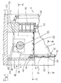
- the roller shutter device comprises a roller shutter shaft 20, a roller shutter armor 30, and a roller shutter housing 40 in which the roller shutter shaft 20 and in its rolled up State of the roller shutter curtain 30 are arranged.
- the inner wall of the roller shutter housing 40 arranged parallel to the window plane becomes through the top part of the window frame 10 and through a plate-shaped Frame widening element 42 formed, the part of a frame widening of Window frame 10 is.
- the one made of a well insulating plastic material Frame widening element 42 is the same thickness as the window frame 10. It is lying flush on the top of the window frame 10 and in alignment with this arranged in the wall light opening so that there is the gap between the top the window frame 10 and the underside of the lintel 2 completely filled and closes tightly.
- the outer wall of the roller shutter housing 40 is covered by a plate-shaped outer wall element 44 is formed, which is essentially the same Has length and width as the inner wall and is arranged parallel to this.
- the outer wall element 44 and the frame widening element 42 each via a plate-shaped side wall element 46 connected with each other.
- These two side wall elements 46 form the side walls of the roller shutter housing 40. They are perpendicular to the window plane and parallel to the Surfaces of the reveal 4 are arranged and their main surfaces lie directly on them Reveal areas 4.
- the interior wall, the side walls and the Outside wall of the roller shutter housing 40, a closed frame with a rectangular plan and four vertical walls formed in the Masonry opening just below the bottom of lintel 2 and between the two Reveal surfaces 4 of the wall light opening is arranged.
- the roller shutter shaft 20 is approximately in the middle between the inner wall and the Outside wall of the roller shutter housing 40 (i.e. in the outer space 8 in front of the frame widening element 42) arranged. It is parallel to the window plane and substantially horizontally arranged axis 22 rotatable, using suitable Storage and fastening means (not shown) on the side wall elements 46 and thus indirectly attached to the frame widening element 42. With others Variants of the invention can the roller shutter shaft by means of suitable bearings and holding means also be attached directly to the frame widening element.
- the roller shutter shaft 20 is via a gear 24 arranged in the roller shutter housing and a Intermediate shaft 26, which is formed by a in the frame widening element Bore is passed through, coupled to a manually operable crank 28.
- roller shutter shaft can 20 By rotating the crank 28 in one direction or the other, the roller shutter shaft can 20 are rotated in one direction or the other about their axis 22 roll up the roller shutter curtain 30 onto the roller shutter shaft 20 or roll it off. Furthermore, the roller shutter shaft 20 is in this way to the inner and outer wall of the roller shutter housing 40 and spaced from the underside of the lintel 2 that sufficient Space for a complete roll-up of the roller shutter curtain 30 on the Roller shutter shaft 20 is available.
- the clearances in the roller shutter housing 40 between that in its rolled-up state space taken up by the roller shutter curtain 30 and the housing walls of the Roller shutter housings 40 are made with a plurality of three-dimensional, made of styrofoam manufactured insulation body (not shown) filled, this insulation body optionally removable in the roller shutter housing 40 are mounted.
- these insulation bodies form a gearbox recess, which the gearbox 24 completely encloses. This remains due to the fact that the insulation body can be removed Gear 24 still accessible for service and repair purposes.
- the insulation bodies are designed such that they are inside the roller shutter housing 40 form a new reveal, which in comparison to the original reveal 4 the Masonry opening in the shell is shifted towards the middle of the masonry opening.
- the roller shutter curtain 30 is composed of a plurality of roller shutter slats 31, 32, 33 composed in the longitudinal direction (i.e. essentially parallel to the Roller shutter shaft 20) can be moved freely (i.e. indefinitely) with respect to one another.
- the Roller shutter curtain 30 is essentially along its entire winding and unwinding path and laterally in the rolled-up state on the roller shutter shaft 20. in the Roller shutter housing 40, this lateral guidance by the above described Reveals guaranteed from removable insulation bodies. Outside (i.e. below) of the roller shutter housing 40, the roller shutter armor is replaced by the following described guide rails 50 out.
- the roller shutter bars 31, 32, 33 are off Aluminum bar profiles made with a uniform cross-sectional profile.
- the Cross-sectional profile is designed such that it is on the upper edge of the roller shutter slats 31, 32, 33 a hook-shaped section and at the bottom an angular section forms, so that in each case the hook section of a roller shutter rod 32 in the corner section another roller shutter rod 31 arranged above this rod 32 can be suspended.
- a horizontally extending ledge 48 On the inside of the outer wall element 44 facing the roller shutter shaft 20 is a horizontally extending ledge 48 with an approximately angular one Cross section firmly attached.
- the cross section of Fig. 1 the vertical leg Corresponding plate section of this bar 48 is used to attach the bar 48 on Outer wall element 44, while that corresponding to the horizontal leg Panel part the actual holding down the Rolllatenpanzer 38 or with this connected suspension piece 38 is used.
- the bar 48 is opposite Roller shutter shaft 20 and arranged slightly below the same. It serves as Hold-down element 48 for holding down the roller shutter curtain 30 in its Roller shutter shaft 20 unrolled state and is part of a push-up protection for the Roller shutter curtain 30.
- the mounting position of the hold-down bar 48 on the outer wall element 44 is selected such that - when the roller shutter curtain 30 completely from the Roller shutter shaft 20 is unrolled - the upper edge of the roller shutter curtain 30 or top bar 31 slightly lower than the underside of hold-down bar 48 is arranged.
- At those points of the bar 48 which are in the longitudinal direction of the bar 48 are each opposite the leaf spring elements 36 described below in the horizontal plate section of the strip 48, recesses 49 in each case formed that the leaf spring elements 36 can be pushed into them.
- the uppermost roller shutter rod 31 of the roller shutter armor 30 is by means of suspension pieces 38 and elongated leaf spring elements 36 suspended from the roller shutter shaft 20.
- a leaf spring element 36 and a suspension piece 38 are shown in Figures 1 and 2.
- On Longitudinal end of the leaf spring element 36 is fixed to the peripheral surface of the roller shutter shaft 20 attached.
- a suspension piece 38 is attached, the is provided at its lower edge with a section which is angular in cross section, which is the same as the angular section at the lower edge of the roller shutter slats 31, 32, 33 is trained.
- the uppermost roller shutter rod 31 with its at the upper edge molded hook section on the angular section formed on the suspension piece 38 be attached.
- roller shutter shaft 20 If after reaching the position shown in broken lines in Fig. 1 the roller shutter shaft 20 is operated again in the winding direction, then the top one Roller shutter bar 31 and the suspension piece 38 first through the leaf spring element 36 pulled out from the hold-down bar 48 towards the roller shutter shaft 20, whereupon the roller shutter curtain 30 by a further actuation of the roller shutter shaft 20 in Rolling direction can be rolled up on this.
- the roller shutter device shown in FIGS. 1-3 including the Push-up protection for the roller shutter curtain is extremely space-saving become.
- the roller shutter device is dimensioned such that with the roller shutter curtain 30 completely unrolled from the roller shutter shaft, only the uppermost roller shutter rod 31 is partially arranged in the roller shutter housing.
- the Installation height of the entire roller shutter device is only just as high as it is due to the diameter of the roller shutter curtain in its rolled up condition is absolutely necessary.
- the required Shutter device according to the invention shown in Figures 1-3 only another installation height of about 18 cm.
- the roller shutter housing 40 Below the roller shutter housing 40 are 4 on the two reveal walls Wall light opening each a soffit 54 arranged, which the light width of the Reduce the opening of the wall light so that it is smaller than the length of the Roller shutter bars 31, 32, 33 defined width of the roller shutter curtain 30.
- the in the 3 shows a reveal bar 54 that extends in FIG vertical direction over the entire height between the parapet Wall light opening and the shutter housing 40. Your the middle of the wall light opening facing side surface defines the actual reveal in this height range or reveal surface of the wall light opening.
- a groove 58 is formed, which is in the Extends substantially over the entire height of the reveal bar 54.
- this groove 58 a guide rail 50 made of an aluminum profile is arranged, which the lateral guidance of the roller shutter curtain 30 in the area below the roller shutter housing 40 serves.
- the arrangement of the guide rail 50 in the groove 58 is the Guide rail 50 covered and thereby against a prying open for the purpose Burglary protected.
- the guide rail 50 is further parallel to the reveal surface arranged and provided on this plate section 52, which are parallel extends to the reveal surface beyond the outer edge of the reveal strip 54.
- This A plate section 52 protruding beyond the outer edge of the reveal strip 54 forms one End screen 52 for an exterior plaster 56, which in the reveal on the Outside of the wall is applied, in which the wall light opening is formed is.
- the roller shutter device shown in Figs. 1-3 is further provided with a bottom cover 60 provided, which the underside of the roller shutter housing 40 optionally releasable concludes.
- the bottom view panel 60 of the roller shutter housing 40 is made up of a plurality composed of roller shutter rods, which to the roller shutter rods 31, 32, 33 of Roller shutter curtain 30 are identical.
- the bottom view panel 60 is thus in the manner of a the roller shutter armor section corresponding to 30 and made transverse to the longitudinal direction of the roller shutter slats just as flexible as the roller shutter curtain 30th
- the frame widening element is first used in a manufacturing facility 42 that outer wall element 44 with attached Hold-down bar 48 and the two side wall elements 46 of the roller shutter housing 40 assembled into a roller shutter housing frame and firmly together connected.
- the roller shutter shaft 20 is still in the factory together with their gear 24 attached to this shutter housing frame.
- the from the roller shutter housing frame with built-in Roller shutter shaft 20 formed assembly unit transported to the building Wall light opening the roller shutter device is to be installed.
- the assembly unit is there afterwards installed as a whole in the wall light opening. After that you can Windows, the roller shutter curtain 30 and the other components of the wall light opening final window arrangement.
- the invention provides a roller shutter device is specified, which is comparatively easy to assemble and good Has insulation properties.
Landscapes
- Engineering & Computer Science (AREA)
- Structural Engineering (AREA)
- Architecture (AREA)
- Civil Engineering (AREA)
- Operating, Guiding And Securing Of Roll- Type Closing Members (AREA)
Abstract
Description
- Fig. 1
- eine Rollladenvorrichtung gemäss einer bevorzugten Ausführungsart der Erfindung in einer vereinfachten, teilweise geschnittenen Teilansicht von der Seite;
- Fig. 2
- die Rollladenvorrichtung aus Fig. 1 in einer vereinfachten Querschnittansicht entlang der Linie A-A;
- Fig. 3
- in einer vereinfachten Querschnittansicht entlang der Linie B-B ein Detail der Rollladenvorrichtung aus Fig. 1.
Claims (14)
- Rollladenvorrichtung mit einer Rollladenwelle (20), für einen Mauerlichtöffnungsabschluss, der einen Aussenraum (8) von einem Innenraum (6) trennt und mit einem starr in einer Mauerlichtöffnung anzuordnenden Rahmen (10) versehen ist, dadurch gekennzeichnet, dass die Rollladenvorrichtung weiter ein Rahmenverbreiterungselement (42) mit einer flachen Plattenpartie aufweist, die Teil einer Rahmenverbreiterung des Rahmens (10) ist, wobei die Rollladenwelle (20) derart im Aussenraum (8) vor der Plattenpartie angeordnet und am Rahmenverbreiterungselement (42) angebracht ist, dass auf die Rollladenwelle (20) ein Rollladenpanzer (30) aufrollbar ist.
- Rollladenvorrichtung nach Anspruch 1, dadurch gekennzeichnet, dass die Plattenpartie des Rahmenverbreiterungselements (42) mit ihrer Aussenseite zur Aussenseite des Rahmens (10) fluchtend angeordnet und vorzugsweise im Wesentlichen gleich dick wie der Rahmen (10) ist.
- Rollladenvorrichtung nach Anspruch 1 oder 2, dadurch gekennzeichnet, dass sie weiter ein flaches Aussenwandelement (44) aufweist, das auf der der Plattenpartie gegenüberliegenden Seite der Rollladenwelle (20) im Wesentlichen parallel zur Plattenpartie des Rahmenverbreiterungselements (42) derart angeordnet und mit diesem verbunden ist, dass die Plattenpartie wenigstens einen Teil der Innenwand und das Aussenwandelement (44) wenigstens einen Teil der Aussenwand eines die Rollladenwelle (20) umgebenden Rollladengehäuses (40) definieren.
- Rollladenvorrichtung insbesondere nach einem der Ansprüche 1 bis 3, mit einem wenigstens eine Innenwand und eine Aussenwand aufweisenden Rollladengehäuse (40) und einer Rollladenwelle (20), die am Rollladengehäuse (40) angebracht und derart zwischen der Innen- und der Aussenwand angeordnet ist, dass auf sie ein Rollladenpanzer (30) aufrollbar ist, dadurch gekennzeichnet, dass die Rollladenvorrichtung weiter eine Mehrzahl von Isolationskörpern umfasst, die zum wahlweise wieder demontierbaren Montieren im Rollladengehäuse (40) zwischen den beiden Rollladengehäusewänden derart ausgebildet sind, dass sie in im Rollladengehäuse (40) montierten Zustand das Aufrollen des Rollladenpanzers (30) auf die Rollladenwelle (20) und das Abrollen des Rollladenpanzers (30) von der Rollladenwelle (20) nicht behindern.
- Rollladenvorrichtung nach Anspruch 4, gekennzeichnet durch die Ausbildung der Isolationskörper derart, dass sie in einer Anordnung im Rollladengehäuse (40) montierbar sind, in welcher sie mit Ausnahme eines der Rollladenpanzerbreite entsprechenden Freiraumbereichs im Wesentlichen den gesamten Freiraum im Rollladengehäuse (40) ausfüllen.
- Rollladenvorrichtung nach Anspruch 4 oder 5, gekennzeichnet durch die Ausbildung der Isolationskörper derart, dass wenigstens ein Isolationskörper im Rollladengehäuse (40) in einer eine Partie der Leibung der Mauerlichtöffnung bildenden und den Rollladenpanzer (30) seitlich führenden Anordnung montierbar ist.
- Rollladenvorrichtung nach Anspruch 6, dadurch gekennzeichnet, dass sie weiter einen auf die Rollladenwelle (20) aufrollbaren und von dieser wieder abrollbaren Rollladenpanzer (30) umfasst, der aus einer Vielzahl von Rollladenstäben (31, 32, 33) zusammengesetzt ist, die in Stablängsrichtung bezüglich einander frei verschiebbar sind.
- Rollladenvorrichtung insbesondere nach einem der Ansprüche 1 bis 7, mit einem wenigstens eine Innenwand und eine Aussenwand aufweisenden Rollladengehäuse (40), einem Rollladenpanzer (30) und einer Rollladenwelle (20), die am Rollladengehäuse (40) angebracht und derart zwischen der Innen- und der Aussenwand angeordnet ist, dass der Rollladenpanzer (30) wahlweise auf sie aufrollbar und von ihr abrollbar ist, dadurch gekennzeichnet, dass die Rollladenvorrichtung weiter wenigstens ein Niederhalteelement (48) aufweist, das fest am Rollladengehäuse (40) angebracht und derart angeordnet ist, dass in von der Rollladenwelle (20) abgerolltem Zustand des Rollladenpanzers (30) ein Anschlag des Rollladenpanzers (30) derart unter das Niederhalteelement (48) bringbar ist, dass der Rollladenpanzer (30) gegen ein Hochschieben nach oben gesichert ist.
- Rollladenvorrichtung nach Anspruch 8, dadurch gekennzeichnet, dass der Rollladenpanzer (30) im Bereich seines oberen Endes mittels von federnden Aufhängeelementen (36) derart an der Rollladenwelle (20) aufgehängt ist, dass, wenn nach dem Abrollen des Rollladenpanzers (30) von der Rollladenwelle (20) die Rollladenwelle (20) weiter in Abrollrichtung betätigt wird, der obere Endbereich des Rollladenpanzers (30) derart von der Rollladenwelle (20) weg bewegt wird, dass der Anschlag selbsttätig unter das Niederhalteelement (48) gebracht wird, und wenn danach die Rollladenwelle (20) in Aufrollrichtung betätigt wird, der obere Endbereich des Rollladenpanzers (30) derart zur Rollladenwelle (20) hin bewegt wird, dass der Anschlag selbsttätig wieder unter dem Niederhalteelement (48) hervorgeholt wird.
- Rollladenvorrichtung für einen Mauerlichtöffnungsabschluss insbesondere nach einem der Ansprüche 1 bis 9, mit einer Rollladenwelle (20), einem wahlweise auf die Rollladenwelle (20) aufrollbaren und von dieser abrollbaren Rollladenpanzer (30) und wenigstens einer Führungsschiene (50) zur seitlichen Führung des Rollladenpanzers (30) während dem Auf- und Abrollen, dadurch gekennzeichnet, dass die Führungsschiene (50) in einer Nut (58) angeordnet ist, die in einerLeibung der Mauerlichtöffnung ausgebildet ist.
- Rollladenvorrichtung nach Anspruch 10, dadurch gekennzeichnet, dass die Führungsschiene (50) mit einer parallel zur Leibungsoberfläche angeordneten und auf dieser aufliegenden Plattenpartie (52) versehen ist, die derart bemessen und ausgebildet ist, dass sie auf der Aussenseite der Mauerlichtöffnung über den Rand der Leibung hinaus vorsteht und eine Abschlussblende für einen Aussenputz (56) bildet, der im Bereich der Leibung auf die Aussenseite der Mauer aufzutragen ist, in welcher die Mauerlichtöffnung ausgebildet ist.
- Rollladenvorrichtung insbesondere nach einem der Ansprüche 1 bis 11, mit einem wenigstens eine Innenwand und eine Aussenwand aufweisenden Rollladengehäuse (40), einer am Rollladengehäuse (40) angebrachten und zwischen deren Innen- und Aussenwand angeordneten Rollladenwelle (20), auf die ein Rollladenpanzer (30) aufrollbar ist , und einer an der Unterseite des Rollladengehäuses (40) anzuordnenden Untersichtblende (60), dadurch gekennzeichnet, dass die Untersichtblende (60) als flexible, biegsame Einheit ausgebildet ist.
- Rollladenvorrichtung nach Anspruch 12, dadurch gekennzeichnet, dass sie weiter einen auf die Rollladenwelle (20) aufrollbaren Rollladenpanzer (30) umfasst, der aus einer Vielzahl von Rollladenstäben (31, 32, 33) zusammengesetzt ist, und dass die Untersichtblende (60) aus einer Mehrzahl von Rollladenstäben zusammengesetzt ist, die zu den Rollladenstäben (31, 32, 33) des Rollladenpanzers (30) identisch sind.
- Verfahren zum Einbauen einer Rollladenvorrichtung mit einer Rollladenwelle (20) und einem Rahmenverbreiterungselement (42) mit einer flachen Plattenpartie nach einem der Ansprüche 1 bis 13 in eine Mauerlichtöffnung eines Gebäudes, dadurch gekennzeichnet, dass in einem ersten Schritt in einer vom Gebäude distanzierten Fabrikationsstätte die Rollladenwelle (20) am Rahmenverbreiterungselement (42) fest angebracht und somit eine die Rollladenwelle (20) und das Rahmenverbreiterungselement (42) umfassende Montageeinheit hergestellt wird, in einem zweiten Schritt die Montageeinheit zum Gebäude transportiert und in einem dritten Schritt die Montageeinheit als Ganzes in die Mauerlichtöffnung eingebaut wird.
Priority Applications (2)
| Application Number | Priority Date | Filing Date | Title |
|---|---|---|---|
| EP01810978A EP1300540A1 (de) | 2001-10-08 | 2001-10-08 | Rolladenvorrichtung |
| EP02022578A EP1300542A1 (de) | 2001-10-08 | 2002-10-08 | Rollblendenvorrichtung |
Applications Claiming Priority (1)
| Application Number | Priority Date | Filing Date | Title |
|---|---|---|---|
| EP01810978A EP1300540A1 (de) | 2001-10-08 | 2001-10-08 | Rolladenvorrichtung |
Publications (1)
| Publication Number | Publication Date |
|---|---|
| EP1300540A1 true EP1300540A1 (de) | 2003-04-09 |
Family
ID=8184180
Family Applications (1)
| Application Number | Title | Priority Date | Filing Date |
|---|---|---|---|
| EP01810978A Withdrawn EP1300540A1 (de) | 2001-10-08 | 2001-10-08 | Rolladenvorrichtung |
Country Status (1)
| Country | Link |
|---|---|
| EP (1) | EP1300540A1 (de) |
Citations (8)
| Publication number | Priority date | Publication date | Assignee | Title |
|---|---|---|---|---|
| DE7822165U1 (de) * | 1978-07-24 | 1978-10-26 | Stahl-Schanz Gmbh & Co Kg 6052 Muehlheim | Als rolladenkasten ausgebildeter fenstersturz |
| EP0155659A2 (de) * | 1984-03-21 | 1985-09-25 | Abito Finanz- und Handelsgesellschaft AG | Rolladen zum wahlweisen Verschliessen von Oeffnungen |
| CH666323A5 (en) * | 1984-11-22 | 1988-07-15 | Zuercher Ziegeleien | Door or window frame lintel for mounting roller blind etc. - has housing with front, rear and top wall of glass fibre reinforced concrete, trough-shaped rear wall has recess for roller |
| EP0530168A1 (de) * | 1991-08-23 | 1993-03-03 | Dotesa Engineering Bv | Sperrvorrichtung für Rolltoren |
| CH687403A5 (de) * | 1992-11-12 | 1996-11-29 | Franz Kraler | Verlorene Schalung mit einem ersten Schalungsabschnitt. |
| DE19746019A1 (de) * | 1996-11-14 | 1998-05-20 | Reinhard Spannbauer | Rolladensturz |
| FR2765911A1 (fr) * | 1997-07-11 | 1999-01-15 | Daniel Bracq | Dispositif de blocage pour volet roulant |
| DE20104454U1 (de) * | 2001-03-12 | 2001-06-21 | Friedrich, Hans, 56566 Neuwied | Rolladenkasten |
-
2001
- 2001-10-08 EP EP01810978A patent/EP1300540A1/de not_active Withdrawn
Patent Citations (8)
| Publication number | Priority date | Publication date | Assignee | Title |
|---|---|---|---|---|
| DE7822165U1 (de) * | 1978-07-24 | 1978-10-26 | Stahl-Schanz Gmbh & Co Kg 6052 Muehlheim | Als rolladenkasten ausgebildeter fenstersturz |
| EP0155659A2 (de) * | 1984-03-21 | 1985-09-25 | Abito Finanz- und Handelsgesellschaft AG | Rolladen zum wahlweisen Verschliessen von Oeffnungen |
| CH666323A5 (en) * | 1984-11-22 | 1988-07-15 | Zuercher Ziegeleien | Door or window frame lintel for mounting roller blind etc. - has housing with front, rear and top wall of glass fibre reinforced concrete, trough-shaped rear wall has recess for roller |
| EP0530168A1 (de) * | 1991-08-23 | 1993-03-03 | Dotesa Engineering Bv | Sperrvorrichtung für Rolltoren |
| CH687403A5 (de) * | 1992-11-12 | 1996-11-29 | Franz Kraler | Verlorene Schalung mit einem ersten Schalungsabschnitt. |
| DE19746019A1 (de) * | 1996-11-14 | 1998-05-20 | Reinhard Spannbauer | Rolladensturz |
| FR2765911A1 (fr) * | 1997-07-11 | 1999-01-15 | Daniel Bracq | Dispositif de blocage pour volet roulant |
| DE20104454U1 (de) * | 2001-03-12 | 2001-06-21 | Friedrich, Hans, 56566 Neuwied | Rolladenkasten |
Similar Documents
| Publication | Publication Date | Title |
|---|---|---|
| DE2339596A1 (de) | Rollvorhang-anordnung | |
| EP0169918A1 (de) | Wärmedämmendes Fenster | |
| EP2923024B1 (de) | Abdeckvorrichtung | |
| EP3540172B1 (de) | Vorsatzschalenanordnung für ein verbundfenster sowie damit ausgebildetes verbundfenster | |
| EP0747565A1 (de) | Einbauelement für den Abschluss einer Gebäudeöffnung | |
| EP1091081A2 (de) | Führungsvorrichtung für einen Rollladen, ein Rollo oder dgl | |
| EP0738821B1 (de) | Aufnahmekasten zur Aufnahme eines Rolladenpanzers sowie eines Spring-, Lamellen- oder Raffrollos | |
| DE202009013560U1 (de) | Gebäudeöffnungsverschattungsvorrichtung und Führungsschienenmodul dafür | |
| DE19963919B4 (de) | Verfahren und Einrichtung zum wärmeverlustarmen Belüften von Räumen über eine oder mehrere Fenster/Tür-Rollladenanordnungen | |
| EP1300542A1 (de) | Rollblendenvorrichtung | |
| EP0132779A2 (de) | Fensterzarge | |
| EP1106772A1 (de) | Rolladen-Aufsatzkasten | |
| EP1878866B1 (de) | Leibungselement | |
| AT508177B1 (de) | Rollladen mit führungsschienen und anschlägen | |
| EP1300540A1 (de) | Rolladenvorrichtung | |
| EP3441557B1 (de) | Torvorrichtung mit einer türvorrichtung | |
| DE8327232U1 (de) | Jalousie zum abdecken einer wandoeffnung | |
| EP1172513B1 (de) | Aufnahmekasten für Sonnenschutz-, Wetterschutz- und/oder Verdunklungseinrichtungen an Fenstern und Türen | |
| EP4446556B1 (de) | Gebäudeöffnungsverschattungsvorrichtung und seitenführungsschiene hierfür | |
| DE102014001887A1 (de) | Gebäudeöffnungsverschattungsvorrichtung und Führungsschiene dafür | |
| DE202005002160U1 (de) | Rolladen-Vorrichtung | |
| DE4336069C2 (de) | Rolladenkonstruktion | |
| DE19839332A1 (de) | Multifunktionsrolladen | |
| DE3227721A1 (de) | Rolladen fuer fenster und tueren an gebaeuden | |
| DE8633840U1 (de) | Vorgefertigte Fenster- und Rolladenvorrichtung für Häuser u. dgl. |
Legal Events
| Date | Code | Title | Description |
|---|---|---|---|
| PUAI | Public reference made under article 153(3) epc to a published international application that has entered the european phase |
Free format text: ORIGINAL CODE: 0009012 |
|
| AK | Designated contracting states |
Kind code of ref document: A1 Designated state(s): AT BE CH CY DE DK ES FI FR GB GR IE IT LI LU MC NL PT SE TR Designated state(s): AT BE CH CY DE DK ES FI FR GB GR IE IT LI LU MC NL PT SE TR |
|
| AX | Request for extension of the european patent |
Extension state: AL LT LV MK RO SI |
|
| AKX | Designation fees paid | ||
| REG | Reference to a national code |
Ref country code: DE Ref legal event code: 8566 |
|
| STAA | Information on the status of an ep patent application or granted ep patent |
Free format text: STATUS: THE APPLICATION IS DEEMED TO BE WITHDRAWN |
|
| 18D | Application deemed to be withdrawn |
Effective date: 20031010 |