EP1300573A2 - Méthode pour contrôler un moteur à combustion interne à injection directe, appareil de commande et moteur à combustion - Google Patents
Méthode pour contrôler un moteur à combustion interne à injection directe, appareil de commande et moteur à combustion Download PDFInfo
- Publication number
- EP1300573A2 EP1300573A2 EP02017580A EP02017580A EP1300573A2 EP 1300573 A2 EP1300573 A2 EP 1300573A2 EP 02017580 A EP02017580 A EP 02017580A EP 02017580 A EP02017580 A EP 02017580A EP 1300573 A2 EP1300573 A2 EP 1300573A2
- Authority
- EP
- European Patent Office
- Prior art keywords
- lambda
- lean
- operating mode
- combustion engine
- internal combustion
- Prior art date
- Legal status (The legal status is an assumption and is not a legal conclusion. Google has not performed a legal analysis and makes no representation as to the accuracy of the status listed.)
- Granted
Links
Images


Classifications
-
- F—MECHANICAL ENGINEERING; LIGHTING; HEATING; WEAPONS; BLASTING
- F02—COMBUSTION ENGINES; HOT-GAS OR COMBUSTION-PRODUCT ENGINE PLANTS
- F02D—CONTROLLING COMBUSTION ENGINES
- F02D41/00—Electrical control of supply of combustible mixture or its constituents
- F02D41/30—Controlling fuel injection
- F02D41/3011—Controlling fuel injection according to or using specific or several modes of combustion
- F02D41/3017—Controlling fuel injection according to or using specific or several modes of combustion characterised by the mode(s) being used
- F02D41/3023—Controlling fuel injection according to or using specific or several modes of combustion characterised by the mode(s) being used a mode being the stratified charge spark-ignited mode
- F02D41/3029—Controlling fuel injection according to or using specific or several modes of combustion characterised by the mode(s) being used a mode being the stratified charge spark-ignited mode further comprising a homogeneous charge spark-ignited mode
-
- F—MECHANICAL ENGINEERING; LIGHTING; HEATING; WEAPONS; BLASTING
- F02—COMBUSTION ENGINES; HOT-GAS OR COMBUSTION-PRODUCT ENGINE PLANTS
- F02D—CONTROLLING COMBUSTION ENGINES
- F02D41/00—Electrical control of supply of combustible mixture or its constituents
- F02D41/30—Controlling fuel injection
- F02D41/3011—Controlling fuel injection according to or using specific or several modes of combustion
- F02D41/3064—Controlling fuel injection according to or using specific or several modes of combustion with special control during transition between modes
- F02D41/307—Controlling fuel injection according to or using specific or several modes of combustion with special control during transition between modes to avoid torque shocks
-
- F—MECHANICAL ENGINEERING; LIGHTING; HEATING; WEAPONS; BLASTING
- F02—COMBUSTION ENGINES; HOT-GAS OR COMBUSTION-PRODUCT ENGINE PLANTS
- F02D—CONTROLLING COMBUSTION ENGINES
- F02D41/00—Electrical control of supply of combustible mixture or its constituents
- F02D41/30—Controlling fuel injection
- F02D41/38—Controlling fuel injection of the high pressure type
- F02D2041/389—Controlling fuel injection of the high pressure type for injecting directly into the cylinder
-
- F—MECHANICAL ENGINEERING; LIGHTING; HEATING; WEAPONS; BLASTING
- F02—COMBUSTION ENGINES; HOT-GAS OR COMBUSTION-PRODUCT ENGINE PLANTS
- F02D—CONTROLLING COMBUSTION ENGINES
- F02D2250/00—Engine control related to specific problems or objectives
- F02D2250/18—Control of the engine output torque
-
- F—MECHANICAL ENGINEERING; LIGHTING; HEATING; WEAPONS; BLASTING
- F02—COMBUSTION ENGINES; HOT-GAS OR COMBUSTION-PRODUCT ENGINE PLANTS
- F02D—CONTROLLING COMBUSTION ENGINES
- F02D41/00—Electrical control of supply of combustible mixture or its constituents
- F02D41/02—Circuit arrangements for generating control signals
- F02D41/14—Introducing closed-loop corrections
- F02D41/1438—Introducing closed-loop corrections using means for determining characteristics of the combustion gases; Sensors therefor
- F02D41/1444—Introducing closed-loop corrections using means for determining characteristics of the combustion gases; Sensors therefor characterised by the characteristics of the combustion gases
- F02D41/1454—Introducing closed-loop corrections using means for determining characteristics of the combustion gases; Sensors therefor characterised by the characteristics of the combustion gases the characteristics being an oxygen content or concentration or the air-fuel ratio
Definitions
- the invention relates to a method for operating a direct injection internal combustion engine.
- the invention further relates to a computer program for a Internal combustion engine, a control device for operating a direct injection internal combustion engine and a direct injection internal combustion engine.
- a method of operating a direct injection Internal combustion engine is compared to the prior art further developed in that the internal combustion engine at least in a lean operating mode with homogeneous Character (HMM) is operated, being in the operating mode constant lambda value is sought, with the Lambda values between a lower and an upper lambda limit move and being in certain Operating situations an expansion of the lambda limit values is made.
- HMM homogeneous Character
- the preferred training of The method according to the invention provides that the specific Operating situations at least switching from one any operating mode into the lean operating mode with homogeneous character, from the lean operating mode with homogeneous character in any other operating mode or a quick torque request in the stationary Operation include.
- the great advantage of the invention is that the torque of the Internal combustion engine almost at the desired torque can be held.
- the expansion of the lambda limit values is withdrawn as soon as the specific operating situation is no longer available. This makes sense because in the Period of expansion of the lambda limits increased NOx emissions respectively. Due to the short-term expansion of the Lambda limits will be an optimal compromise between low NOx emissions and driveability (with the desired Target torque) closed.
- the Lambda limits such that an approximately constant Torque is generated by the internal combustion engine.
- HMM homogeneous character
- a further development of the method according to the invention provides before that the upper and lower lambda limit to the same target lambda limit, with the Target lambda limit the desired constant lambda value equivalent.
- the expansion of the lambda limit values is particularly advantageous be withdrawn without it illegal lambda actual values and thus too Torque fluctuations come.
- a further development of the method according to the invention provides before that a lambda curve is observed that it is determined whether the lambda curve in the direction of rich or runs towards lean that if the lambda curve runs in the direction of bold, the upper, lean lambda limit is not expanded and that if the The lambda curve runs towards lean, the lower, fat one Lambda limit is not expanded.
- This measure has the advantage that the distance between the top and the lower lambda limit is reduced, which is a sudden lambda change, for example due to highly dynamic torque requirements, to a lower one Value limited than it is without the invention Continuing education would be the case.
- An alternative training option of the The method according to the invention provides that a lambda curve it is observed that it is determined whether the Lambda curve towards rich or towards lean that runs when the lambda curve goes in the direction runs bold, the upper, lean lambda limit dem Lambda curve is tracked and that when the The lambda curve runs towards lean, the lower, fat one Lambda limit is tracked the lambda curve.
- the method according to the invention becomes a sudden change in the actual lambda value almost completely suppressed. So there is an actual lambda deviation not tolerated by the target lambda value.
- the advantage is that with a highly dynamic Torque request no unsteady actual lambda values Consequence are, but that the actual actual lambda not very far from the target lambda value.
- a computer program according to the invention for a Internal combustion engine with a sequence of commands according to the invention suitable for that described above Procedure to perform when the sequence of commands is up a computer, in particular a control unit for a Internal combustion engine to be run.
- the computer program can be developed according to the invention in that the Sequence of commands on a computer readable medium is saved. So in this case it will methods according to the invention in the form of a computer program, that for an internal combustion engine, especially one Motor vehicle, is provided.
- computer-readable data media for example a floppy disk, a compact disk or a so-called Trade flash memory.
- the computer program can, if necessary, together with other computer programs as a software product for example to a manufacturer of control units for Internal combustion engines are sold.
- the transmission of the Software product can be sent by sending a Diskette or a CD, the content of which Control unit manufacturer then transfers to the control unit. It is also possible that a flash memory is attached to the Control unit manufacturer is sent, which this directly in the control unit uses. It is also possible that Software product via an electronic communication network, especially on the Internet, to the ECU manufacturer is transmitted. In this case provides the software product as such - regardless of an electronic storage medium - the sales product In this case, the control unit manufacturer loads the Software product e.g. B. down from the Internet to it then save it, for example, on a flash memory and insert it into the control unit.
- the computer program can also be used as a separate software product are distributed by a manufacturer of control units together with other third party software products Manufacturer transfers into the control unit. In this case sets the software product according to the invention to others Modules from third-party manufacturers are compatible.
- a control device for operating a direct injection internal combustion engine is thereby further developed that the internal combustion engine from that Control unit at least in a lean operating mode homogeneous character (HMM) is controlled, in which Operating mode a constant lambda value is aimed for, where the lambda values are between a lower and a move upper lambda limit and being in certain Operating situations an expansion of the lambda limit values is made.
- HMM lean operating mode homogeneous character
- a direct injection internal combustion engine according to the invention is further developed compared to the prior art that the internal combustion engine is at least in a lean Operating mode with homogeneous character (HMM) is operated, with a constant lambda value in this operating mode is aimed for, the lambda values between one move lower and an upper lambda limit and where in certain operating situations an expansion of the Lambda limits are made.
- HMM homogeneous character
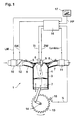
- FIG. 1 shows an embodiment of a Direct-injection internal combustion engine according to the invention.
- a piston 2 is in one Cylinder 3 can be moved back and forth.
- the cylinder 3 is with a combustion chamber 4, to which via valves 5 Intake pipe 6 and an exhaust pipe 7 are connected.
- the combustion chamber 4 also includes a signal TI controllable injection valve 8 and one with a signal ZW controllable spark plug 9 connected.
- the signals TI and ZW are here from a control unit 16 to the Transfer the injection valve 8 or the spark plug 9.
- the intake pipe 6 is with an air mass sensor 10 and that Exhaust pipe 7 provided with a lambda sensor 11.
- the Air mass sensor 10 measures the air mass of the intake pipe 6 fresh air supplied and generated depending on it Signal LM.
- the lambda sensor 11 measures the oxygen content of the exhaust gas in the exhaust pipe 7 and generated depending of which a signal Lambda.
- the air mass sensor signals 10 and the lambda sensor 11 are the control unit 16th fed.
- a throttle valve 12 is accommodated in the intake pipe 6, whose rotary position is adjustable by means of a signal DK.
- the exhaust pipe 7 can not be here Exhaust gas recirculation line (EGR) shown with the Intake pipe 6 may be connected.
- EGR Exhaust gas recirculation line
- the control of the Exhaust gas recirculation can, for example, via one of the Control device 16 controllable, also not here Exhaust gas recirculation valve shown.
- the homogeneous operation of the Internal combustion engine 1 the throttle valve 12 in Dependence on the desired air mass supplied partially opened or closed.
- the fuel is from the injection valve 8 during a through the piston 2 induced suction phase injected into the combustion chamber 4.
- the air sucked in at the same time injected fuel swirls and thus in the combustion chamber 4 essentially evenly / homogeneously distributed.
- the fuel-air mixture during the compression phase compressed to be ignited by the spark plug 9. Due to the expansion of the ignited fuel Piston 2 driven.
- the throttle valve 12 becomes wide opened (Lambda >> 1).
- the fuel is from that Injector 8 during a through the piston 2nd compression phase in the combustion chamber 4 injected.
- the spark plug 9 Fuel ignited, so that the piston 2 in the now following working phase by the expansion of the inflamed Fuel is driven.
- HMM homogeneous Lean operation
- the fuel as with Homogeneous operation, during the intake phase in the combustion chamber 4 is injected.
- an air / fuel mixture of lambda> 1 is set.
- a lambda value of approximately 1.6 is ideal for a stationary homogeneous lean operation HMM with a Exhaust gas recirculation rate (EGR) of 0% considered.
- EGR Exhaust gas recirculation rate
- the homogeneous lean operating mode HMM is a basically lean operating mode with homogeneous character, the operating mode as a air-controlled operating mode (like homogeneous operation) must be considered.
- Air-guided means here that the quantity influencing the torque the amount of air supplied is.
- the internal combustion engine 1 can be controlled using the control unit 16 switch between the different operating modes.
- All operating modes are driven by the driven piston 2 a crankshaft 14 is rotated through which ultimately driven the wheels of the motor vehicle become.
- a gearwheel is arranged on the crankshaft 14, whose teeth are arranged directly opposite one another Speed sensor 15 are scanned.
- the speed sensor 15 generates a signal from which the speed n of the crankshaft 14 is determined and transmits this signal n to the Control unit 16.
- that of the Injector 8 injected into the combustion chamber Fuel mass from the control unit 16, in particular in the With regard to low fuel consumption and / or a low level of pollutants and / or a desired one Target torque controlled and / or regulated.
- control unit 16 provided with a microprocessor, which in one Storage medium program code has been saved, the addition is suitable, the entire control system according to the invention and / or control of the internal combustion engine 1.
- the control device 16 is also equipped with a Accelerator pedal sensor 17 connected, which generates a signal FP, the the position of a driver-operated Accelerator pedals / accelerator pedals and thus that of the driver indicates requested moment. According to others Operating conditions and the moment requested by the driver is the control unit 16 which is currently to be executed Operating mode selected and controlled accordingly and / or regulated.
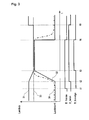
- FIG. 2 shows a first embodiment of the inventive method for operating a direct injection internal combustion engine.
- 4 and 5 is in Figure 2 on the horizontal axis plotted the time.
- the vertical Axis represents lambda values.
- the Signal curve B_hmms represents the signal that the Operating mode homogeneous / lean (HMM) was requested. This thus practically represents the target state of the operating mode.
- the second signal curve B_hmm represents the actual state of the Operating mode homogeneous / lean (HMM). Whenever B_hmm high level, the operating mode becomes homogeneous / lean (HMM) executed.
- the third waveform B_hmmlgs means that whenever this signal is high level has the operating mode homogeneous / lean HMM air-controlled and with constant lambda limits is executed.
- the curve shape 21 represents one Upper lambda limit for the homogeneous / lean HMM operating mode represents and the curve shape 22 a lower lambda limit for the operating mode homogeneous / lean HMM.
- the course 23 indicates a target lambda or a target lambda, the actual actual lambda value during the curve 24 describes.
- the figure in FIG illustrated history a transition from any other operating mode to the homogeneous / lean operating mode (HMM) and back.
- HMM homogeneous / lean operating mode
- a homogeneous operating mode was predominant.
- the driver of the motor vehicle Reduced torque request or goes off the gas runs Lambda value in the lean direction, which means that at time t1 Signal B_hmms is set high, which means the operating mode Homogeneous / lean is requested.
- the driver of the motor vehicle Torque request in turn increased by pressing the accelerator pedal suppressed.
- Time t1 becomes the transition from the time t2 Homogeneous operating mode to the homogeneous / lean operating mode started by the high level of the signal B_hmm is recognizable.
- the lambda limits 21 and 22 Ramped to the target lambda value 23, causing the lambda value is forced to move within the given corridor move.
- the actual lambda curve that arises 24 shows that the lambda value up to time t3 does not touch the lower lambda limit 22, so in this Range the lambda limits 21 and 22 as a pure one Safety function can be seen.
- time t3 the Actual lambda value 24 approximates target lambda value 23 reached and the upper and lower lambda limits 21 and 22 respectively are at approximately the same constant value set.
- the operating mode Homogeneous / lean as air-guided operating mode with constant Lambda value executed which is indicated by the signal B_hmmlgs and whose high level is specified from time t3.
- the Time span between times t3 and the following In practice, time t31 can be as long as desired as long as no specific operating situation occurs in which must be deviated from the air-guided mode of operation.
- the representation according to FIG. 2 shows on the one hand Transition from a homogeneous mode of operation to the Homogeneous / lean operating mode and back to the homogeneous Operation.
- the driving scenario would be approximately that The following: At a time t1, the driver of the Motor vehicle to accelerate its vehicle, causing a shift mode that is particularly lean to Time t2 changed to a homogeneous / lean operating mode becomes, and finally from time t5 to a homogeneous Operating mode is changed because the required torque no longer available in the homogeneously lean operating mode can be put.
- the curve shape 31 represents the upper and the Curve 32 the lower lambda limit for the Operating mode homogeneous / lean HMM.
- Curve 33 shows shows the desired lambda target value and curve shape 34 the actual lambda value.
- Figure 2 in the Representation according to FIG. 3 not a highly dynamic one Torque intervention between times t3 and z4 shown. The other curves, however, are correct until Time t4 with the corresponding curve profiles after Figure 2 match.
- This configuration of the The method according to the invention offers the advantage that a possibly between times t4 and t5 occurring highly dynamic instantaneous requirement regarding the rapid lambda change to a maximum lambda jump from the current actual lambda curve 34 to the upper one Lambda limit 31 is limited. Because the lambda jump is limited and of course a moment jump or a jolt of the motor vehicle must be avoided further measures the limited lambda jump compensate.
- the homogeneous-lean operating mode is ended at time t5, B_hmm goes to low level and it starts Homogeneous operating mode. Simultaneously with the beginning of the The homogeneous operating mode from time t5 also becomes the upper one Lambda limit released. The corresponding ones apply here Notes from Figure 2.
- FIG. 4 essentially shows the embodiment according to FIG 3, only that in FIG. 4 a time before time t2 Shift mode is active and the actual lambda curve 44 at time t4 runs towards lean.
- the presence the shift mode before time t2 can be on Recognize the course of the actual lambda curve 44, which is characterized by high lean lambda values. Since the actual lambda curve 44 from the time t4 onwards becomes lean 4 shows the lower, fat lambda limit for the Operating mode homogeneous / lean HMM 42 left unchanged and only the upper lambda limit for the operating mode Homogeneous / lean HMM 41 expanded.
- Figure 5 shows another embodiment of the inventive method.
- the curves correspond essentially those according to FIG. 3.
- the curves 51 and 52 are the upper and lower lambda limits for the Operating mode homogeneous / lean HMM.
- Curve 53 is the lambda setpoint and curve 54 represents the actual lambda value Differences from FIG. 3 come into effect from time t4 wear. Also in the embodiment of Figure 5 From time t4 the further actual lambda curve 54 observed. It is found that the actual lambda curve 54 runs in the direction of richer lambda values.
- the lean lambda limit 51 becomes the actual lambda value from time t4 54 tracked what the possibility of a lambda jump towards lean at a possible highly dynamic torque demand in the period between t4 and t5 practically prevented.
- a lambda actual value jump towards lean The result would be the curves 51 and 54 from this Time is horizontal until t5.
- the actual lambda value would not increase, but will continue until time t5 continued at a constant value. From time t5 the homogeneous mode is active and the lambda limits 51 and 52 will release.
Landscapes
- Engineering & Computer Science (AREA)
- Chemical & Material Sciences (AREA)
- Combustion & Propulsion (AREA)
- Mechanical Engineering (AREA)
- General Engineering & Computer Science (AREA)
- Electrical Control Of Air Or Fuel Supplied To Internal-Combustion Engine (AREA)
- Combined Controls Of Internal Combustion Engines (AREA)
- Fuel-Injection Apparatus (AREA)
Applications Claiming Priority (2)
| Application Number | Priority Date | Filing Date | Title |
|---|---|---|---|
| DE2001148665 DE10148665A1 (de) | 2001-10-02 | 2001-10-02 | Verfahren zum Betreiben einer direkteinspritzenden Brennkraftmaschine, Computerprogramm, Steuergerät und Brennkraftmaschine |
| DE10148665 | 2001-10-02 |
Publications (3)
| Publication Number | Publication Date |
|---|---|
| EP1300573A2 true EP1300573A2 (fr) | 2003-04-09 |
| EP1300573A3 EP1300573A3 (fr) | 2006-04-19 |
| EP1300573B1 EP1300573B1 (fr) | 2008-02-20 |
Family
ID=7701170
Family Applications (1)
| Application Number | Title | Priority Date | Filing Date |
|---|---|---|---|
| EP20020017580 Expired - Lifetime EP1300573B1 (fr) | 2001-10-02 | 2002-08-07 | Méthode pour contrôler un moteur à combustion interne à injection directe, appareil de commande et moteur à combustion |
Country Status (4)
| Country | Link |
|---|---|
| EP (1) | EP1300573B1 (fr) |
| JP (1) | JP2003120377A (fr) |
| DE (2) | DE10148665A1 (fr) |
| ES (1) | ES2298315T3 (fr) |
Family Cites Families (3)
| Publication number | Priority date | Publication date | Assignee | Title |
|---|---|---|---|---|
| JP2860719B2 (ja) * | 1991-04-02 | 1999-02-24 | 本田技研工業株式会社 | 空燃比制御装置 |
| JP3449011B2 (ja) * | 1994-05-31 | 2003-09-22 | 株式会社デンソー | 内燃機関の空燃比制御装置 |
| JP3506018B2 (ja) * | 1997-11-26 | 2004-03-15 | マツダ株式会社 | エンジンの制御装置 |
-
2001
- 2001-10-02 DE DE2001148665 patent/DE10148665A1/de not_active Withdrawn
-
2002
- 2002-08-07 EP EP20020017580 patent/EP1300573B1/fr not_active Expired - Lifetime
- 2002-08-07 ES ES02017580T patent/ES2298315T3/es not_active Expired - Lifetime
- 2002-08-07 DE DE50211726T patent/DE50211726D1/de not_active Expired - Lifetime
- 2002-10-02 JP JP2002290293A patent/JP2003120377A/ja not_active Abandoned
Also Published As
| Publication number | Publication date |
|---|---|
| EP1300573B1 (fr) | 2008-02-20 |
| DE50211726D1 (de) | 2008-04-03 |
| EP1300573A3 (fr) | 2006-04-19 |
| DE10148665A1 (de) | 2003-04-10 |
| ES2298315T3 (es) | 2008-05-16 |
| JP2003120377A (ja) | 2003-04-23 |
Similar Documents
| Publication | Publication Date | Title |
|---|---|---|
| DE10157104B4 (de) | Verfahren und Vorrichtung zur Steuerung von Betriebsübergängen bei Brennkraftmaschinen | |
| DE69721087T2 (de) | Fremdgezündete Brennkraftmaschine mit Direkteinspritzung | |
| DE102017105454B9 (de) | Steuerungsvorrichtung für eine Verbrennungskraftmaschine | |
| DE10239397B4 (de) | Verfahren zum Betreiben einer Brennkraftmaschine insbesondere eines Kraftfahrzeugs | |
| DE10163022B4 (de) | Verfahren zum Betreiben einer Brennkraftmaschine für Kraftfahrzeuge. Computerprogramm, Steuer- und/oder Regelgerät sowie Brennkraftmaschine | |
| DE102005013254A1 (de) | Koordinierte Motorsteuerung zur Lean NOx-Speicher-Regeneration | |
| EP1352163A1 (fr) | Procede pour le chauffage d'un catalyseur dans des moteurs a combustion interne a injection directe d'essence | |
| DE10218552A1 (de) | Drehmomentsteuerverfahren für Verbrennungsmotoren mit mehrstufiger Kraftstoffeinspritzung | |
| EP1090221B1 (fr) | Procede de fonctionnement d'un moteur a combustion interne, notamment pour un vehicule automobile | |
| DE19813381A1 (de) | Verfahren zum Betreiben einer Brennkraftmaschine insbesondere eines Kraftfahrzeugs | |
| DE19813380A1 (de) | Verfahren zum Betreiben einer Brennkraftmaschine | |
| EP0953103A1 (fr) | Procede de demarrage d'un moteur a combustion interne | |
| DE102005013280B4 (de) | Drehmomentkompensationsverfahren zur Steuerung eines Direkteinspritzmotors während einer Regeneration eines Lean NOx-Speichers | |
| EP1206635B1 (fr) | Procede pour faire fonctionner un moteur a combustion interne | |
| EP1488090A1 (fr) | Procede pour faire fonctionner un systeme de dosage de carburant d'une automobile, programme informatique, appareil de commande et systeme de dosage de carburant | |
| DE102012008125B4 (de) | Verfahren zur Steuerung und Regelung einer Brennkraftmaschine nach dem HCCI-Brennverfahren | |
| EP1003960B1 (fr) | Procede de fonctionnement d'un moteur a combustion interne | |
| EP1099051B1 (fr) | Procede de fonctionnement d'un moteur a combustion interne | |
| EP1300573B1 (fr) | Méthode pour contrôler un moteur à combustion interne à injection directe, appareil de commande et moteur à combustion | |
| DE10148651C1 (de) | Verfahren zum Betreiben einer Brennkraftmaschine mit Abgasrückführung und Kraftstoffeinspritzung | |
| DE10006640B4 (de) | Regeleinrichtung für eine Brennkraftmaschine mit Direkteinspritzung | |
| EP1300574A2 (fr) | Procédé et Dispositiv de Commande d'un Moteur à Combustion Interne pendant l'échangement entre deux Modes de Combustion | |
| EP0985089B1 (fr) | Procede de fonctionnement d'un moteur a combustion interne notamment pour un vehicule a moteur | |
| EP1184557B1 (fr) | Procédé d'utilisation d'un moteur à combustion interne d'un véhicule automobile | |
| EP1436496B1 (fr) | Procede de fonctionnement d'un moteur a combustion interne en particulier d'un vehicule automobile |
Legal Events
| Date | Code | Title | Description |
|---|---|---|---|
| PUAI | Public reference made under article 153(3) epc to a published international application that has entered the european phase |
Free format text: ORIGINAL CODE: 0009012 |
|
| AK | Designated contracting states |
Kind code of ref document: A2 Designated state(s): AT BE BG CH CY CZ DE DK EE ES FI FR GB GR IE IT LI LU MC NL PT SE SK TR |
|
| AX | Request for extension of the european patent |
Extension state: AL LT LV MK RO SI |
|
| PUAL | Search report despatched |
Free format text: ORIGINAL CODE: 0009013 |
|
| AK | Designated contracting states |
Kind code of ref document: A3 Designated state(s): AT BE BG CH CY CZ DE DK EE ES FI FR GB GR IE IT LI LU MC NL PT SE SK TR |
|
| AX | Request for extension of the european patent |
Extension state: AL LT LV MK RO SI |
|
| 17P | Request for examination filed |
Effective date: 20061019 |
|
| AKX | Designation fees paid |
Designated state(s): DE ES FR IT |
|
| 17Q | First examination report despatched |
Effective date: 20070207 |
|
| GRAP | Despatch of communication of intention to grant a patent |
Free format text: ORIGINAL CODE: EPIDOSNIGR1 |
|
| GRAS | Grant fee paid |
Free format text: ORIGINAL CODE: EPIDOSNIGR3 |
|
| GRAA | (expected) grant |
Free format text: ORIGINAL CODE: 0009210 |
|
| AK | Designated contracting states |
Kind code of ref document: B1 Designated state(s): DE ES FR IT |
|
| REF | Corresponds to: |
Ref document number: 50211726 Country of ref document: DE Date of ref document: 20080403 Kind code of ref document: P |
|
| REG | Reference to a national code |
Ref country code: ES Ref legal event code: FG2A Ref document number: 2298315 Country of ref document: ES Kind code of ref document: T3 |
|
| ET | Fr: translation filed | ||
| PGFP | Annual fee paid to national office [announced via postgrant information from national office to epo] |
Ref country code: ES Payment date: 20080828 Year of fee payment: 7 |
|
| PGFP | Annual fee paid to national office [announced via postgrant information from national office to epo] |
Ref country code: FR Payment date: 20080818 Year of fee payment: 7 Ref country code: IT Payment date: 20080825 Year of fee payment: 7 |
|
| PLBE | No opposition filed within time limit |
Free format text: ORIGINAL CODE: 0009261 |
|
| STAA | Information on the status of an ep patent application or granted ep patent |
Free format text: STATUS: NO OPPOSITION FILED WITHIN TIME LIMIT |
|
| 26N | No opposition filed |
Effective date: 20081121 |
|
| REG | Reference to a national code |
Ref country code: FR Ref legal event code: ST Effective date: 20100430 |
|
| PG25 | Lapsed in a contracting state [announced via postgrant information from national office to epo] |
Ref country code: FR Free format text: LAPSE BECAUSE OF NON-PAYMENT OF DUE FEES Effective date: 20090831 |
|
| REG | Reference to a national code |
Ref country code: ES Ref legal event code: FD2A Effective date: 20090808 |
|
| PG25 | Lapsed in a contracting state [announced via postgrant information from national office to epo] |
Ref country code: IT Free format text: LAPSE BECAUSE OF NON-PAYMENT OF DUE FEES Effective date: 20090807 |
|
| PG25 | Lapsed in a contracting state [announced via postgrant information from national office to epo] |
Ref country code: ES Free format text: LAPSE BECAUSE OF NON-PAYMENT OF DUE FEES Effective date: 20090808 |
|
| PGFP | Annual fee paid to national office [announced via postgrant information from national office to epo] |
Ref country code: DE Payment date: 20161027 Year of fee payment: 15 |
|
| REG | Reference to a national code |
Ref country code: DE Ref legal event code: R119 Ref document number: 50211726 Country of ref document: DE |
|
| PG25 | Lapsed in a contracting state [announced via postgrant information from national office to epo] |
Ref country code: DE Free format text: LAPSE BECAUSE OF NON-PAYMENT OF DUE FEES Effective date: 20180301 |