EP1300967A2 - Procédé d' évaluation d'un amplificateur optique à semiconducteur et instrument d'évaluation - Google Patents
Procédé d' évaluation d'un amplificateur optique à semiconducteur et instrument d'évaluation Download PDFInfo
- Publication number
- EP1300967A2 EP1300967A2 EP02090349A EP02090349A EP1300967A2 EP 1300967 A2 EP1300967 A2 EP 1300967A2 EP 02090349 A EP02090349 A EP 02090349A EP 02090349 A EP02090349 A EP 02090349A EP 1300967 A2 EP1300967 A2 EP 1300967A2
- Authority
- EP
- European Patent Office
- Prior art keywords
- optical
- transmission
- wavelength
- evaluation
- polarizer
- Prior art date
- Legal status (The legal status is an assumption and is not a legal conclusion. Google has not performed a legal analysis and makes no representation as to the accuracy of the status listed.)
- Granted
Links
Images


Classifications
-
- H—ELECTRICITY
- H04—ELECTRIC COMMUNICATION TECHNIQUE
- H04B—TRANSMISSION
- H04B10/00—Transmission systems employing electromagnetic waves other than radio-waves, e.g. infrared, visible or ultraviolet light, or employing corpuscular radiation, e.g. quantum communication
- H04B10/07—Arrangements for monitoring or testing transmission systems; Arrangements for fault measurement of transmission systems
- H04B10/073—Arrangements for monitoring or testing transmission systems; Arrangements for fault measurement of transmission systems using an out-of-service signal
- H04B10/0731—Testing or characterisation of optical devices, e.g. amplifiers
Definitions
- the present invention relates to a semiconductor optical amplifier characteristic evaluation method and apparatus and, more particularly, to a characteristic evaluation method for a semiconductor optical amplifier (to be referred to as an SOA hereinafter) used in an optical transmission system for optical communication, optical switching, optical signal processing, or the like.
- SOA semiconductor optical amplifier
- An optical transmission system using light for optical communication, optical switching, optical signal processing, or the like uses various kinds of optical devices.
- an optical loss poses a serious problem, and therefore, it is indispensable to compensate for an attenuated optical signal using optical amplifiers.
- an SOA is compact and highly efficient.
- a semiconductor optical amplifier is very promising because it can be hybrid-integrated with a planar lightwave circuit (PLC) constituted by a quartz-based optical waveguide.
- PLC planar lightwave circuit
- the conventional SOA characteristic evaluation apparatus comprises a multi-wavelength optical source 101 for emitting multi-wavelength light, a wavelength selection switch 105 for selecting a specific wavelength from the multi-wavelength light emitted from the multi-wavelength optical source 101, an optical attenuator 106 for adjusting the optical intensity, a polarization controller 102 for generating various polarized states, optical power meters 104 and 108 for monitoring output light (amplified spontaneous emission or ASE) from an SOA 115, an optical circulator 103, a coupler 107, a wavelength filter 109 for screening a wavelength, and an optical power meter 110 for measuring the optical intensity.
- These components are connected using optical fibers.
- optical fibers 113 and 114 are aligned to the two ends of the SOA 115 while monitoring, by the optical power meters 104 and 108, output light (amplified spontaneous emission or ASE) from the SOA 115 to be evaluated.
- output light amplified spontaneous emission or ASE
- the wavelength selection switch 105 selects a specific wavelength from multi-wavelength light emitted from the multi-wavelength optical source 101.
- the optical attenuator 106 adjusts the optical intensity.
- the polarization controller 102 controls the polarized state. The light is thus guided to an end face of the SOA 115 through the optical fiber 113. The external light is thus input to the SOA 115.
- the optical power meter 110 measures the optical intensity of input/output light from the SOA 115, which is guided to the wavelength filter 109 through the optical fiber 114 and undergoes noise component removal by the wavelength filter 109.
- the polarization controller 102 In this state, the polarization controller 102 generates various polarized states.
- the absolute value of the gain of the SOA 115 can be calculated from the measurement value by the optical power meter 110 at this time.
- the dependence of the gain on polarization can be measured by measuring the maximum or minimum value of the optical intensity by the optical power meter 110.
- the elements are evaluated on the basis of the current vs. optical output characteristic (I-L characteristic) by pulse driving in order to remove the influence of heat.
- the SOA 115 since light is input to it through the optical fiber 113, the amplified optical intensity of the external injection light decreases due to the fiber coupling loss at the two ends of the SOA 115. To ensure a sufficient measurement sensitivity in the above-described evaluation of the SOA 115, CW current driving is executed.
- the chip of the SOA 115 must be mounted on a heat sink that is excellent in heat dissipation. Since the evaluation chip must be bonded, it cannot be mounted in a product.
- chip evaluation is executed by sampling inspection.
- the characteristics of chips to be used for products are unknown.
- the SOA 115 has a broad gain bandwidth. Hence, to accurately evaluate the characteristic of the SOA 115, the dependence of the gain on wavelength must be measured.
- the SOA 115 must also be evaluated to check how much the gain characteristic changes depending on the polarized state of incident light (the dependence of the gain on polarization).
- the number of evaluation items is larger than that of a semiconductor laser, and therefore, the inspection is time-consuming.
- the present invention has been made to solve the above problems, and has as its object to make it possible to continuously and accurately evaluate the characteristics of all manufactured semiconductor optical amplifiers (chips) in a short time with an arrangement more inexpensive and simpler than before by, e.g., executing characteristic evaluation such as characteristic screening of elements to be used for products without using any fiber coupling.
- a semiconductor optical amplifier characteristic evaluation method comprising supplying the current to a semiconductor optical amplifier, measuring an optical output generated by the semiconductor optical amplifier that has received the current, measuring transmission light obtained by transmitting the optical output through optical transmission adjustment means, and evaluating a characteristic of the semiconductor optical amplifier on the basis of a measurement result of the optical output and a measurement result of the transmission light without using an optical input to the semiconductor optical amplifier.
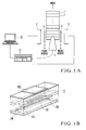
- optical receivers (optical receiving means) 2 and 3 are arranged at the both end of an SOA 1 having a rectangular parallelepiped shape long in the waveguide direction.
- the characteristic evaluation apparatus includes a needle-like probe 4 which can supply the current to the electrode of each of SOAs 1 connected in the shape of a bar.
- the plurality of SOAs 1 connected in the shape of a bar will be referred to as "bar-shaped SOAs 1" hereinafter.
- the bar-shaped SOAs 1 can be formed by cutting them from a wafer such that the plurality of SOAs 1 are continuous in a line in a direction perpendicular to the light incidence end faces.
- Wavelength filters 5 and 6 serving as optical transmission adjustment means are arranged between the optical receivers 2 and 3 and both ends of each of the bar-shaped SOAs 1 so as to be freely inserted or removed.
- the characteristic evaluation apparatus also has a power supply/ammeter 21 which supplies the current to the SOA 1 and indicates the output value from the optical receivers 2 and 3, and a computer 22 which executes various kinds of information processing in measured data by the power supply/ammeter 21.
- the computer 22 is an apparatus which executes wavelength characteristic discrimination, polarization characteristic discrimination, wavelength characteristic estimation, and the like (to be described below) in accordance with a program recorded in advance.
- One of the SOAs 1 has spot size conversion regions 102 at the input and output ends of an active region 101 that executes optical amplification, as shown in, e.g., the perspective view of Fig. 1B, which shows an example of an SOA to be evaluated.
- the current supplied to electrodes 103 and 104 is supplied to the active region 101 whereby an optical signal passing through the active region 101 is amplified.
- the SOA 1 is fixed to a stage (fixing means) (not shown) movable in a predetermined position. This stage is moved in the predetermined position, and the probe is sequentially brought into contact with each of the arrayed SOAs by a probe movement control means (not shown) to supply the current.
- the probe 4 is brought into contact with one of the bar-shaped SOAs 1.
- the wavelength filters 5 and 6 are kept removed.
- the optical outputs from the SOA 1 are detected by the optical receivers 2 and 3.
- the outputs from the optical receivers 2 and 3, which are obtained through the power supply/ammeter 21, are loaded and processed by the computer 22. In this way, the optical output intensity from the SOA 1 is measured.
- the wavelength filters 5 and 6 are kept inserted.
- the optical outputs from the SOA 1 are detected by the optical receivers 2 and 3.
- the outputs from the optical receivers 2 and 3, which are obtained through the power supply/ammeter 21, are read by the computer 22. In this way, the optical output intensity from the SOA 1 is measured.
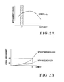
- the optical output intensity from the SOA 1 has a broadband spectrum, as shown in Fig. 2A. For this reason, when the wavelength filters 5 and 6 are kept removed, an intensity obtained by integrating the entire wavelength band shown in Fig. 2A is obtained as the optical output intensity from the SOA 1.
- the wavelength filters 5 and 6 are kept inserted, only the wavelength band of a wavelength ⁇ 1 indicated by the hatched portion in Fig. 2A is transmitted through the wavelength filters 5 and 6 and received by the optical receivers 2 and 3. For this reason, the received optical intensity at this time is lower than the optical output intensity from the SOA 1 when the wavelength filters 5 and 6 are kept removed.
- the optical output intensities when the wavelength filters 5 and 6 are kept inserted and removed increase as the current increases.
- the optical output intensities are uniquely defined. For this reason, it can be discriminated whether the peak wavelength of the SOA 1 is appropriate by checking to which optical output intensity of the SOA 1 the received optical intensity corresponds (the ratio of two data shown in Fig. 2B) (wavelength characteristic discrimination).
- the optical output intensity is defined as a specified value K0.
- the optical output intensity is defined as a specified value K1.
- the received optical intensity is compared with the specified value K0 of a non-defective unit.
- the received optical intensity when the wavelength filters 5 and 6 are kept inserted is compared with the specified value K1 of a non-defective unit.
- the bar-shaped SOAs 1 are moved by a distance corresponding to one element while keeping the probe 4 lifted, and the same process as described above is executed.
- the characteristic of the SOA 1 can be evaluated only by measuring received optical intensities while keeping the wavelength filters 5 and 6 inserted and removed. For this reason, according to this embodiment, no external light injection to the SOA 1 is needed. Accurate fiber coupling to the two ends of the SOA 1 is unnecessary. Hence, the fiber coupling loss and the like can be eliminated, and a sufficient measurement sensitivity can be obtained. As a result, the current can be supplied to the SOA 1 by pulse driving. Mounting on a mount excellent in heat dissipation is unnecessary. Hence, direct evaluation of elements to be mounted in products can be executed. In addition, there has been no need for fiber alignment, and the measurement time can be shortened.
- the SOAs 1 can be handled easily when evaluating their characteristics. Even when all the SOAs 1 are inspected, any increase in measurement time can be suppressed.
- the bar-shaped SOAs 1 When inspecting all the SOAs 1, the bar-shaped SOAs 1 may be moved by a distance corresponding to one element. Instead, the probe 4, optical receivers 2 and 3, and optical filters 5 and 6 may be moved by a distance corresponding to one element.
- the power supply and ammeter are integrated. However, they may be separated. This modification is also applied to all the following embodiments.
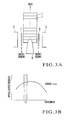
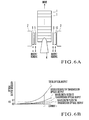
- wavelength filters 7 and 8 are arranged in place of wavelength filters 5 and 6 shown in Fig. 1A as optical transmission adjustment means.
- the transmission range of the wavelength filters 5 and 6 shown in Fig. 1A is ⁇ 1 while that of the wavelength filters 7 and 8 shown in Fig. 3A is changed to ⁇ 2.
- characteristic screening evaluation
- a probe 4 is brought into contact with one element of the bar-shaped SOAs 1.
- the wavelength filters 7 and 8 are kept inserted in place of the wavelength filters 5 and 6.
- the optical outputs from the SOA 1 are detected by the optical receivers 2 and 3. In this way, the optical output intensity from the SOA 1 is measured.
- the optical output intensity from the SOA 1 has a broadband spectrum, as shown in Fig. 3B.
- the wavelength filters 7 and 8 are kept inserted, only the wavelength band of the wavelength ⁇ 2 indicated by the hatched portion in Fig. 3B is transmitted through the wavelength filters 7 and 8 and received by the optical receivers 2 and 3.
- the optical output intensity when the wavelength filters 7 and 8 having a different transmission band are used changes for each transmission band of the wavelength filters 7 and 8.
- the optical output intensity can be defined as a specified value K1.
- the optical output intensity can be defined as a specified value K2.
- the received optical intensity when the wavelength filters 5 and 6 are kept inserted is compared with the specified value K1.
- the received optical intensity when the wavelength filters 7 and 8 are kept inserted is compared with the specified value K2.
- measurement results that are obtained using the wavelength filters 7 and 8 by changing the transmission wavelength to ⁇ 3 and ⁇ 4 are compared with specified values K3 and K4.
- wavelength filters having transmission bands in transmission bands ⁇ 3 and ⁇ 4 are used, the number of optical output intensity measurement points in specific wavelength ranges can be increased.
- the bar-shaped SOAs 1 are moved by a distance corresponding to one element while keeping the probe 4 lifted, and the same process as described above is executed.
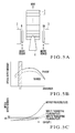
- polarizers 9 and 10 are arranged in place of the wavelength filters 5 and 6 shown in Fig. 1A as optical transmission adjustment means.
- a probe 4 is brought into contact with one element of the bar-shaped SOAs 1.
- the polarizers 9 and 10 are kept inserted.
- the optical output intensity measurement is executed only twice using the polarizers 9 and 10, i.e., by using a TE mode transmission plate first, and then a TM mode transmission plate.
- the optical output intensities of TE mode transmission light and TM mode transmission light of the SOA 1 have broadband spectra, as shown in Fig. 5B.
- the received optical intensities decrease to almost 1/2 of that when the polarizers 9 and 10 are not used, as shown in Fig. 5C.
- the optical output intensities of TE mode transmission light and TM mode transmission light may differ between the modes.
- the intensity difference between the TE mode transmission light and the TM mode transmission light reflects the spectrum difference shown in Fig. 5B.
- the optical output intensity can be defined as a specified value K5.
- the optical output intensity can be defined as a specified value K6.
- Two polarized optical components whose polarization states are perpendicular to each other are measured.
- the difference (measurement value difference) between the TE mode measurement value and the TM mode measurement value and the difference (specified value difference) between the specified value K5 and the specified value K6 are executed.
- the dependence on polarization can also be measured as a characteristic of the SOA.
- the accuracy of characteristic screening of SOAs 1 can be further increased.
- the amplification gain by the SOA 1 is not dependent on polarization.
- the fabrication accuracy and the like of the SOA 1 are taken into consideration, the dependence on polarization remains.
- the received optical intensity measurement process while keeping the polarizers 9 and 10 inserted and removed is added, and the dependence of the SOA 1 on polarization is obtained, the accuracy of characteristic screening of SOAs 1 can be increased without complicating the characteristic screening process.
- the bar-shaped SOAs 1 are moved by a distance corresponding to one element while keeping the probe 4 lifted, and the same process as described above is executed.
- polarizers 9 and 10 are arranged in addition to wavelength filters 5 and 6 shown in Fig. 1A.
- wavelength filters 7 and 8 shown in Fig. 3A may be used.
- a probe 4 is brought into contact with one of the bar-shaped SOAs 1.
- the wavelength filters 5 and 6 are kept inserted.
- the optical output intensities of TE mode transmission light and TM mode transmission light of the SOA 1 have broadband spectra, as shown in Fig. 5B.
- Fig. 5B When the wavelength filters 5 and 6 are kept inserted, only the wavelength band of a wavelength ⁇ 1 indicated by the hatched portion in Fig. 5B is transmitted through the wavelength filters 5 and 6 and received by the optical receivers 2 and 3.
- the optical output intensities of TE mode transmission light and TM mode transmission light change for each transmission band of the wavelength filters 5 and 6.
- the optical output intensity can be defined as a specified value K7.
- the optical output intensity can be defined as a specified value K8.
- the optical output intensity can be defined as a specified value K9.
- the received optical intensity when only the wavelength filters 5 and 6 are inserted is compared with the specified value K7
- the received optical intensity when the wavelength filters 5 and 6 and TE mode transmission plate are inserted is compared with the specified value K8
- the received optical intensity when the wavelength filters 5 and 6 and TM mode transmission plate are inserted is compared with the specified value K9
- the bar-shaped SOAs 1 are moved by a distance corresponding to one element while keeping the probe 4 lifted, and the same process as described above is executed.
- the dependence of the SOA 1 on wavelength or polarization can be measured at once by inserting or removing combinations of the wavelength filters 5 and 6 and polarizers 9 and 10.
- This characteristic evaluation apparatus can easily cope with a number of measurement evaluation items.
- Fig. 7 shows an SOA characteristic evaluation method according to the fifth embodiment of the present invention.
- step S1 SOAs 1 are set in a characteristic evaluation apparatus, and I-L measurement of the SOA 1 is executed without using any wavelength filter (step S1).
- step S2 when a specific current is supplied, the optical output intensity from the SOA 1 is compared with a specified value. Element screening A is thus executed (step S2).
- wavelength filters 5 and 6 are inserted between the end faces of the SOA 1 and optical receiver 2 and between the end faces of the SOA 1 and optical receiver 3, respectively.
- I-L measurement of the SOAs 1 is executed (step S3).
- polarizers 9 and 10 are inserted between the end faces of the SOA 1 and optical receiver 2 and between the end faces of the SOA 1 and optical receiver 3, respectively. Subsequently, I-L measurement of the SOA 1 is executed (step S5). The I-L measurement of the SOA 1 in step S5 is executed only twice using a TE mode transmission plate and TM mode transmission plate as the polarizers 9 and 10.
- the flow returns to step S3.
- the wavelength filters 5 and 6 are exchanged (for example, the wavelength filters 5 and 6 are exchanged with wavelength filters 7 and 8 having a different transmission wavelength range), and measurement is executed. The measurement is repeated while appropriately exchanging the wavelength filters with those prepared for use (steps S3 to S5).
- step S6 the optical output intensity from the SOA 1 when the polarizers 9 and 10 are inserted is compared with each specified value, including optical output intensities in the repeated cycles.
- Element screening C is thus executed (step S6).
- steps S1 and S2 may be executed after steps S3 to S5 are repeated.
- the order of processes is not limited to that shown in Fig. 7.
- evaluation is executed in all steps. However, the steps may appropriately be selected. For example, measurement in step S3 and step S4 may be omitted. After only exchange of wavelength filters is executed in step S3, other steps may be executed for evaluation.
- a method of inserting/removing the wavelength filters 5 to 8 or polarizers 9 and 10 a method of controlling insertion and removal of these optical components by a robot arm, a method of arranging these optical components on a linear rail including space portions without any optical components and controlling to place necessary optical components immediately in front of the optical receivers 2 and 3, or a method of arranging these optical components on a ring-shaped rail including space portions without any optical components and controlling to place necessary optical components immediately in front of the optical receivers 2 and 3 can be used.
- the rail to be used to arrange the components such as the wavelength filters 5 to 8 or polarizers 9 and 10 may be parallel or perpendicular to the horizontal plane.
- the optical output intensity is measured at the two ends of the SOA 1. However, this measurement may be done only at one end of the SOA 1.
- the optical receiver 2 may be arranged only on one side of the SOA 1, and the optical output intensities at the two ends of the SOA 1 may be measured by reversing the SOA 1 in the horizontal direction.
- the characteristic evaluation apparatus may be applied to the SOA 1 having a spot size conversion unit or the SOA 1 having no spot size conversion unit.
- the characteristic evaluation apparatus may also be applied to evaluate the characteristic of an optical element other than the SOA 1, which includes a semiconductor optical emitting element having input and output ends.
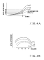
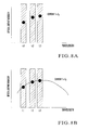
- Fig. 8A plots optical intensities measured using three wavelength filters.
- the transmission center wavelengths of the three wavelength filters are ⁇ 1, ⁇ 2, and ⁇ 3, respectively.
- the transmission bands are indicated by hatched portions in Fig. 8A.
- Fig. 8B shows a result obtained by executing parameter fitting based on equation (8) to approximate the optical intensities. A result that satisfactorily coincides with the measurement result was obtained, and the effect of the measurement method according to this embodiment was confirmed.
- Equation (1) An optical output intensity P ASE ( ⁇ ) transmitted through a filter at a wavelength ⁇ is given by equation (1). Derivation of equation (1) is described in detail in known reference, N.A. Olsson, "IEEE J. Lightwave Technol.”, vol. 8, pp. 1081-1082, 1989.
- P ASE ( ⁇ ) (G lin ( ⁇ ) - 1) ⁇ n sp ⁇ E ⁇ ⁇
- G lin ( ⁇ ) is the gain
- n sp the spontaneous emission coefficient
- E h ⁇ ⁇ is the photon energy (h: Planck constant, ⁇ : frequency)
- ⁇ ⁇ is the bandwidth to be considered.
- An optical output intensity P filtering ASE ( ⁇ 0 ) passing through a filter which is obtained by the measurement method according to this embodiment, corresponds to a value obtained by integrating equation (1) by a center wavelength ⁇ 0 across a filter band ⁇ f .
- E and G lin ( ⁇ ) are functions of the frequency ⁇ (i.e., wavelength ⁇ ).
- the physical quantity represented by equation (4) can be defined as the virtual optical input. Then a gain G lin ( ⁇ 0 ) can be obtained using the optical output intensity passing through the filter P filtering ASE ( ⁇ 0 ) and the virtual optical input.
- P ASE-input ( ⁇ 0 ) hc 2 n sp ⁇ ⁇ f ⁇ 3 0
- G dB ( ⁇ 0 ) 10 ⁇ log(G lin ( ⁇ 0 )).
- P dB-filtering ASE ( ⁇ 0 ) G dB ( ⁇ 0 )+P dB ASE-input ( ⁇ 0 )
- a value P dB ASE-iuput ( ⁇ 0 ) is set on the basis of equation (6).
- a measured value P dB-filtering ASE ( ⁇ 0 ) and a value G dB ( ⁇ 0 ) calculated from equation (7) it is possible to execute chip screening whether the values agree within the set data range or not. Screening is thus executed.
- Equation (7) indicates that when the value P dB-filtering ASE ( ⁇ 0 ) is obtained by measurement, and the value P dB ASE-input ( ⁇ 0 ) as virtual input light is calculated on the basis of equation (6), the gain characteristic G dB ( ⁇ 0 ) can be obtained as the difference between the values.
- measuring the transmission optical output P dB-filtering ASE ( ⁇ 0 ) of the wavelength filter is equivalent to measuring the gain characteristic.
- the optical output is used in place of the gain as the characteristic of the SOA.
- equation (7) is taken into consideration, it is almost equivalent to measuring the gain characteristic.
- the value p dB-filtering ASE ( ⁇ 0 ) is represented as the function of ⁇ 0 .
- the dependence on ⁇ 0 is very small.
- the value P dB-filtering ASE ( ⁇ 0 ) can almost be regarded as a constant.
- the shape of gain spectrum is not described.
- a number of wavelength filters must be prepared at a small wavelength interval.
- the gain peak wavelength largely deviates from the center wavelengths of prepared wavelength filters, the evaluation/screening accuracy degrades.
- the measurement method according to this embodiment includes a correction effect for such a wavelength deviation.
- G dB peak is the peak gain
- ⁇ p the peak wavelength when the peak gain is obtained
- ⁇ is the half-width.
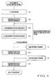
- Fig. 9 is a flow chart of the characteristic evaluation screening method (SOA characteristic evaluation method) according to the sixth embodiment of the present invention. This will be described with reference to Fig. 6.
- SOAs 1 are set in the characteristic evaluation apparatus. The current is supplied from a probe 4. The optical output intensities from the end faces of an SOA 1 are detected by optical receivers 2 and 3. In this way, the current vs. optical output (I-L) characteristic is measured (step S11). The optical output intensity of the SOA 1 is compared with each specified value. Element screening A is thus executed (step S12).
- wavelength filters 5 and 6 are inserted between the end faces of the SOA 1 and optical receiver 2 and between the end faces of the SOA 1 and optical receiver 3, respectively. Subsequently, the current vs. optical output (I-L) characteristic of the SOA 1 is measured (step S13).
- step S14 the I-L characteristic of the SOA 1 for each polarization is measured.
- the measurement in step S14 is executed twice as the polarizers 9 and 10 pass TE mode transmission light and TM mode transmission light.
- the wavelength filters 5 and 6 are exchanged (for example, exchanged to wavelength filters 7 and 8 having a different transmission wavelength range), and measurement is executed. The measurement is repeated while appropriately exchanging the wavelength filters with those prepared for use. After that, the optical output intensity of the SOA 1 when the wavelength filters are inserted is compared with each specified value. Element screening B is thus executed (step S15).
- step S16 the optical output intensity of the SOA 1 when the polarizers 9 and 10 are inserted is compared with the specified value for each polarization.
- Element screening C is thus executed (step S16).
- parameter fitting is executed on the basis of equations (7) and (8) using optical intensities measured for three or more wavelength filters.
- the gain characteristic is estimated for each polarized wave component (step T1).
- a step of estimating the gain characteristic for each polarized wave component is added (wavelength characteristic estimation).
- the step S12 by the I-L characteristic, the step S15 by the I-L characteristic with wavelength filters, and the step S16 by the polarizers 9 and 10 are prepared.
- related evaluation and screening may be executed using only desired steps by appropriately selecting them.
- Evaluation and screening may also be executed using a desired one of steps T1 and T2 by appropriately selecting it.
- An external function for executing FFP measurement may be added. Note that, for example, steps S11 and S12 may be executed after steps S13 and S14 are repeated. The order of steps is not limited to that shown in Fig. 9.
- the number of wavelength filters to be inserted or removed and the types and number of polarizers 9 and 10 are not particularly limited.
- At least three wavelength filters having different transmission wavelengths are used.
- Optical outputs from the SOA 1 when the wavelength filters are inserted or removed are measured for each wavelength filter. On the basis of the measurement results, the wavelength characteristic of the gain of the SOA 1 is estimated.
- the wavelength characteristic of the gain of the SOA 1 can be grasped without executing measurement for a number of wavelengths.
- the fact that the gain peak wavelength largely deviates from the expected center wavelength can be specified to some extent. Hence, even when defects are generated, the reason for the degradation caused in evaluation/screening results may be clarified.
- At least three wavelength filters having different transmission wavelengths are used.
- optical outputs from the SOA 1 are measured while keeping the wavelength filters inserted and the polarizers 9 and 10 inserted or removed.
- the wavelength characteristic of the gain of the SOA 1 is estimated for each polarized optical component.
- the wavelength characteristic of the gain of the SOA 1 for each polarized optical component can be grasped without executing measurement for a number of wavelengths.
- the reason that the gain peak wavelength largely deviates from the center wavelength of a wavelength filter can be specified to some extent. Hence, even when defects are generated, the reason for the degradation caused in evaluation/screening results may be clarified.
- current supply to the SOA 1 may be done either by pulse driving or by CW driving.
- an optical output generated by an SOA is measured by an optical receiver, and the characteristic of the SOA is evaluated on the basis of the measurement result. Accordingly, the characteristic screening of SOAs can be executed without making external light incident on the SOAs. For example, it can be discriminated on the basis of the optical output intensity from an SOA while keeping wavelength filters inserted or removed whether the gain and gain spectrum of the SOA at a specific wavelength are appropriate. Hence, for example, even when pulse driving is executed, a sufficient measurement sensitivity can be ensured.
- the evaluation chip in evaluating an SOA, no fiber coupling to the two ends of the SOA is needed to eliminate the fiber coupling loss.
- the evaluation chip can be directly used for a product.
Landscapes
- Physics & Mathematics (AREA)
- Electromagnetism (AREA)
- Engineering & Computer Science (AREA)
- Computer Networks & Wireless Communication (AREA)
- Signal Processing (AREA)
- Semiconductor Lasers (AREA)
- Testing Of Optical Devices Or Fibers (AREA)
Applications Claiming Priority (4)
| Application Number | Priority Date | Filing Date | Title |
|---|---|---|---|
| JP2001310426 | 2001-10-05 | ||
| JP2001310426 | 2001-10-05 | ||
| JP2002268796 | 2002-09-13 | ||
| JP2002268796A JP3863084B2 (ja) | 2001-10-05 | 2002-09-13 | 半導体光増幅器の特性選別方法およびその装置 |
Publications (3)
| Publication Number | Publication Date |
|---|---|
| EP1300967A2 true EP1300967A2 (fr) | 2003-04-09 |
| EP1300967A3 EP1300967A3 (fr) | 2004-07-07 |
| EP1300967B1 EP1300967B1 (fr) | 2005-04-06 |
Family
ID=26623784
Family Applications (1)
| Application Number | Title | Priority Date | Filing Date |
|---|---|---|---|
| EP02090349A Expired - Lifetime EP1300967B1 (fr) | 2001-10-05 | 2002-10-04 | Procédé d' évaluation d'un amplificateur optique à semiconducteur et instrument d'évaluation |
Country Status (4)
| Country | Link |
|---|---|
| US (1) | US6728025B2 (fr) |
| EP (1) | EP1300967B1 (fr) |
| JP (1) | JP3863084B2 (fr) |
| DE (1) | DE60203578T2 (fr) |
Families Citing this family (6)
| Publication number | Priority date | Publication date | Assignee | Title |
|---|---|---|---|---|
| JP4622216B2 (ja) * | 2003-08-21 | 2011-02-02 | 横河電機株式会社 | 光スペクトラムアナライザ |
| US7256879B2 (en) * | 2003-12-11 | 2007-08-14 | Corning Incorporated | Semiconductor array tester |
| US9634463B2 (en) * | 2014-07-09 | 2017-04-25 | Sumitomo Electric Device Innovations, Inc. | Optical module installing a semiconductor optical amplifier and process of assembling the same |
| JP2016018121A (ja) * | 2014-07-09 | 2016-02-01 | 住友電工デバイス・イノベーション株式会社 | 光増幅モジュールを製造する方法 |
| JP6998719B2 (ja) * | 2017-10-06 | 2022-01-18 | 古河電気工業株式会社 | 半導体光増幅器の評価方法 |
| CN121192502B (zh) * | 2025-11-25 | 2026-02-27 | 成都讯速信远科技有限公司 | 基于智能判决的dfb激光器芯片光电探针耦合方法及系统 |
Family Cites Families (8)
| Publication number | Priority date | Publication date | Assignee | Title |
|---|---|---|---|---|
| JPH01132976A (ja) * | 1987-11-17 | 1989-05-25 | Mitsubishi Electric Corp | 半導体レーザ検査方法及びその検査装置 |
| EP0716515B1 (fr) * | 1994-12-02 | 1999-08-04 | Hewlett-Packard GmbH | Arrangement pour générer des signaux optiques avec différentes longueurs et arrangement et procédé pour opérer et tester un dispositif optique |
| JP3272934B2 (ja) * | 1996-02-07 | 2002-04-08 | 安藤電気株式会社 | 波長多重光増幅器の評価測定装置および方法 |
| JPH10160785A (ja) * | 1996-11-29 | 1998-06-19 | Nippon Telegr & Teleph Corp <Ntt> | 半導体レーザの選別方法及びその装置 |
| JP2000068602A (ja) * | 1998-08-21 | 2000-03-03 | Nippon Telegr & Teleph Corp <Ntt> | 光増幅利得測定装置 |
| US6587261B1 (en) * | 1999-05-24 | 2003-07-01 | Corvis Corporation | Optical transmission systems including optical amplifiers and methods of use therein |
| JP2001308417A (ja) * | 2000-04-18 | 2001-11-02 | Ando Electric Co Ltd | 光増幅器評価方法および光増幅器評価装置 |
| JP2002055022A (ja) * | 2000-08-08 | 2002-02-20 | Nippon Telegr & Teleph Corp <Ntt> | 半導体光素子特性評価装置 |
-
2002
- 2002-09-13 JP JP2002268796A patent/JP3863084B2/ja not_active Expired - Fee Related
- 2002-10-02 US US10/263,233 patent/US6728025B2/en not_active Expired - Fee Related
- 2002-10-04 DE DE60203578T patent/DE60203578T2/de not_active Expired - Lifetime
- 2002-10-04 EP EP02090349A patent/EP1300967B1/fr not_active Expired - Lifetime
Also Published As
| Publication number | Publication date |
|---|---|
| JP3863084B2 (ja) | 2006-12-27 |
| US20030099033A1 (en) | 2003-05-29 |
| US6728025B2 (en) | 2004-04-27 |
| EP1300967B1 (fr) | 2005-04-06 |
| DE60203578D1 (de) | 2005-05-12 |
| DE60203578T2 (de) | 2006-02-09 |
| EP1300967A3 (fr) | 2004-07-07 |
| JP2003177075A (ja) | 2003-06-27 |
Similar Documents
| Publication | Publication Date | Title |
|---|---|---|
| Baney et al. | Theory and measurement techniques for the noise figure of optical amplifiers | |
| US7256879B2 (en) | Semiconductor array tester | |
| Dawson et al. | An improved delayed self-heterodyne interferometer for linewidth measurements | |
| EP0678988B1 (fr) | Méthode de mesure du niveau de bruit en présence d'un signal | |
| EP0762677A2 (fr) | Système de communication, optique déterminant le spectre d'un signal multiplexé par longueur d'onde et exécutant diverses opérations en fonction du spectre déterminé | |
| US8693512B2 (en) | Frequency referencing for tunable lasers | |
| EP0921614B1 (fr) | Source laser à large bande de puissance et à bruit faible | |
| CN105281827B (zh) | 掺铒光纤放大器实时检测系统 | |
| EP0586103B1 (fr) | Mesure d'un paramètre d'un amplificateur optique | |
| US8477411B2 (en) | Fiber-adaptive distributed Raman amplifier pump setup scheme | |
| EP1130815A2 (fr) | Récepteur hétérodyne optique en diversité de polarisation et sélectif en longeur d'onde | |
| US20040161242A1 (en) | Method and apparatus for monitoring channel performance in dense wavelength division multiplexed (DWDM) optical networks | |
| US6256103B1 (en) | System and method for optical heterodyne detection of an optical signal | |
| EP1300967B1 (fr) | Procédé d' évaluation d'un amplificateur optique à semiconducteur et instrument d'évaluation | |
| US6535289B1 (en) | System and method for optical heterodyne detection of an optical signal | |
| US20030147126A1 (en) | Method and device for regulating a medium with an amplifying effect, especially a fiber optical waveguide | |
| JP2746354B2 (ja) | 固定検光子を用いた偏波モード分散測定方法及び装置 | |
| US6731381B2 (en) | Method and apparatus to measure gain spectra of erbium doped fiber amplifier | |
| JP3403643B2 (ja) | 偏波依存性精密測定機器 | |
| JP4202821B2 (ja) | 反射型半導体光増幅器の特性評価方法 | |
| US6751012B1 (en) | Method and apparatus for measuring noise figure in optical amplifiers | |
| JP2000216458A (ja) | 光ファイバ増幅器の増幅特性測定装置 | |
| JP2000068602A (ja) | 光増幅利得測定装置 | |
| JPH0730178A (ja) | 光ファイバ増幅器および光ファイバ増幅器の増幅特性測定装置 | |
| Kinoshita et al. | Optimized bandwidth of optical filter in optical preamplifier |
Legal Events
| Date | Code | Title | Description |
|---|---|---|---|
| PUAI | Public reference made under article 153(3) epc to a published international application that has entered the european phase |
Free format text: ORIGINAL CODE: 0009012 |
|
| AK | Designated contracting states |
Designated state(s): AT BE BG CH CY CZ DE DK EE ES FI FR GB GR IE IT LI LU MC NL PT SE SK TR Kind code of ref document: A2 Designated state(s): AT BE BG CH CY CZ DE DK EE ES FI FR GB GR IE IT LI LU MC NL PT SE SK TR |
|
| AX | Request for extension of the european patent |
Extension state: AL LT LV MK RO SI |
|
| PUAL | Search report despatched |
Free format text: ORIGINAL CODE: 0009013 |
|
| AK | Designated contracting states |
Kind code of ref document: A3 Designated state(s): AT BE BG CH CY CZ DE DK EE ES FI FR GB GR IE IT LI LU MC NL PT SE SK TR |
|
| AX | Request for extension of the european patent |
Extension state: AL LT LV MK RO SI |
|
| 17P | Request for examination filed |
Effective date: 20040712 |
|
| GRAP | Despatch of communication of intention to grant a patent |
Free format text: ORIGINAL CODE: EPIDOSNIGR1 |
|
| GRAS | Grant fee paid |
Free format text: ORIGINAL CODE: EPIDOSNIGR3 |
|
| GRAA | (expected) grant |
Free format text: ORIGINAL CODE: 0009210 |
|
| AKX | Designation fees paid |
Designated state(s): DE FR GB |
|
| AK | Designated contracting states |
Kind code of ref document: B1 Designated state(s): DE FR GB |
|
| REG | Reference to a national code |
Ref country code: GB Ref legal event code: FG4D |
|
| REG | Reference to a national code |
Ref country code: IE Ref legal event code: FG4D |
|
| REF | Corresponds to: |
Ref document number: 60203578 Country of ref document: DE Date of ref document: 20050512 Kind code of ref document: P |
|
| ET | Fr: translation filed | ||
| PLBE | No opposition filed within time limit |
Free format text: ORIGINAL CODE: 0009261 |
|
| STAA | Information on the status of an ep patent application or granted ep patent |
Free format text: STATUS: NO OPPOSITION FILED WITHIN TIME LIMIT |
|
| 26N | No opposition filed |
Effective date: 20060110 |
|
| PGFP | Annual fee paid to national office [announced via postgrant information from national office to epo] |
Ref country code: GB Payment date: 20140910 Year of fee payment: 13 |
|
| PGFP | Annual fee paid to national office [announced via postgrant information from national office to epo] |
Ref country code: DE Payment date: 20141029 Year of fee payment: 13 |
|
| PGFP | Annual fee paid to national office [announced via postgrant information from national office to epo] |
Ref country code: FR Payment date: 20141027 Year of fee payment: 13 |
|
| REG | Reference to a national code |
Ref country code: DE Ref legal event code: R119 Ref document number: 60203578 Country of ref document: DE |
|
| GBPC | Gb: european patent ceased through non-payment of renewal fee |
Effective date: 20151004 |
|
| PG25 | Lapsed in a contracting state [announced via postgrant information from national office to epo] |
Ref country code: DE Free format text: LAPSE BECAUSE OF NON-PAYMENT OF DUE FEES Effective date: 20160503 Ref country code: GB Free format text: LAPSE BECAUSE OF NON-PAYMENT OF DUE FEES Effective date: 20151004 |
|
| REG | Reference to a national code |
Ref country code: FR Ref legal event code: ST Effective date: 20160630 |
|
| PG25 | Lapsed in a contracting state [announced via postgrant information from national office to epo] |
Ref country code: FR Free format text: LAPSE BECAUSE OF NON-PAYMENT OF DUE FEES Effective date: 20151102 |