EP1301825B1 - Kamerasystem mit mindestens zwei ersten und zweiten kameras - Google Patents
Kamerasystem mit mindestens zwei ersten und zweiten kameras Download PDFInfo
- Publication number
- EP1301825B1 EP1301825B1 EP01969338A EP01969338A EP1301825B1 EP 1301825 B1 EP1301825 B1 EP 1301825B1 EP 01969338 A EP01969338 A EP 01969338A EP 01969338 A EP01969338 A EP 01969338A EP 1301825 B1 EP1301825 B1 EP 1301825B1
- Authority
- EP
- European Patent Office
- Prior art keywords
- cameras
- camera system
- optical axes
- axis
- symmetry
- Prior art date
- Legal status (The legal status is an assumption and is not a legal conclusion. Google has not performed a legal analysis and makes no representation as to the accuracy of the status listed.)
- Expired - Lifetime
Links
- 230000003287 optical effect Effects 0.000 claims abstract description 9
- 238000007373 indentation Methods 0.000 claims 1
- 230000000007 visual effect Effects 0.000 abstract description 2
- 230000001419 dependent effect Effects 0.000 description 1
- 238000011156 evaluation Methods 0.000 description 1
- 238000003384 imaging method Methods 0.000 description 1
Images
Classifications
-
- G—PHYSICS
- G01—MEASURING; TESTING
- G01C—MEASURING DISTANCES, LEVELS OR BEARINGS; SURVEYING; NAVIGATION; GYROSCOPIC INSTRUMENTS; PHOTOGRAMMETRY OR VIDEOGRAMMETRY
- G01C11/00—Photogrammetry or videogrammetry, e.g. stereogrammetry; Photographic surveying
- G01C11/02—Picture taking arrangements specially adapted for photogrammetry or photographic surveying, e.g. controlling overlapping of pictures
-
- G—PHYSICS
- G03—PHOTOGRAPHY; CINEMATOGRAPHY; ANALOGOUS TECHNIQUES USING WAVES OTHER THAN OPTICAL WAVES; ELECTROGRAPHY; HOLOGRAPHY
- G03B—APPARATUS OR ARRANGEMENTS FOR TAKING PHOTOGRAPHS OR FOR PROJECTING OR VIEWING THEM; APPARATUS OR ARRANGEMENTS EMPLOYING ANALOGOUS TECHNIQUES USING WAVES OTHER THAN OPTICAL WAVES; ACCESSORIES THEREFOR
- G03B37/00—Panoramic or wide-screen photography; Photographing extended surfaces, e.g. for surveying; Photographing internal surfaces, e.g. of pipe
- G03B37/04—Panoramic or wide-screen photography; Photographing extended surfaces, e.g. for surveying; Photographing internal surfaces, e.g. of pipe with cameras or projectors providing touching or overlapping fields of view
Definitions
- the invention relates to a camera system for photogrammetric applications and for applications in air reconnaissance.
- DE 44 20 422 A1 describes a technical complex eye for dynamic, machine vision, in particular for vehicles, with a two-axis rotatable and controllable platform on which three or more imaging sensors are arranged, wherein two wide-angle cameras are arranged on the platform, that their optical axes diverge in the direction of the visual axis of the complex eye and their viewing areas overlap in front of the platform, and wherein a telecamera is aligned with the area in which the viewing areas of the wide-angle cameras overlap.
- a second telecamera can be provided.
- the camera system has at least two first cameras, each having its own lens, the optical axes are arranged inclined to each other.
- the camera system also has at least two additional cameras in Viewing direction of the first cameras are arranged offset to these first cameras.
- the first cameras are panchromatic digital cameras, which capture the terrain to be surveyed with high lateral resolution, but without color information.
- the second cameras are designed as multichromatic digital cameras, which also records the color information of the overflown terrain, albeit at a lower lateral resolution. For the later photogrammetric evaluation of the image information recorded with the camera system, all aperture cones of the first and second cameras have a common, central, overlapping region.
- At least three first cameras are arranged symmetrically with respect to an axis of symmetry, and the second cameras are arranged offset in the direction of this symmetry axis relative to the first cameras.
- a total of four first cameras are arranged symmetrically to an axis of symmetry.
- Four cameras can be used to achieve a high image coverage, ie a large, simultaneously recorded angle range.
- second cameras are also provided, which are also arranged symmetrically to the axis of symmetry of the first cameras.
- the optical axes of the second cameras can be aligned parallel to each other.
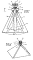
- the camera system in FIGS. 1 and 2 has four first cameras (1, 2, 12, 13) and four second cameras (10, 11, 14), the second cameras (10, 11, 14) looking in the direction of view the first cameras (1,2,12,13) offset from the first cameras (1,2,12,13) are arranged.
- Each of these four first and second cameras contains a housing, an objective accommodated on each housing and a CCD image sensor arranged behind the respective objective.
- the image sensors, not shown, of the first cameras (1, 2, 12, 13) are designed as panchromatic CCD image sensors with the highest lateral resolution.
- the CCD sensors of the second cameras (14,15,16) are designed as high-resolution color camera chips.
- the entire camera system still has a fourth second camera, which is not shown in the perspective view of Figure 2, since it is covered by one of the first cameras (12).
- the four first cameras (1,2,12,13) are arranged symmetrically to an axis of symmetry (9).
- the first cameras (1, 2, 12, 13) are arranged mutually inclined relative to the symmetry axis (9) by equal angular amounts relative to one another, so that the optical axes (7, 8) of the first cameras are in a common intersection (5). which lies on the symmetry axis (9) intersect.
- the diameter of the aperture cone of the first cameras (1,2) envelope is constant.
- the second cameras (10,11) are arranged such that through the housing of the second cameras (10,11) Opening cone of the first cameras (1,2) can not be cropped.
- the support structure (6) for the second cameras (10, 11) has a correspondingly large opening for the free passage of the opening cones of the first cameras.
- optical axes (17,18) of the second cameras (10,11) are aligned parallel to the axis of symmetry (9).
- the objectives (3,4) of the first cameras are designed so that each of the first cameras takes a picture angle of at least 20 °.
- the relative inclination of the first cameras to each other is selected so that all first cameras collectively detect an angle of view of about 40 ° in two mutually perpendicular directions perpendicular to the axis of symmetry (9).
- the lenses of the second cameras (10,11) are designed so that all the other cameras collectively capture an angle of view of about 50 ° in two mutually perpendicular directions perpendicular to the axis of symmetry (9).
- the camera system By the camera system according to the present invention, an optimally compact arrangement of the individual cameras is achieved.
- the combined field of view of both the first cameras and the second cameras thereby ensures 100% ground coverage, i.e. there is no unrecognized angular range between the individual opening cones.
- the inventive arrangement of the cameras also ensures high stability in terms of vibration and temperature behavior due to short distances between the individual cameras.
- the distances between the first cameras are greater than the distances of the second cameras with each other in the described arrangement.
Landscapes
- Physics & Mathematics (AREA)
- General Physics & Mathematics (AREA)
- Engineering & Computer Science (AREA)
- Multimedia (AREA)
- Radar, Positioning & Navigation (AREA)
- Remote Sensing (AREA)
- Studio Devices (AREA)
- Stereoscopic And Panoramic Photography (AREA)
- Cameras In General (AREA)
- Testing, Inspecting, Measuring Of Stereoscopic Televisions And Televisions (AREA)
Description
- Die Erfindung betrifft ein Kamerasystem für photogrammetrische Anwendungen sowie für Anwendungen in der Luftaufklärung.
- Die DE 44 20 422 A1 beschreibt ein technisches Komplexauge für dynamisches, maschinelles Sehen, insbesondere für Fahrzeuge, mit einer um zwei Achsen drehbaren und steuerbaren Plattform, auf der drei oder mehrere abbildende Sensoren angeordnet sind, wobei auf der Plattform zwei Weitwinkelkameras derart angeordnet sind, dass ihre optischen Achsen in Richtung der Sichtachse des Komplexauges divergieren und sich ihre Sichtbereiche vor der Plattform überlappen und wobei eine Telekamera auf den Bereich ausgerichtet ist, in dem sich die Sichtbereiche der Weitwinkelkameras überlappen. Dabei kann auch eine zweite Telekamera vorgesehen sein.
- Sowohl in der Photogrammetrie als auch in der Luftaufklärung werden zunehmend digitale Kameras eingesetzt. Dabei besteht einerseits der Wunsch nach hoher Ortsauflösung der aufzunehmenden Bilder und andererseits der Wunsch nach Aufnahme von Farbinformation. Maximale Ortsauflösung ist gegenwärtig mit panchromatischen Kameras, die letztendlich nur die Aufzeichnung von schwarz-weiß-Information ermöglichen, erreichbar.
- Da weiterhin der für das gesamte Kamerasystem in Flugzeugen zur Verfügung stehende Bauraum begrenzt ist, besteht der Wunsch nach einer kompakten Anordnung mehrerer Kameras.
- Diesen Bedürfnissen wird die vorliegende Erfindung durch ein Kamerasystem mit den Merkmalen des Anspruches 1 gerecht. Vorteilhafte Ausgestaltungen der Erfindung ergeben sich aus den Merkmalen der abhängigen Ansprüche.
- Das erfindungsgemäße Kamerasystem weist mindestens zwei erste Kameras auf, die jeweils ein eigenes Objektiv aufweisen, deren optische Achsen geneigt zueinander angeordnet sind. Das Kamerasystem weist weiterhin mindestens zwei weitere Kameras auf, die in Blickrichtung der ersten Kameras zu diesen ersten Kameras versetzt angeordnet sind. Die ersten Kameras sind dabei panchromatische digitale Kameras, durch die die Aufnahme des zu vermessenden Geländes mit hoher lateraler Auflösung, jedoch ohne Farbinformation erfolgt. Die zweiten Kameras sind als multichromatische digitale Kameras ausgelegt, durch die auch die Farbinformation des überflogenen Geländes, wenn auch mit geringerer lateraler Auflösung, aufgezeichnet wird. Für die spätere photogrammetrische Auswertung der mit dem Kamerasystem aufgezeichneten Bildinformation weisen sämtliche Öffnungskegel der ersten und zweiten Kameras einen gemeinsamen, zentralen, überlappenden Bereich auf.
- Bei einem vorteilhaften Ausfiihrungsbeispiel sind mindestens drei erste Kameras symmetrisch zu einer Symmetrieachse angeordnet und die zweiten Kameras in Richtung dieser Symmetrieachse versetzt zu den ersten Kameras angeordnet.
- Besonders vorteilhaft sind insgesamt vier erste Kameras symmetrisch zu einer Symmetrieachse angeordnet. Durch vier Kameras läßt sich eine hohe Bildabdeckung, also ein großer simultan erfaßter Winkelbereich erzielen.
- Weiterhin vorzugsweise sind auch vier zweite Kameras vorgesehen, die ebenfalls symmetrisch zur Symmetrieachse der ersten Kameras angeordnet sind. Die optischen Achsen der zweiten Kameras können dabei parallel zueinander ausgerichtet sein.
- Weitere Einzelheiten der Erfindung werden nachfolgend anhand des in den Figuren dargestellten Ausfbhrungsbeispiels näher erläutert. Dabei zeigen:
- Figur 1
- ein erfindungsgemäßes Kamerasystem im Schnitt und
- Figur 2
- eine perspektivische Darstellung des Kamerasystems aus Figur 1.
- Das Kamerasystem in den Figuren 1 und 2 weist vier erste Kameras (1,2,12,13) und vier zweite Kameras (10,11,14) auf, wobei die zweiten Kameras (10,11,14) in Blickrichtung der ersten Kameras (1,2,12,13) versetzt zu den ersten Kameras (1,2,12,13) angeordnet sind. Jede dieser vier ersten und zweiten Kameras enthält dabei ein Gehäuse, ein an jedem Gehäuse aufgenommenes Objektiv und einen hinter dem jeweiligen Objektiv angeordneten CCD-Bildsensor. Die nicht dargestellten Bildsensoren der ersten Kameras (1,2,12,13) sind dabei als panchromatische CCD-Bildsensoren mit höchster lateraler Auflösung ausgelegt. Die CCD-Sensoren der zweiten Kameras (14,15,16) sind als hochauflösende Farbkamerachips ausgebildet.
- An dieser Stelle sei darauf hingewiesen, daß das gesamte Kamerasystem noch eine vierte zweite Kamera aufweist, die in der perspektivischen Darstellung der Figur 2 nicht dargestellt ist, da sie von einer der ersten Kameras (12) verdeckt ist.
- Die vier ersten Kameras (1,2,12,13) sind zu einer Symmetrieachse (9) symmetrisch angeordnet. Die ersten Kameras (1,2,12,13) sind dabei zueinander und relativ zur Symmetrieachse (9) um gleiche Winkelbeträge geneigt zueinander angeordnet, so daß sich die optischen Achsen (7,8) der ersten Kameras in einem gemeinsamen Schnittpunkt (5), der auf der Symmetrieachse (9) liegt, schneiden.
- Durch die zueinander geneigte Anordnung der ersten Kameras (1,2) entsteht unmittelbar vor den Objektiven (3,4) der ersten Kameras ein Bereich (b), in dem die die Öffnungskegel der ersten Kameras kleinste Einhüllende eine Einschnürung in Lateralrichtung, also in Richtung senkrecht zur Symmetrieachse (9), aufweist. In diesem Bereich (b) ist der Durchmesser der die Öffnungskegel der ersten Kameras (1,2) Einhüllenden konstant. In diesem Bereich, in dem die die Öffnungskegel der ersten Kameras (1,2) Einhüllende einen im wesentlichen konstanten Durchmesser aufweist, sind die zweiten Kameras (10,11) derart angeordnet, daß durch die Gehäuse der zweiten Kameras (10,11) die Öffnungskegel der ersten Kameras (1,2) nicht beschnitten werden. Die Tragstruktur (6) für die zweiten Kameras (10,11) weist dazu eine entsprechend große Öffnung für den freien Durchtritt der Öffnungskegel der ersten Kameras auf.
- Die optischen Achsen (17,18) der zweiten Kameras (10,11) sind parallel zur Symmetrieachse (9) ausgerichtet.
- In einem zentralen Bereich (19) überlappen die Öffnungskegel sämtlicher ersten Kameras (1,2) und zweiten Kameras (10,11).
- Die Objektive (3,4) der ersten Kameras sind so ausgelegt, daß jede der ersten Kameras einen Bildwinkel von mindestens 20° aufnimmt. Die relative Neigung der ersten Kameras zueinander ist so gewählt, daß alle ersten Kameras gemeinsam einen Bildwinkel von über 40° in zwei zueinander senkrechten Richtungen senkrecht zur Symmetrieachse (9) erfassen.
- Die Objektive der zweiten Kameras (10,11) sind so ausgelegt, daß alle zweiten Kameras gemeinsam einen Bildwinkel von über 50° in zwei zueinander senkrechten Richtungen senkrecht zur Symmetrieachse (9) erfassen.
- Durch das Kamerasystem gemäß der vorliegenden Erfindung wird eine optimal kompakte Anordnung der einzelnen Kameras erreicht. Das vereinigte Sehfeld sowohl der ersten Kameras als auch der zweiten Kameras gewährleistet dabei eine hundertprozentige Bodenabdeckung, d.h., zwischen den einzelnen Öffnungskegeln existiert kein nicht erfaßter Winkelbereich.
- Wegen der kompakten Bauweise und dem dadurch resultierenden geringen Platzbedarf gewährleistet die erfindungsgemäße Anordnung der Kameras auch eine hohe Stabilität hinsichtlich Schwingungen und Temperaturverhalten in Folge kurzer Abstände der einzelnen Kameras untereinander.
- Die Abstände der ersten Kameras untereinander sind bei der beschriebenen Anordnung größer als die Abstände der zweiten Kameras untereinander.
Claims (6)
- Kamerasystem mit mindestens zwei ersten digitalen panchromatischen Kameras, die jeweils ein eigenes Objektiv aufweisen, deren optische Achsen geneigt zueinander angeordnet sind und mit mindestens zwei zweiten digitalen multichromatischen Kameras, die in Richtung der Blickrichtung der ersten Kameras im Abstand von den ersten Kameras angeordnet sind, wobei die zweiten Kameras in einem Bereich angeordnet sind, in dem die die Öffnungskegel der ersten Kameras kleinste Einhüllende eine Einschnürung oder einen Bereich konstanten Durchmessers aufweist, und wobei die Öffnungskegel der ersten und zweiten Kameras einen gemeinsamen überlappenden Bereich aufweisen.
- Kamerasystem nach Anspruch 1, wobei mindestens drei erste Kameras symmetrisch zu einer Symmetrieachse angeordnet sind und die zweiten Kameras in Richtung dieser Symmetrieachse versetzt zu den ersten Kameras angeordnet sind.
- Kamerasystem nach Anspruch 2, wobei mindestens vier erste Kameras vorgesehen sind.
- Kamerasystem nach einem der Ansprüche 1 - 3, wobei vier zweite Kameras vorgesehen sind.
- Kamerasystem nach Anspruch 2, 3 oder 4, wobei die zweiten Kameras symmetrisch zur Symmetrieachse der ersten Kameras angeordnet sind.
- Kamerasystem nach einem der Ansprüche 1 - 5, wobei die optischen Achsen der Objektive der zweiten Kameras parallel zueinander ausgerichtet sind.
Applications Claiming Priority (3)
| Application Number | Priority Date | Filing Date | Title |
|---|---|---|---|
| DE10034601A DE10034601B4 (de) | 2000-07-14 | 2000-07-14 | Kamerasystem mit mindestens zwei ersten und zweiten Kameras |
| DE10034601 | 2000-07-14 | ||
| PCT/EP2001/007693 WO2002006892A2 (de) | 2000-07-14 | 2001-07-05 | Kamerasystem mit mindestens zwei ersten und zweiten kameras |
Publications (2)
| Publication Number | Publication Date |
|---|---|
| EP1301825A2 EP1301825A2 (de) | 2003-04-16 |
| EP1301825B1 true EP1301825B1 (de) | 2007-03-21 |
Family
ID=7649139
Family Applications (1)
| Application Number | Title | Priority Date | Filing Date |
|---|---|---|---|
| EP01969338A Expired - Lifetime EP1301825B1 (de) | 2000-07-14 | 2001-07-05 | Kamerasystem mit mindestens zwei ersten und zweiten kameras |
Country Status (7)
| Country | Link |
|---|---|
| US (1) | US6834163B2 (de) |
| EP (1) | EP1301825B1 (de) |
| JP (1) | JP4718100B2 (de) |
| AT (1) | ATE357681T1 (de) |
| DE (2) | DE10034601B4 (de) |
| ES (1) | ES2284687T3 (de) |
| WO (1) | WO2002006892A2 (de) |
Cited By (2)
| Publication number | Priority date | Publication date | Assignee | Title |
|---|---|---|---|---|
| CN102261909A (zh) * | 2011-04-20 | 2011-11-30 | 中国科学院光电技术研究所 | 一种拼接式大面阵数字航测相机 |
| RU2725171C1 (ru) * | 2017-07-05 | 2020-06-30 | Далльмайер Электроник Гмбх Унд Ко. Кг | Мультисенсорная камера |
Families Citing this family (30)
| Publication number | Priority date | Publication date | Assignee | Title |
|---|---|---|---|---|
| US20030048357A1 (en) * | 2001-08-29 | 2003-03-13 | Geovantage, Inc. | Digital imaging system for airborne applications |
| US20040257441A1 (en) * | 2001-08-29 | 2004-12-23 | Geovantage, Inc. | Digital imaging system for airborne applications |
| US7725258B2 (en) | 2002-09-20 | 2010-05-25 | M7 Visual Intelligence, L.P. | Vehicle based data collection and processing system and imaging sensor system and methods thereof |
| US8483960B2 (en) | 2002-09-20 | 2013-07-09 | Visual Intelligence, LP | Self-calibrated, remote imaging and data processing system |
| US8994822B2 (en) | 2002-08-28 | 2015-03-31 | Visual Intelligence Lp | Infrastructure mapping system and method |
| US7893957B2 (en) * | 2002-08-28 | 2011-02-22 | Visual Intelligence, LP | Retinal array compound camera system |
| CA2534968C (en) | 2002-09-20 | 2013-06-18 | M7 Visual Intelligence, Lp | Vehicle based data collection and processing system |
| USRE49105E1 (en) | 2002-09-20 | 2022-06-14 | Vi Technologies, Llc | Self-calibrated, remote imaging and data processing system |
| US7365774B2 (en) | 2002-12-13 | 2008-04-29 | Pierre Louis | Device with camera modules and flying apparatus provided with such a device |
| US9182228B2 (en) | 2006-02-13 | 2015-11-10 | Sony Corporation | Multi-lens array system and method |
| US20080100711A1 (en) * | 2006-10-26 | 2008-05-01 | Wisted Jeffrey M | Integrated Multiple Imaging Device |
| US8675068B2 (en) | 2008-04-11 | 2014-03-18 | Nearmap Australia Pty Ltd | Systems and methods of capturing large area images in detail including cascaded cameras and/or calibration features |
| US8497905B2 (en) | 2008-04-11 | 2013-07-30 | nearmap australia pty ltd. | Systems and methods of capturing large area images in detail including cascaded cameras and/or calibration features |
| DE102008045242B4 (de) * | 2008-08-28 | 2012-11-08 | Deutsches Zentrum für Luft- und Raumfahrt e.V. | Sensoranordnung zur indirekten Erzeugung von höchstauflösenden Multispektralbildern |
| US7929852B1 (en) * | 2009-10-13 | 2011-04-19 | Vincent Pace | Integrated 2D/3D camera |
| ES2359797B1 (es) * | 2009-11-17 | 2012-03-30 | Simulacions Òptiques, S.L. | Dispositivo fotométrico electro-óptico din�?mico y su procedimiento para la medición din�?mica de la cantidad y distribución de luz policrom�?tica. |
| US8542286B2 (en) * | 2009-11-24 | 2013-09-24 | Microsoft Corporation | Large format digital camera with multiple optical systems and detector arrays |
| US8665316B2 (en) * | 2009-11-24 | 2014-03-04 | Microsoft Corporation | Multi-resolution digital large format camera with multiple detector arrays |
| DE102010041569B4 (de) * | 2010-09-28 | 2017-04-06 | Leica Geosystems Ag | Digitales Kamerasystem, Farbfilterelement für digitales Kamerasystem, Verfahren zur Bestimmung von Abweichungen zwischen den Kameras eines digitalen Kamerasystems sowie Bildverarbeitungseinheit für digitales Kamerasystem |
| US8548313B2 (en) | 2010-09-30 | 2013-10-01 | Trimble Germany Gmbh | Aerial digital camera and method of controlling the same |
| US8879902B2 (en) | 2010-10-08 | 2014-11-04 | Vincent Pace & James Cameron | Integrated 2D/3D camera with fixed imaging parameters |
| US9071738B2 (en) | 2010-10-08 | 2015-06-30 | Vincent Pace | Integrated broadcast and auxiliary camera system |
| ES2535205B1 (es) * | 2013-11-04 | 2016-02-24 | Universidad De Salamanca | Plataforma fotogramétrica |
| US9440750B2 (en) | 2014-06-20 | 2016-09-13 | nearmap australia pty ltd. | Wide-area aerial camera systems |
| US9046759B1 (en) * | 2014-06-20 | 2015-06-02 | nearmap australia pty ltd. | Compact multi-resolution aerial camera system |
| US9185290B1 (en) | 2014-06-20 | 2015-11-10 | Nearmap Australia Pty Ltd | Wide-area aerial camera systems |
| US9052571B1 (en) | 2014-06-20 | 2015-06-09 | nearmap australia pty ltd. | Wide-area aerial camera systems |
| US9641736B2 (en) | 2014-06-20 | 2017-05-02 | nearmap australia pty ltd. | Wide-area aerial camera systems |
| US9918009B2 (en) * | 2015-08-03 | 2018-03-13 | GE Lighting Solutions, LLC | Method and system for imaging in a luminaire |
| CN108827246A (zh) * | 2018-03-20 | 2018-11-16 | 哈尔滨工程大学 | 一种可精确调节的双目视觉装置 |
Family Cites Families (14)
| Publication number | Priority date | Publication date | Assignee | Title |
|---|---|---|---|---|
| DE299786C (de) * | ||||
| US891013A (en) * | 1907-01-25 | 1908-06-16 | John Hammond Smith | Method of reproducing objects. |
| US1797849A (en) * | 1926-12-16 | 1931-03-24 | Firm Photogrammetrie G M B H | Multiple chamber for taking photographs from aeroplanes |
| US1735109A (en) * | 1927-02-08 | 1929-11-12 | Leon T Eliel | Process of and apparatus for making aerial photographs |
| US3518929A (en) * | 1967-03-06 | 1970-07-07 | Gen Electric | Three dimensional camera |
| DE3717906A1 (de) * | 1987-05-27 | 1988-12-08 | Zeiss Carl Fa | Weitwinkel-beobachtungsfenster |
| JPH0620942Y2 (ja) * | 1989-08-03 | 1994-06-01 | 株式会社奥村組 | ピンチバルブ |
| US5016109A (en) * | 1990-07-02 | 1991-05-14 | Bell South Corporation | Apparatus and method for segmenting a field of view into contiguous, non-overlapping, vertical and horizontal sub-fields |
| JPH0511332A (ja) * | 1991-07-04 | 1993-01-22 | Canon Inc | 撮影装置 |
| DE69430153T2 (de) * | 1993-06-21 | 2002-09-05 | Nippon Telegraph & Telephone | Verfahren und Vorrichtung zur dreidimensionalen Bilderzeugung von Objekten |
| DE4420422C2 (de) * | 1994-06-10 | 1997-09-18 | Dickmanns Ernst Dieter Prof Dr | Technisches Komplexauge für dynamisches maschinelles Sehen |
| JP2861921B2 (ja) * | 1996-03-29 | 1999-02-24 | 日本電気株式会社 | 人工衛星の撮像装置及びその撮像方法 |
| JPH1146325A (ja) * | 1997-07-25 | 1999-02-16 | Tec Corp | パノラマ撮像装置 |
| US6195204B1 (en) * | 1998-08-28 | 2001-02-27 | Lucent Technologies Inc. | Compact high resolution panoramic viewing system |
-
2000
- 2000-07-14 DE DE10034601A patent/DE10034601B4/de not_active Expired - Lifetime
-
2001
- 2001-07-05 EP EP01969338A patent/EP1301825B1/de not_active Expired - Lifetime
- 2001-07-05 DE DE50112235T patent/DE50112235D1/de not_active Expired - Lifetime
- 2001-07-05 ES ES01969338T patent/ES2284687T3/es not_active Expired - Lifetime
- 2001-07-05 WO PCT/EP2001/007693 patent/WO2002006892A2/de not_active Ceased
- 2001-07-05 JP JP2002512740A patent/JP4718100B2/ja not_active Expired - Lifetime
- 2001-07-05 AT AT01969338T patent/ATE357681T1/de active
-
2003
- 2003-01-14 US US10/341,454 patent/US6834163B2/en not_active Expired - Lifetime
Cited By (4)
| Publication number | Priority date | Publication date | Assignee | Title |
|---|---|---|---|---|
| CN102261909A (zh) * | 2011-04-20 | 2011-11-30 | 中国科学院光电技术研究所 | 一种拼接式大面阵数字航测相机 |
| CN102261909B (zh) * | 2011-04-20 | 2012-10-03 | 中国科学院光电技术研究所 | 一种拼接式大面阵数字航测相机 |
| RU2725171C1 (ru) * | 2017-07-05 | 2020-06-30 | Далльмайер Электроник Гмбх Унд Ко. Кг | Мультисенсорная камера |
| US11012618B2 (en) | 2017-07-05 | 2021-05-18 | Dailmeier electronic GmbH & Co., KG | Multi-sensor camera |
Also Published As
| Publication number | Publication date |
|---|---|
| DE10034601B4 (de) | 2013-05-23 |
| DE10034601A1 (de) | 2002-01-24 |
| ATE357681T1 (de) | 2007-04-15 |
| DE50112235D1 (de) | 2007-05-03 |
| US20030138247A1 (en) | 2003-07-24 |
| JP4718100B2 (ja) | 2011-07-06 |
| WO2002006892A2 (de) | 2002-01-24 |
| US6834163B2 (en) | 2004-12-21 |
| JP2004504631A (ja) | 2004-02-12 |
| ES2284687T3 (es) | 2007-11-16 |
| EP1301825A2 (de) | 2003-04-16 |
| WO2002006892A3 (de) | 2002-04-11 |
Similar Documents
| Publication | Publication Date | Title |
|---|---|---|
| EP1301825B1 (de) | Kamerasystem mit mindestens zwei ersten und zweiten kameras | |
| US5121213A (en) | Imaging system having a blurring optical element for minimizing moire phenomenon | |
| EP0396687B1 (de) | Optoelektronischer farbbildwandler | |
| DE69232018T2 (de) | Optisches Spiegelsystem mit mehreren gleichzeitigen Beobachtungsfunktionen | |
| DE68920544T2 (de) | Detektor-Matrix-Anordnung für Infrarot-Zeilenabtaster grosser Geschwindigkeit/Höhe Verhältnissen. | |
| DE102011001968A1 (de) | Sternsensor und Verfahren zu dessen Betrieb | |
| DE3835307A1 (de) | Optisches system zum einbau in eine tuer | |
| EP3403404A1 (de) | Stereobilderfassungssystem | |
| DE60215223T2 (de) | Satellitengestütztes optisches beobachtungsinstrument mit zwei teleskopen | |
| EP2619526A2 (de) | Autokollimationsfernrohr mit kamera | |
| DE3412046C2 (de) | ||
| DE4420422C2 (de) | Technisches Komplexauge für dynamisches maschinelles Sehen | |
| DE3779580T2 (de) | Vorrichtung zur kompensation einer verzeichnung. | |
| DE4035144A1 (de) | Optisches strahlenteilersystem zur erzeugung einer mehrzahl von reellen abbildungen | |
| DE19803064C1 (de) | Optisches Aufklärungssystem | |
| DE68913256T2 (de) | Reflektierendes, kontinuierliches optisches Zoomsystem. | |
| DE3428990A1 (de) | Vorrichtung zur harmonisierung der optischen achsen eines visiers | |
| AT514174B1 (de) | Kamerasystem zur Herstellung von Panoramaaufnahmen | |
| DE3338496C2 (de) | Afokales Wärmebildgerät | |
| DE102007015896B4 (de) | Teleoptik für den infraroten Spektalbereich | |
| DE102008007783A1 (de) | Abbildendes Spektrometer, insbesondere für die Fernerkundung | |
| DE102006036769B3 (de) | Einrichtung insbesondere zum Echtzeit-Luftbild-Überwachen aus Flugzeugen | |
| DE2536956A1 (de) | Optronisches geraet, insbesondere laserentfernungsmesser | |
| EP0037530A2 (de) | Verfahren und Einrichtung zur zeilenweisen Aufnahme von Gegenständen | |
| DE19720903B4 (de) | Einrichtung zur Achsparallelisierung eines Wärmebildgerätes |
Legal Events
| Date | Code | Title | Description |
|---|---|---|---|
| PUAI | Public reference made under article 153(3) epc to a published international application that has entered the european phase |
Free format text: ORIGINAL CODE: 0009012 |
|
| 17P | Request for examination filed |
Effective date: 20021127 |
|
| AK | Designated contracting states |
Designated state(s): AT BE CH CY DE DK ES FI FR GB GR IE IT LI LU MC NL PT SE TR |
|
| 17Q | First examination report despatched |
Effective date: 20050405 |
|
| RAP1 | Party data changed (applicant data changed or rights of an application transferred) |
Owner name: Z/I IMAGING LTD. |
|
| RAP1 | Party data changed (applicant data changed or rights of an application transferred) |
Owner name: Z/I IMAGING LTD. |
|
| GRAP | Despatch of communication of intention to grant a patent |
Free format text: ORIGINAL CODE: EPIDOSNIGR1 |
|
| GRAS | Grant fee paid |
Free format text: ORIGINAL CODE: EPIDOSNIGR3 |
|
| GRAA | (expected) grant |
Free format text: ORIGINAL CODE: 0009210 |
|
| AK | Designated contracting states |
Kind code of ref document: B1 Designated state(s): AT BE CH CY DE DK ES FI FR GB GR IE IT LI LU MC NL PT SE TR |
|
| PG25 | Lapsed in a contracting state [announced via postgrant information from national office to epo] |
Ref country code: NL Free format text: LAPSE BECAUSE OF FAILURE TO SUBMIT A TRANSLATION OF THE DESCRIPTION OR TO PAY THE FEE WITHIN THE PRESCRIBED TIME-LIMIT Effective date: 20070321 Ref country code: FI Free format text: LAPSE BECAUSE OF FAILURE TO SUBMIT A TRANSLATION OF THE DESCRIPTION OR TO PAY THE FEE WITHIN THE PRESCRIBED TIME-LIMIT Effective date: 20070321 |
|
| REG | Reference to a national code |
Ref country code: GB Ref legal event code: FG4D Free format text: NOT ENGLISH |
|
| REG | Reference to a national code |
Ref country code: CH Ref legal event code: EP |
|
| REF | Corresponds to: |
Ref document number: 50112235 Country of ref document: DE Date of ref document: 20070503 Kind code of ref document: P |
|
| REG | Reference to a national code |
Ref country code: IE Ref legal event code: FG4D Free format text: LANGUAGE OF EP DOCUMENT: GERMAN |
|
| PG25 | Lapsed in a contracting state [announced via postgrant information from national office to epo] |
Ref country code: SE Free format text: LAPSE BECAUSE OF FAILURE TO SUBMIT A TRANSLATION OF THE DESCRIPTION OR TO PAY THE FEE WITHIN THE PRESCRIBED TIME-LIMIT Effective date: 20070621 |
|
| GBT | Gb: translation of ep patent filed (gb section 77(6)(a)/1977) |
Effective date: 20070620 |
|
| PG25 | Lapsed in a contracting state [announced via postgrant information from national office to epo] |
Ref country code: PT Free format text: LAPSE BECAUSE OF FAILURE TO SUBMIT A TRANSLATION OF THE DESCRIPTION OR TO PAY THE FEE WITHIN THE PRESCRIBED TIME-LIMIT Effective date: 20070821 |
|
| NLV1 | Nl: lapsed or annulled due to failure to fulfill the requirements of art. 29p and 29m of the patents act | ||
| ET | Fr: translation filed | ||
| REG | Reference to a national code |
Ref country code: ES Ref legal event code: FG2A Ref document number: 2284687 Country of ref document: ES Kind code of ref document: T3 |
|
| REG | Reference to a national code |
Ref country code: IE Ref legal event code: FD4D |
|
| PLBE | No opposition filed within time limit |
Free format text: ORIGINAL CODE: 0009261 |
|
| STAA | Information on the status of an ep patent application or granted ep patent |
Free format text: STATUS: NO OPPOSITION FILED WITHIN TIME LIMIT |
|
| BERE | Be: lapsed |
Owner name: Z/I IMAGING LTD. Effective date: 20070731 |
|
| PG25 | Lapsed in a contracting state [announced via postgrant information from national office to epo] |
Ref country code: IE Free format text: LAPSE BECAUSE OF FAILURE TO SUBMIT A TRANSLATION OF THE DESCRIPTION OR TO PAY THE FEE WITHIN THE PRESCRIBED TIME-LIMIT Effective date: 20070321 Ref country code: DK Free format text: LAPSE BECAUSE OF FAILURE TO SUBMIT A TRANSLATION OF THE DESCRIPTION OR TO PAY THE FEE WITHIN THE PRESCRIBED TIME-LIMIT Effective date: 20070321 |
|
| 26N | No opposition filed |
Effective date: 20071227 |
|
| PG25 | Lapsed in a contracting state [announced via postgrant information from national office to epo] |
Ref country code: GR Free format text: LAPSE BECAUSE OF FAILURE TO SUBMIT A TRANSLATION OF THE DESCRIPTION OR TO PAY THE FEE WITHIN THE PRESCRIBED TIME-LIMIT Effective date: 20070622 Ref country code: IT Free format text: LAPSE BECAUSE OF FAILURE TO SUBMIT A TRANSLATION OF THE DESCRIPTION OR TO PAY THE FEE WITHIN THE PRESCRIBED TIME-LIMIT Effective date: 20070321 Ref country code: MC Free format text: LAPSE BECAUSE OF NON-PAYMENT OF DUE FEES Effective date: 20070731 |
|
| PG25 | Lapsed in a contracting state [announced via postgrant information from national office to epo] |
Ref country code: BE Free format text: LAPSE BECAUSE OF NON-PAYMENT OF DUE FEES Effective date: 20070731 |
|
| PG25 | Lapsed in a contracting state [announced via postgrant information from national office to epo] |
Ref country code: CY Free format text: LAPSE BECAUSE OF FAILURE TO SUBMIT A TRANSLATION OF THE DESCRIPTION OR TO PAY THE FEE WITHIN THE PRESCRIBED TIME-LIMIT Effective date: 20070321 |
|
| PG25 | Lapsed in a contracting state [announced via postgrant information from national office to epo] |
Ref country code: LU Free format text: LAPSE BECAUSE OF NON-PAYMENT OF DUE FEES Effective date: 20070705 |
|
| PG25 | Lapsed in a contracting state [announced via postgrant information from national office to epo] |
Ref country code: TR Free format text: LAPSE BECAUSE OF FAILURE TO SUBMIT A TRANSLATION OF THE DESCRIPTION OR TO PAY THE FEE WITHIN THE PRESCRIBED TIME-LIMIT Effective date: 20070321 |
|
| REG | Reference to a national code |
Ref country code: GB Ref legal event code: 732E Free format text: REGISTERED BETWEEN 20111020 AND 20111025 |
|
| REG | Reference to a national code |
Ref country code: CH Ref legal event code: NV Representative=s name: CABINET ROLAND NITHARDT CONSEILS EN PROPRIETE INDU Ref country code: CH Ref legal event code: PUE Owner name: LEICA GEOSYSTEMS AG Free format text: Z/I IMAGING LTD.# #BUILDING 99 SHANNON FREE ZONE SHANNON, COUNTY CLARE (IE) -TRANSFER TO- LEICA GEOSYSTEMS AG#HEINRICH-WILD-STRASSE 201#9435 HEERBRUGG (CH) |
|
| REG | Reference to a national code |
Ref country code: FR Ref legal event code: TP Owner name: LEICA GEOSYSTEMS AG, CH Effective date: 20111221 |
|
| REG | Reference to a national code |
Ref country code: ES Ref legal event code: PC2A Owner name: LEICA GEOSYSTEMS AG Effective date: 20120305 |
|
| REG | Reference to a national code |
Ref country code: DE Ref legal event code: R082 Ref document number: 50112235 Country of ref document: DE Representative=s name: LORENZ & KOLLEGEN PATENTANWAELTE PARTNERSCHAFT, DE |
|
| REG | Reference to a national code |
Ref country code: DE Ref legal event code: R081 Ref document number: 50112235 Country of ref document: DE Owner name: LEICA GEOSYSTEMS AG, CH Free format text: FORMER OWNER: Z/I IMAGING LTD., SHANNON, COUNTY CLARE, IE Effective date: 20120323 Ref country code: DE Ref legal event code: R082 Ref document number: 50112235 Country of ref document: DE Representative=s name: LORENZ & KOLLEGEN PATENTANWAELTE PARTNERSCHAFT, DE Effective date: 20120323 |
|
| REG | Reference to a national code |
Ref country code: AT Ref legal event code: PC Ref document number: 357681 Country of ref document: AT Kind code of ref document: T Owner name: LEICA GEOSYSTEMS AG, CH Effective date: 20120420 |
|
| PGFP | Annual fee paid to national office [announced via postgrant information from national office to epo] |
Ref country code: ES Payment date: 20140611 Year of fee payment: 14 |
|
| PGFP | Annual fee paid to national office [announced via postgrant information from national office to epo] |
Ref country code: GB Payment date: 20140702 Year of fee payment: 14 |
|
| GBPC | Gb: european patent ceased through non-payment of renewal fee |
Effective date: 20150705 |
|
| PG25 | Lapsed in a contracting state [announced via postgrant information from national office to epo] |
Ref country code: GB Free format text: LAPSE BECAUSE OF NON-PAYMENT OF DUE FEES Effective date: 20150705 |
|
| REG | Reference to a national code |
Ref country code: FR Ref legal event code: ST Effective date: 20160331 |
|
| PG25 | Lapsed in a contracting state [announced via postgrant information from national office to epo] |
Ref country code: FR Free format text: LAPSE BECAUSE OF NON-PAYMENT OF DUE FEES Effective date: 20150731 |
|
| REG | Reference to a national code |
Ref country code: FR Ref legal event code: PLFP Year of fee payment: 15 |
|
| REG | Reference to a national code |
Ref country code: FR Ref legal event code: RN Effective date: 20160615 |
|
| REG | Reference to a national code |
Ref country code: FR Ref legal event code: PLFP Year of fee payment: 16 |
|
| REG | Reference to a national code |
Ref country code: FR Ref legal event code: FC Effective date: 20160628 |
|
| REG | Reference to a national code |
Ref country code: ES Ref legal event code: FD2A Effective date: 20160826 |
|
| PG25 | Lapsed in a contracting state [announced via postgrant information from national office to epo] |
Ref country code: ES Free format text: LAPSE BECAUSE OF NON-PAYMENT OF DUE FEES Effective date: 20150706 |
|
| PGRI | Patent reinstated in contracting state [announced from national office to epo] |
Ref country code: FR Effective date: 20160707 |
|
| REG | Reference to a national code |
Ref country code: FR Ref legal event code: PLFP Year of fee payment: 17 |
|
| PGFP | Annual fee paid to national office [announced via postgrant information from national office to epo] |
Ref country code: FR Payment date: 20171219 Year of fee payment: 17 |
|
| PG25 | Lapsed in a contracting state [announced via postgrant information from national office to epo] |
Ref country code: FR Free format text: LAPSE BECAUSE OF NON-PAYMENT OF DUE FEES Effective date: 20180731 |
|
| PGFP | Annual fee paid to national office [announced via postgrant information from national office to epo] |
Ref country code: DE Payment date: 20200729 Year of fee payment: 20 |
|
| PGFP | Annual fee paid to national office [announced via postgrant information from national office to epo] |
Ref country code: CH Payment date: 20200803 Year of fee payment: 20 Ref country code: AT Payment date: 20200619 Year of fee payment: 20 |
|
| REG | Reference to a national code |
Ref country code: DE Ref legal event code: R071 Ref document number: 50112235 Country of ref document: DE |
|
| REG | Reference to a national code |
Ref country code: AT Ref legal event code: MK07 Ref document number: 357681 Country of ref document: AT Kind code of ref document: T Effective date: 20210705 |