EP1302568A2 - Système et procédé de traitement chimique - Google Patents
Système et procédé de traitement chimique Download PDFInfo
- Publication number
- EP1302568A2 EP1302568A2 EP02021266A EP02021266A EP1302568A2 EP 1302568 A2 EP1302568 A2 EP 1302568A2 EP 02021266 A EP02021266 A EP 02021266A EP 02021266 A EP02021266 A EP 02021266A EP 1302568 A2 EP1302568 A2 EP 1302568A2
- Authority
- EP
- European Patent Office
- Prior art keywords
- tank
- solution
- transition
- providing
- storage
- Prior art date
- Legal status (The legal status is an assumption and is not a legal conclusion. Google has not performed a legal analysis and makes no representation as to the accuracy of the status listed.)
- Withdrawn
Links
Images
Classifications
-
- C—CHEMISTRY; METALLURGY
- C25—ELECTROLYTIC OR ELECTROPHORETIC PROCESSES; APPARATUS THEREFOR
- C25D—PROCESSES FOR THE ELECTROLYTIC OR ELECTROPHORETIC PRODUCTION OF COATINGS; ELECTROFORMING; APPARATUS THEREFOR
- C25D21/00—Processes for servicing or operating cells for electrolytic coating
- C25D21/12—Process control or regulation
-
- C—CHEMISTRY; METALLURGY
- C25—ELECTROLYTIC OR ELECTROPHORETIC PROCESSES; APPARATUS THEREFOR
- C25D—PROCESSES FOR THE ELECTROLYTIC OR ELECTROPHORETIC PRODUCTION OF COATINGS; ELECTROFORMING; APPARATUS THEREFOR
- C25D11/00—Electrolytic coating by surface reaction, i.e. forming conversion layers
- C25D11/005—Apparatus specially adapted for electrolytic conversion coating
-
- C—CHEMISTRY; METALLURGY
- C25—ELECTROLYTIC OR ELECTROPHORETIC PROCESSES; APPARATUS THEREFOR
- C25D—PROCESSES FOR THE ELECTROLYTIC OR ELECTROPHORETIC PRODUCTION OF COATINGS; ELECTROFORMING; APPARATUS THEREFOR
- C25D11/00—Electrolytic coating by surface reaction, i.e. forming conversion layers
- C25D11/02—Anodisation
Definitions
- This invention provides for a process and apparatus used for chemically treating metallic components or parts, such as metallic parts for aerospace applications. More particularly, this invention relates to processes for chemically treating parts by providing a process tank capable of receiving the part, and treating the part with various solutions kept in storage tanks. The solutions are provided from storage tanks to the process tank to one or more transition tanks, and then back to the storage tanks.
- the present invention provides a process and apparatus used for chemically treating parts such as metallic aerospace parts.
- the process comprises providing a process tank capable of receiving at least one part, providing a first solution, which may be an alkaline solution, into the process tank from a first storage tank, providing the first solution from the process tank into a transition tank, providing water to the process tank, providing the first solution from the transition tank into the first storage tank, providing a second solution, which may be an acid solution, into the process tank from a second storage tank, providing the second solution into the second transition tank, providing water to the process tank, providing the second solution into the second storage tank, providing a third solution, which may be a coating solution, into the process tank from a third storage tank, providing the third solution into the transition tank, providing water to the process tank, and providing the third solution into the third storage tank.
- chemical polish, anodizing solution, and dichromate seal solution can be used as the first, second, and third solutions, respectively.
- an additional transition tank can be provided for each solution used.
- the apparatus of this invention is used for chemically treating a part, and the apparatus comprises a first storage tank capable of receiving an alkaline solution, a second storage tank capable of receiving an acid solution, and a third storage tank capable of receiving a coating solution, wherein each of the first, second, and third storage tanks are in fluid communication with a process tank; a first, second, and third transition tank, wherein the transition tanks are in fluid communication with the process tank; and the transition tanks are in fluid communication with the first, second, and third storage tanks, respectively.
- chemical polish, anodizing solution, and dichromate seal solution can be used as the first, second, and third solutions.
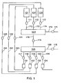
- Figure 1 sets forth a schematic diagram of one embodiment of the process of this invention.
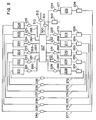
- FIG. 2 sets forth a schematic diagram of another embodiment of the process of this invention.
- This invention is particularly applicable to cleaning and anodizing metallic parts, and applying chemical conversion coatings to such parts.
- the parts to be chemically processed are placed in a process tank, which is capable of receiving at least one part.
- Each of the process solutions is stored in separate storage tanks.
- Each storage tank is in fluid communication with the process tank, which in turn is in fluid communication with one or more transition tanks.
- the process begins, the parts to be processed are placed in the process tank and the lid is closed.
- the first solution is then provided into the process tank. After the first solution has been in the tank for a predetermined time, the first solution is provided into the transition tank.
- a spray rinse system is activated and the parts and the process tank are rinsed to remove all remaining process solution. While this is occurring, the first solution in the transition tank is recycled back into its storage tank. Once the first solution has been recycled from the transition tank back to its storage tank, the rinse water from the process tank is provided into the transition tank.
- the second process solution is provided into the process system.
- the rinse water in the transition tank is provided into a waste removal tank, which is in fluid communication with the transition tank.
- the transition tank may also have a spray rinse system, which is employed while the tank is pumped out, to completely remove all traces of the process solution.
- the pump is turned off and the dump valves are closed, preparing the transition tank to receive the second process solution. This sequence is repeated for each storage tank.
- each storage tank is in fluid communication with the process tank, which in turn is in fluid communication with a plurality of transition tanks.
- the process sequences are the same, with the inclusion of provisions for running an electrical current through the parts in the process tank to perform the anodizing process, as will be understood by those skilled in the art.
- the parts are electrically grounded during the entire process sequence, but electrical current will only be applied during the appropriate step in the process.
- each storage tank 101, 102, and 103 are provided, each capable of containing a different solution.
- each storage tank will contain about 150 gallons of the respective solution, and will have a total capacity of 250 gallons per tank.
- Each storage tank 101, 102, and 103 has a number of lines, through which fluid communication is provided with the process tank 104 and the transition tank 105.
- the storage tanks 101, 102, and 103 are in one-way fluid communication with the process tank 104 via lines 170, 172, and 174, respectively, the process tank 104 is in one-way fluid communication with the transition tank 105 via line 176, and the transition tank 105 is in one-way fluid communication with the storage tanks 101, 102, and 103 via lines 190, 192, and 194 as shown.
- the transition tank 105 has a 250 gallon capacity, although only 150 gallons are planned for normal use.
- the process tank 104 is capable of receiving at least one part.
- the process tank 104 may have a 250 gallon capacity, of which 150 gallons are planned for normal use.
- lines 170, 172, and 174 are lines through which material is provided to the process tank 104 from the storage tanks 101, 102, and 103.
- Lines 190, 192, and 194 connected to each storage tank 101, 102, and 103, the fluid communication of which is controlled by valves 121, 122, and 123, respectively, are lines used to provide solution to the storage tanks 101, 102, and 103 from the transition tank 105.
- Other lines on the storage tank may provide fluid communication by any method known in the art.
- a pipe is attached to the storage tank.
- This pipe may have an air-venting valve attached to equalize the pressure in the tank when material is removed or provided to the tank.
- Another line (not shown) is a tube through which the wiring for the tank fluid sensor is run.
- the lid of the tank is bolted to the frame and has a neoprene rubber seal. The lid is designed to allow maintenance and cleaning of the tank as needed.
- a mechanical mixer capable of mixing the solutions in the process tank may be added to the side of the process tank, as will be well understood by those skilled in the art.
- the process tank 104 has a plurality of lines 170, 172 and 174 providing fluid communication from the storage tanks 101, 102, and 103, at line 176 provides fluid communication to the transition tank 105.
- Lines 170, 172, and 174, the fluid communication of which is controlled by valves 111, 112, and 113, respectively, are interconnected to the process tank 104. Through these lines, the process solutions are provided from the storage tanks 101, 102, and 103 into the process tank 104.
- line 176 the fluid communication of which is controlled by valve 115, the various process solutions contained in process tank 104 are provided to the transition tank 105.
- a pipe with an air vent valve welded to the lid may aid in pressure equalization of the process tank 104 during fluid fill and removal.
- a tube fitting is attached to the tank for the wiring for the process tank 104 fluid level sensor (not shown).
- the lines used in this invention are pipes, which may be fabricated from CPVC tubing or Type 316L stainless steel pipe.
- the tube or pipe may be connected to the process tank 104 through composite metal/plastic connectors. These connectors may be flanged and sealed to the process tank 104 to prevent leakage.
- Additional lines may be added to process tank 104, including a line through which a pH sensor may be placed.
- the rinse time using rinse water may be input into a control system, and the rinse cycle can be controlled through monitoring the pH of the rinse water.
- the lid (not shown) of process tank 104 may be attached to a welded machined lip on the tank, and neoprene rubber gaskets may be attached to the tank lip.
- a pneumatic pressure cylinder may be attached to the lid for opening and closing and will also apply pressure while the system is active to keep the lid of process tank 104 tightly closed.
- each of the solutions is provided into the process tank 104 from the storage tanks 101, 102, and 103 through lines 170, 172, and 174, respectively, which are controlled by valves 111, 112, and 113, respectively, as shown.
- One solution which may be an alkaline solution, is stored in storage tank 101.
- this solution may contain the solute GMC 528B available from Gus Mar Company.
- the solute GMC 528B has a concentration of about 30 to about 34 ounces per gallon and is used to process the part or parts for about 10 to about 15 minutes.
- this solution may be a chemical polish solution, such as GMC 800, available from Gus Mar Company. This solution may be kept at ambient temperature, and can be used to treat the part in process tank 104.
- the solute GMC 800 has a concentration of about 18 to about 22% by volume. The solute is maintained at a temperature of about 165 to about 175°F, and is used to treat the part or parts for about 10 to about 15 minutes.
- a second solution which may be a deoxidizing acid solution, is stored in storage tank 102.
- this solution may be a deoxidizer or etchant containing, for example, the solvent AMCHEM 7-17, available from Amchem Corporation, and nitric acid.
- the AMCHEM 7-17 is maintained at a concentration of about 2.3 to about 5.4 ounces per gallon.
- the nitric acid is maintained at a concentration of about 7.5 to about 15 % by volume.
- the solutions are maintained at ambient temperature, and are used to treat the part or parts for about 10 to about 20 minutes in process tank 104.
- this solution used to treat the part or parts may be an anodizing solution.
- the anodizing solution contains about 8% sulfuric acid as the solute.
- the anodizing solution is maintained at ambient temperature, and is used to treat the part or parts for about 30 minutes.
- a third solution which may be a coating solution having a pH of about 1.0 to about 3.0, is stored in storage tank 103.
- this solution may contain the solutions ALODINE 1200, available from Parker-Amchem and Henkel Corporations, and nitric acid.
- the coating provided by this solution allows paint to adhere to the coated part and prevents salt water corrosion.
- the ALODINE 1200 is maintained at a concentration of about 1.3 to about 1.8 ounces per gallon.
- the nitric acid is maintained at a concentration necessary to control pH to about 1.5 to about 3.0. Both solutions are maintained at ambient temperature, and are used to treat the part in tank 104 for about 2 to about 5 minutes.
- this solution may be a dichromate sealing solution, which may be sodium dichromate, available from any commercial suppliers.
- sodium dichromate is maintained at a concentration of about 5.4 to about 8.0 ounces per gallon.
- the dichromate seal solution is maintained at a temperature of about 208 to about 212 degrees Fahrenheit, and is used to treat the part or parts in process tank 104 for about 15 minutes.
- any solution may be kept in any of storage tanks 101, 102, and 103.
- the first, second, and third storage tanks 101, 102, and 103 are in fluid communication with process tank 104, as shown.
- the solutions are provided to process tank 104 from storage tanks 101, 102, and 103 via lines 170, 172 and 174, respectively.
- process tank 104 is evacuated and the solution is provided into transition tank 105.
- the transition tank 105 is in fluid communication with the first, second, and third storage tanks, as shown, such that each solution residing in transition tank 105 may be removed into storage tanks 101, 102, and 103 via respective lines 190, 192, and 194, as shown.
- a system of rinse nozzles may be activated and the parts will be spray rinsed in process tank 104 for a predetermined time.
- the rinse water may be provided and controlled via valve 114 through line 178.
- the original solution in the transition tank 105 has been provided into its respective storage tank 101, 102, or 103.
- the rinse water is then provided into the transition tank 105, and the next process solution is provided from the next storage tank, such as tank 102, to the process tank 104. This cycle, with a rinse between each process cycle, will continue until the total process sequence is complete.
- the process tank 104 is fabricated from Type 316L stainless steel.
- the process tank 104 has a plurality of lines. Through line 176, controlled by valve 115, the process solutions will be provided from the process tank 104 into the transition tank 105. Additional lines (not shown) from process tank 104 may be directed to a waste removal tank (not shown), which is in fluid communication with the process tank 104. A pump (not shown) may be used to pump this waste out of the process tank 104. Lines 190, 192, and 194, the fluid communication of which is controlled by valves 117, 118, and 119, respectively, as well as valves 121, 122, and 123, respectively, provide fluid communication between transition tank 105 and storage tanks 101, 102, and 103.
- valves 117, 118, and 119 are connected to pneumatic actuated pumps, numbered as pumps 131, 132, and 133, respectively.
- the material is then provided into the storage tanks 101, 102, and 103 through lines 190, 192, and 194, respectively, which are controlled by valves 121, 122, and 123, respectively.
- Line 196, controlled by valve 120, may be directed to a waste removal tank (not shown), which is in fluid communication with the transition tank 105.
- Pump 134 may be used to pump this waste out of the transition tank 105.
- the waste removal tank is mobile and can be removed when full.
- a pipe (not shown) may be welded to the lid of the waste removal tank, and contains a vent valve (not shown) for pressure relief during fluid fill and removal.
- the transition tank 105 is in fluid connection with a line 188 through which the pipe for the rinse system is fed. Fluid flow (e.g. water flow) through the rinse system is controlled by valve 116.
- the rinse system may contain pipes, and the pipes will be fabricated from CPVC tubing or Type 316L stainless steel.
- first, second, and third transition tanks may exist in fluid communication with the process tank 104 and the first, second, and third storage tanks 101, 102, and 103, respectively.
- the process system will be controlled by a programmable control system such as an Allen Bradley programmable control system.
- the control system may, for example, drive a bank of air solenoids, one for each valve and pump. Fluid level control may be added to the storage tanks, pH may be monitored during the rinse cycles, and the heating and electrical sub-systems may be automatically controlled for the sulfuric acid anodizing system.
- a process solution concentration monitoring system and a Total Productive Maintenance (TPM) program for maintaining the process system can be incorporated into the process system.
- TPM Total Productive Maintenance
- the control system may be programmed so that the system will not be activatable until such time as the regular preventive maintenance has been completed on a weekly or daily basis, as necessary.
- a moisture sensor may be located in a fluid catch pan located in the bottom of the frame.
- the fluid catch pan has enough capacity to hold about 300 gallons.
- the sensor may have an audible alarm to make operators aware of a material leak from the system.
- the sensor may be incorporated into the control system so that when the sensor detects moisture, the system will automatically shut down.
- the lid of the process tank 104 may be opened and closed with a pneumatic cylinder.
- the lid activation sequence may exist as one element of the control system, and the operator will not be able to activate the lid opening sequence until the process cycle is complete. This embodiment helps in preventing exposure of the operator to the solutions used in either system.
- all of the storage tank return lines 190, 192, and 194 may include manual two way gate valves.
- the solutions may be provided into a waste removal tank using the in-line pumps 131, 132 and 133.
- the valves will also allow for sampling of the process solutions by laboratory personnel.
- all plumbing with the exception of the piping supporting the rinse systems inside process tank 104 and transition tank 105, will be made of Type 316L stainless steel.
- All valves may also be made from Type 316L stainless steel, and are air actuated ball valves with a TEFLON coated ball.
- All pumps may be air actuated.
- all air lines to the pumps and the valves will be made of Type 304 stainless steel tubing. All of the pumps and valves may be controlled by air solenoids located on one side of the frame directly adjacent to the control system and display.
- the process system elements may be contained within and are attached to a frame of Type 304L stainless steel rectangular tubing.
- the frame will support all of the tanks and ancillary elements.
- the frame may include provisions for bolting the entire system to the floor.
- a stainless steel catch pan may be placed inside the frame, located at floor level, to prevent spills in the event of catastrophic failure of any storage tanks or in the plumbing.
- sheet metal covers are attached to the outside of the frame, concealing all elements of the system except the process tank and the screen for the automated control system.
- Table I summarizes the various solutions which may be employed in the embodiment of this invention depicted in Figure 1, their concentrations, their temperatures, and the times that each solution will typically be used to treat the parts: SOLUTION TYPE SOLUTE CONCENTRATION TEMPERATURE PROCESS TIME 1-1 Alkaline Cleaner GMC 528B 30-34 oz/gal Ambient 10-15 min 1-2 Deoxidizer AMCHEM 7-17; Nitric Acid 2.3-5.4 oz/gal Ambient 10-20 min 7.5-15% by volume 1-3 Coating ALODINE 1200; Nitric Acid 1.2-1.5 oz/gal Ambient 2-5 min As needed to control pH to 1.5-2.0
- FIG. 2 Another embodiment of this invention is shown in Figure 2.
- This embodiment which includes a process and an apparatus, employs individual storage tanks, numbered as 201, 202, 203, 204, 205, and 206, respectively, which will contain different chemical solutions.
- the tanks may be fabricated from welded Type 316L stainless steel.
- each storage tank 201, 202, 203, 204, 205, and 206 has a number of lines for fluid communication, through which fluid communication is provided with process tank 207 and the transition tanks 208, 209, 210, 211, 212, and 213.
- the storage tanks 201, 202, 203, 204, 205, and 206 are in one-way fluid communication with process tank 207 via lines 260, 261, 262, 263, 264, and 265, respectively, process tank 207 is in one way fluid communication with the transition tanks 208, 209, 210, 211, 212, and 213 via lines 266, 267, 268, 269, 270, and 271, respectively, and transition tanks 208, 209, 210, 211, 212, and 213 are in one-way fluid communication with storage tanks 201, 202, 203, 204, 205, and 206 via lines 272, 273, 274, 275, 276, and 277. Furthermore, process tank 207 is capable of receiving at least one part.
- the process tank 207 has about a 250 gallon capacity, of which about 150 gallons are planned for normal use.
- each of the storage tanks 201, 202, 203, 204, 205, and 206 will contain about 150 gallons of the respective solutions, and will have a total capacity of about 200 gallons per tank.
- each transition tank 208, 209, 210, 211, 212, and 213 will have a capacity of about 200 gallons.
- storage tanks 201, 202, 203, 204, 205, and 206 the fluid communication of which is controlled by valves 221, 222, 223, 224, 225, and 226 through lines 260, 261, 262, 263, 264, and 265, respectively, are in fluid communication with process tank 207.
- Lines 272, 273, 274, 275, 276 and 277 the fluid communication of which is controlled by valves 235, 236, 237, 238, 239 and 240, respectively, provide fluid communication between the storage tanks 201, 202, 203, 204, 205 and 206 and the transition tanks 208, 209, 210, 211, 212, and 213, respectively.
- a pipe is attached. This pipe may have an air-venting valve attached to equalize the pressure in process tank 207 when material is removed or provided to process tank 207.
- Another line (not shown) is a tube through which the wiring for the process tank 207 fluid level sensor is run.
- the lid of process tank 207 is bolted to the frame and has a neoprene rubber seal, to allow maintenance and cleaning of process tank 207 as needed.
- any or all of storage tanks 201-206 are capable of receiving heated solutions.
- the storage tank when a storage tank contains heated solutions, the storage tank also contains at least two additional lines (not shown). Immersion heaters are fed through a first additional line. A control and monitoring thermocouple is fed through a second additional line. Both of the inputs for the heating system will be located on the storage tank.
- the last two lines are for a pipe which has a fan-cooled heat exchanger and condenser attached to condense evaporated liquids and return them to the storage tank.
- the storage tank will only vent any water vapor during the return cycle, when the solution is provided to the storage tank. At all other times, the system will operate as a closed loop recycling system.
- a mechanical mixer capable of mixing the solution, and the required line for the mixer, can be added to one or more of storage tanks 201-206.
- those of storage tanks 201-206 that contain heated solutions or rinses will be wrapped with a blanket type insulation to help maintain the temperature of these solutions and to minimize energy usage.
- the system contains a process tank 207.
- process tank 207 is fabricated from welded Type 316L stainless steel.
- Process tank 207 is connected to storage tanks 201 - 206 via a plurality of lines 260-265 as shown. Through these lines, controlled by valves 221 - 226, respectively, the process solutions are provided from storage tanks 201-206 into process tank 207. After treating the part, each of the process solutions is provided from the process tank 207 to the transition tanks 208-213, respectively, via lines 266-271, as shown.
- a pipe (not shown) may be welded to the lid of process tank 207 for air venting during fluid fill and removal.
- a tube fitting is attached to the tank for the wiring for the tank fluid fill sensor.
- the pipes for the rinse system are fed through two lines (not shown) in process tank 207.
- a waste line 300 containing valve 301 and pump 302 is also provided to remove waste rinse water from process tank 207.
- An optional waste transition tank (not shown) may be used to receive the waste rinse water from line 300.
- the waste transition tank may be mobile and may be removed when full.
- the rinse system pipes will be fabricated from CPVC tubing or Type 316L stainless steel pipe.
- the tubing or pipe may be connected to process tank 207 with composite metal or plastic connectors, which will be flanged and sealed to process tank 207 to prevent leakage.
- a line (not shown) may be added to process tank 207, through which a pH sensor may be fed.
- the rinse time may be input into the control system, and the rinse cycle may be controlled through monitoring of the pH of the rinse water.
- process tank 207 will be wrapped with a blanket type insulation to help retain heat during those periods when heated solutions are in the tank.
- Immersion-type heaters may be added to process tank 207.
- each of the parts to be processed will be clipped to the frame of the basket with a wire clip, and another clip completing an electric circuit will attach to a connector on the inside of the tank.
- process tank 207 from storage tanks 201-206 using appropriate pipes and valves.
- process tank 207 will be evacuated and the solution will be provided into one or more transition tanks such as transition tanks 208-213.
- a system of rinse nozzles (not shown) will be activated and the process tank 207 and the parts contained therein will be spray rinsed for a predetermined time.
- Rinse water is provided to process tank 207 via line 310 controlled by valve 312.
- the rinse water is then provided into waste tank 302 via line 300, the fluid communication of which is controlled by valve 301, and the next process solution is provided into process tank 207.
- This cycle with a rinse between each process solution, will continue until the total process sequence is complete.
- the process may include an anodizing phase, during which an electrical current will be introduced into the process tank 207.
- the system may contain a total of up to six transition tanks 208-213.
- the tanks are fabricated from welded Type 316L stainless steel.
- Each transition tank has a plurality of lines. Through a line, the process solutions will be provided from the process tank. Lines may also be attached to each transition tank. Each line may have a valve, preferable a ball valve attached. Optionally, each ball valve is attached to a pneumatic pump. As each process solution is provided into its respective transition tank, the material is then provided back into the storage tanks through lines 272-277, optionally via pumps 251-256.
- a line (not shown) may be welded to the lid for air venting during fluid fill and removal. The line for the rinse system will be fed into the process tank 207.
- the rinse system pipes will be fabricated from CPVC tubing or Type 316L stainless steel.
- storage tank 201 will contain a first solution, which may be an alkaline cleaner solution.
- this solution may contain solution GMC 528B, available from Gus Mar Company. This solution may be kept at ambient temperature, and can be used to treat the part or parts in process tank 207.
- the GMC 528B has a concentration of about 30 to about 34 ounces per gallon, and is used to treat the part in process tank 207 for about 10 to about 15 minutes.
- Storage tank 202 will contain a second solution, which may be a chemical polishing solution.
- Storage tank 202 the second storage tank, is capable of receiving such a chemical polishing solution.
- the chemical polishing solution may contain solution GMC 800, available from Gus Mar Company. GMC 800 is maintained at a concentration of about 18 to about 22% by volume, at a temperature of about 165 to about 175°F, and is used to treat the part or parts in process tank 207 for about 7 to about 10 minutes.
- Storage tank 203 will contain a third solution, which may be a deoxidizer solution such as an acid solution.
- the third solution may contain two solutions, AMCHEM 7-17, available from Amchem Corporation, and nitric acid.
- AMCHEM 7-17 is a combination of the following components: AMCHEM 7 and AMCHEM 17.
- AMCHEM 7-17 is maintained at a concentration of about 2.3 to about 5.4 ounces per gallon.
- Nitric acid is maintained at a concentration of about 7.5 to about 15 % by volume. Both solutions are maintained at ambient temperature, and are used to treat the part or parts in process tank 207 for about 10 to about 20 minutes.
- Storage tank 204 will contain a fourth solution, which may be an anodizing solution, such as sulfuric acid available from commercial sources.
- sulfuric acid is the solute in the fourth solution.
- sulfuric acid is maintained at a concentration of about 8% to about 9% by volume.
- the fourth solution may be kept at ambient temperature, and is used to treat the part or parts in process tank 207 for about 30 minutes.
- Storage tank 205 will contain a fifth solution, which may be a dichromate sealing solution containing sodium dichromate.
- Storage tank 205 the fifth storage tank, is capable of receiving such a dichromate sealing solution.
- sodium dichromate is the solute in the fifth solution.
- sodium dichromate is maintained at a concentration of about 5.4 to about 8.0 ounces per gallon.
- the solution is maintained at a temperature of about 208 - 212°F, and is used to treat the part or parts in process tank 207 for about 15 minutes.
- Storage tank 206 will contain a sixth solution, which may be a chemical conversion coating solution having a pH of about 1.0 to about 3.0.
- Storage tank 206, the sixth storage tank is capable of receiving a sixth solution, which may be a coating solution having a pH of about 1.0 to about 3.0.
- the coating solution is "Type II" coating, i.e., a coating which allows paint to adhere and reduces salt water corrosion, in which the solutes are ALODINE 1200 and nitric acid.
- ALODINE 1200 is maintained at a concentration of about 1.3 to about 1.8 ounces per gallon, while nitric acid is maintained at a concentration necessary to control pH from about 1.0 to about 3.0.
- the coating solution is maintained at ambient temperature, and is used to treat the part or parts for about 2 to about 5 minutes. The skilled artisan will recognize that any solution may be kept in any of storage tanks 201-206.
- only the solutions in tanks 201, 203, and 206 are used to treat the part or parts in process tank 207.
- only the solutions in tanks 201, 203, 204, and 205 are used to treat the part or parts in process tank 207.
- the solutions in tanks 201 and 202 may be used to pretreat the parts prior to treatment as described herein.
- Table II summarizes the various solutions which may be employed in the embodiment of this invention depicted in Figure 2, their concentrations, their temperatures, and the times that each solution will be used to process the parts: SOLUTION TYPE SOLUTE CONCENTRATION TEMPERATURE PROCESS TIME 2-1 Alkaline Cleaner GMC 528B 30-34 oz/gal Ambient 10-15 min 2-2 Chemical Polish GMC 800 18-22% by volume 165-175°F 7-10 min 2-3 Deoxidizer AMCHEM 7-17; Nitric Acid 2.3-5.4 oz/gal Ambient 10-20 min 7.5-15% by volume 2-4 Anodizing Solution Sulfuric Acid 8% by volume Ambient 30 min 2-5 Dichromate Seal Sodium Dichromate 5.4-8.0 oz/gal 208-212°F 15 min 2-6 Coating ALODINE 1200; Nitric Acid 1.2-1.5 oz/gal Ambient 2-5 min As needed to control pH to 1.5-2.0
- solutions 2-1 and 2-2 are contacted with the part or parts to effect stripping prior to further treatment of the part.
- acidic treatment and anodizing of the part or parts are achieved by employing only solutions 2-1, 2-3, 2-4, and 2-5 as described herein.
Landscapes
- Chemical & Material Sciences (AREA)
- Engineering & Computer Science (AREA)
- Chemical Kinetics & Catalysis (AREA)
- Electrochemistry (AREA)
- Materials Engineering (AREA)
- Metallurgy (AREA)
- Organic Chemistry (AREA)
- Automation & Control Theory (AREA)
- ing And Chemical Polishing (AREA)
- Coating Apparatus (AREA)
- Chemical Treatment Of Metals (AREA)
Applications Claiming Priority (2)
| Application Number | Priority Date | Filing Date | Title |
|---|---|---|---|
| US973574 | 2001-10-05 | ||
| US09/973,574 US20030122292A1 (en) | 2001-10-09 | 2001-10-09 | Chemical processing system |
Publications (2)
| Publication Number | Publication Date |
|---|---|
| EP1302568A2 true EP1302568A2 (fr) | 2003-04-16 |
| EP1302568A3 EP1302568A3 (fr) | 2006-09-06 |
Family
ID=25521033
Family Applications (1)
| Application Number | Title | Priority Date | Filing Date |
|---|---|---|---|
| EP02021266A Withdrawn EP1302568A3 (fr) | 2001-10-09 | 2002-09-19 | Système et procédé de traitement chimique |
Country Status (2)
| Country | Link |
|---|---|
| US (1) | US20030122292A1 (fr) |
| EP (1) | EP1302568A3 (fr) |
Cited By (1)
| Publication number | Priority date | Publication date | Assignee | Title |
|---|---|---|---|---|
| US20210395912A1 (en) * | 2015-11-05 | 2021-12-23 | Topocrom Systems Ag | Method and device for the galvanic application of a surface coating |
Families Citing this family (2)
| Publication number | Priority date | Publication date | Assignee | Title |
|---|---|---|---|---|
| FR2958301B1 (fr) * | 2010-03-31 | 2015-02-13 | Snecma | Procede et installation pour traiter la surface de pieces, par voie liquide. |
| JP7175187B2 (ja) * | 2018-12-28 | 2022-11-18 | 株式会社荏原製作所 | めっき方法 |
Family Cites Families (9)
| Publication number | Priority date | Publication date | Assignee | Title |
|---|---|---|---|---|
| US2636257A (en) * | 1950-09-23 | 1953-04-28 | Westinghouse Electric Corp | Protective finish for metals |
| US3053691A (en) * | 1958-01-29 | 1962-09-11 | Allied Res Products Inc | Protective coating |
| US4310390A (en) * | 1977-08-10 | 1982-01-12 | Lockheed Corporation | Protective coating process for aluminum and aluminum alloys |
| US4346128A (en) * | 1980-03-31 | 1982-08-24 | The Boeing Company | Tank process for plating aluminum substrates including porous aluminum castings |
| US4504325A (en) * | 1982-03-19 | 1985-03-12 | The Boeing Company | Method for sealing an aluminum oxide film |
| JPH03505348A (ja) * | 1988-11-24 | 1991-11-21 | グラム,ゲルハルト | ワークピースにおいて被覆部を積層および/または除去する装置 |
| US5486283A (en) * | 1993-08-02 | 1996-01-23 | Rohr, Inc. | Method for anodizing aluminum and product produced |
| US5750014A (en) * | 1995-02-09 | 1998-05-12 | International Hardcoat, Inc. | Apparatus for selectively coating metal parts |
| KR100605537B1 (ko) * | 1998-08-28 | 2006-07-28 | 알코아 인코포레이티드 | 알루미늄 제품의 표면 처리 방법 |
-
2001
- 2001-10-09 US US09/973,574 patent/US20030122292A1/en not_active Abandoned
-
2002
- 2002-09-19 EP EP02021266A patent/EP1302568A3/fr not_active Withdrawn
Cited By (2)
| Publication number | Priority date | Publication date | Assignee | Title |
|---|---|---|---|---|
| US20210395912A1 (en) * | 2015-11-05 | 2021-12-23 | Topocrom Systems Ag | Method and device for the galvanic application of a surface coating |
| US11732373B2 (en) * | 2015-11-05 | 2023-08-22 | Topocrom Systems Ag | Method and device for the galvanic application of a surface coating |
Also Published As
| Publication number | Publication date |
|---|---|
| EP1302568A3 (fr) | 2006-09-06 |
| US20030122292A1 (en) | 2003-07-03 |
Similar Documents
| Publication | Publication Date | Title |
|---|---|---|
| EP0304084A2 (fr) | Rinçage-filtrage d'agent de refroidissement pour machine employant la pression du gaz extérieur | |
| US5750014A (en) | Apparatus for selectively coating metal parts | |
| JP2010504855A (ja) | 水処理システム | |
| JPH02233194A (ja) | 超純水ラインの滅菌方法 | |
| RU2001106433A (ru) | Способ очистки теплоэнергетического оборудования от отложений и накипи и устройство для его осуществления | |
| US4809769A (en) | Engine coolant flush-filtering using external gas pressure | |
| US20030122292A1 (en) | Chemical processing system | |
| JP2002538610A (ja) | 半導体ウェーハ処理 | |
| JP2739419B2 (ja) | 基板処理装置 | |
| US5534126A (en) | Apparatus and method for selective coating of metal parts | |
| US6016820A (en) | Aqueous cleaning system | |
| US6149731A (en) | Valve cleaning method | |
| CA2560337C (fr) | Procede et appareil pour deposer une couche electrogalvanique sur des articles en metal | |
| US20180195191A1 (en) | System and method for local surface treatment | |
| US7938909B2 (en) | Automated sanitation | |
| US12371348B2 (en) | Systems and methods for cleaning water filtration systems | |
| JP2671068B2 (ja) | 放射性汚染物の除染により生じる放射性汚染水の減量装置 | |
| KR100791758B1 (ko) | 중장비용 탱크 제조방법 | |
| CN213763049U (zh) | 清洁设备、分配装置以及处理设备 | |
| JP3263222B2 (ja) | 電着塗料供給装置 | |
| US9947425B2 (en) | Method for reducing the radioactive contamination of the surface of a component used in a nuclear reactor | |
| NO175906B (no) | Fremgangsmåte for metallbelegging av innvendige flater i tanker og rör | |
| JP2009106902A (ja) | 洗浄システム | |
| JP3810923B2 (ja) | 化学除染法における系統隔離方法 | |
| JPS58161797A (ja) | 電着塗装装置における熱利用システム |
Legal Events
| Date | Code | Title | Description |
|---|---|---|---|
| PUAI | Public reference made under article 153(3) epc to a published international application that has entered the european phase |
Free format text: ORIGINAL CODE: 0009012 |
|
| AK | Designated contracting states |
Designated state(s): AT BE BG CH CY CZ DE DK EE ES FI FR GB GR IE IT LI LU MC NL PT SE SK TR |
|
| AX | Request for extension of the european patent |
Extension state: AL LT LV MK RO SI |
|
| PUAL | Search report despatched |
Free format text: ORIGINAL CODE: 0009013 |
|
| STAA | Information on the status of an ep patent application or granted ep patent |
Free format text: STATUS: THE APPLICATION IS DEEMED TO BE WITHDRAWN |
|
| AK | Designated contracting states |
Kind code of ref document: A3 Designated state(s): AT BE BG CH CY CZ DE DK EE ES FI FR GB GR IE IT LI LU MC NL PT SE SK TR |
|
| AX | Request for extension of the european patent |
Extension state: AL LT LV MK RO SI |
|
| 18D | Application deemed to be withdrawn |
Effective date: 20060401 |