EP1302630A2 - Dispositif pour déphaser les soupapes d'échange de gaz d'un moteur à combustion interne, notamment déphaseur à piston rotatif pour déphaser un arbre à cames relativement au vilebrequin - Google Patents
Dispositif pour déphaser les soupapes d'échange de gaz d'un moteur à combustion interne, notamment déphaseur à piston rotatif pour déphaser un arbre à cames relativement au vilebrequin Download PDFInfo
- Publication number
- EP1302630A2 EP1302630A2 EP02020920A EP02020920A EP1302630A2 EP 1302630 A2 EP1302630 A2 EP 1302630A2 EP 02020920 A EP02020920 A EP 02020920A EP 02020920 A EP02020920 A EP 02020920A EP 1302630 A2 EP1302630 A2 EP 1302630A2
- Authority
- EP
- European Patent Office
- Prior art keywords
- locking element
- impeller
- drive wheel
- receptacle
- internal combustion
- Prior art date
- Legal status (The legal status is an assumption and is not a legal conclusion. Google has not performed a legal analysis and makes no representation as to the accuracy of the status listed.)
- Granted
Links
- 238000002485 combustion reaction Methods 0.000 title claims description 28
- 230000006835 compression Effects 0.000 claims description 5
- 238000007906 compression Methods 0.000 claims description 5
- 230000007704 transition Effects 0.000 claims description 4
- 230000002093 peripheral effect Effects 0.000 claims description 3
- 230000008878 coupling Effects 0.000 abstract 1
- 238000010168 coupling process Methods 0.000 abstract 1
- 238000005859 coupling reaction Methods 0.000 abstract 1
- 238000004519 manufacturing process Methods 0.000 description 6
- 239000000853 adhesive Substances 0.000 description 3
- 230000001070 adhesive effect Effects 0.000 description 3
- 238000013461 design Methods 0.000 description 3
- 238000009423 ventilation Methods 0.000 description 3
- 238000011161 development Methods 0.000 description 2
- 239000002245 particle Substances 0.000 description 2
- 239000000725 suspension Substances 0.000 description 2
- 230000002411 adverse Effects 0.000 description 1
- 230000015572 biosynthetic process Effects 0.000 description 1
- 238000010276 construction Methods 0.000 description 1
- 230000000694 effects Effects 0.000 description 1
- 238000005516 engineering process Methods 0.000 description 1
- 230000007257 malfunction Effects 0.000 description 1
- 238000000034 method Methods 0.000 description 1
- 230000036316 preload Effects 0.000 description 1
- 238000007789 sealing Methods 0.000 description 1
- 230000035945 sensitivity Effects 0.000 description 1
- 239000007787 solid Substances 0.000 description 1
- 238000012546 transfer Methods 0.000 description 1
- 238000013022 venting Methods 0.000 description 1
Images

Classifications
-
- F—MECHANICAL ENGINEERING; LIGHTING; HEATING; WEAPONS; BLASTING
- F01—MACHINES OR ENGINES IN GENERAL; ENGINE PLANTS IN GENERAL; STEAM ENGINES
- F01L—CYCLICALLY OPERATING VALVES FOR MACHINES OR ENGINES
- F01L1/00—Valve-gear or valve arrangements, e.g. lift-valve gear
- F01L1/34—Valve-gear or valve arrangements, e.g. lift-valve gear characterised by the provision of means for changing the timing of the valves without changing the duration of opening and without affecting the magnitude of the valve lift
- F01L1/344—Valve-gear or valve arrangements, e.g. lift-valve gear characterised by the provision of means for changing the timing of the valves without changing the duration of opening and without affecting the magnitude of the valve lift changing the angular relationship between crankshaft and camshaft, e.g. using helicoidal gear
- F01L1/3442—Valve-gear or valve arrangements, e.g. lift-valve gear characterised by the provision of means for changing the timing of the valves without changing the duration of opening and without affecting the magnitude of the valve lift changing the angular relationship between crankshaft and camshaft, e.g. using helicoidal gear using hydraulic chambers with variable volume to transmit the rotating force
-
- F—MECHANICAL ENGINEERING; LIGHTING; HEATING; WEAPONS; BLASTING
- F01—MACHINES OR ENGINES IN GENERAL; ENGINE PLANTS IN GENERAL; STEAM ENGINES
- F01L—CYCLICALLY OPERATING VALVES FOR MACHINES OR ENGINES
- F01L1/00—Valve-gear or valve arrangements, e.g. lift-valve gear
- F01L1/34—Valve-gear or valve arrangements, e.g. lift-valve gear characterised by the provision of means for changing the timing of the valves without changing the duration of opening and without affecting the magnitude of the valve lift
- F01L1/344—Valve-gear or valve arrangements, e.g. lift-valve gear characterised by the provision of means for changing the timing of the valves without changing the duration of opening and without affecting the magnitude of the valve lift changing the angular relationship between crankshaft and camshaft, e.g. using helicoidal gear
- F01L1/3442—Valve-gear or valve arrangements, e.g. lift-valve gear characterised by the provision of means for changing the timing of the valves without changing the duration of opening and without affecting the magnitude of the valve lift changing the angular relationship between crankshaft and camshaft, e.g. using helicoidal gear using hydraulic chambers with variable volume to transmit the rotating force
- F01L2001/34423—Details relating to the hydraulic feeding circuit
- F01L2001/34436—Features or method for avoiding malfunction due to foreign matters in oil
-
- F—MECHANICAL ENGINEERING; LIGHTING; HEATING; WEAPONS; BLASTING
- F01—MACHINES OR ENGINES IN GENERAL; ENGINE PLANTS IN GENERAL; STEAM ENGINES
- F01L—CYCLICALLY OPERATING VALVES FOR MACHINES OR ENGINES
- F01L1/00—Valve-gear or valve arrangements, e.g. lift-valve gear
- F01L1/34—Valve-gear or valve arrangements, e.g. lift-valve gear characterised by the provision of means for changing the timing of the valves without changing the duration of opening and without affecting the magnitude of the valve lift
- F01L1/344—Valve-gear or valve arrangements, e.g. lift-valve gear characterised by the provision of means for changing the timing of the valves without changing the duration of opening and without affecting the magnitude of the valve lift changing the angular relationship between crankshaft and camshaft, e.g. using helicoidal gear
- F01L1/3442—Valve-gear or valve arrangements, e.g. lift-valve gear characterised by the provision of means for changing the timing of the valves without changing the duration of opening and without affecting the magnitude of the valve lift changing the angular relationship between crankshaft and camshaft, e.g. using helicoidal gear using hydraulic chambers with variable volume to transmit the rotating force
- F01L2001/3445—Details relating to the hydraulic means for changing the angular relationship
- F01L2001/34453—Locking means between driving and driven members
- F01L2001/34469—Lock movement parallel to camshaft axis
Definitions
- the invention relates to a device for changing the control times of gas exchange valves an internal combustion engine according to the generic features of claim 1, and it is particularly advantageous on rotary piston adjusting device for adjusting the angle of rotation of a camshaft relative to a Realizable crankshaft.
- From DE 196 23 818 A1 is a generic valve timing control device known, the one at the drive end in the cylinder head Internal combustion engine mounted camshaft and in principle as in Dependency of various operating parameters of the internal combustion engine controllable hydraulic actuator is designed.
- This device consists in Essentially from a drive connection with a crankshaft of the internal combustion engine stationary drive wheel and from a rotationally fixed with a camshaft the internal combustion engine connected impeller, which with each other are in drive connection and the torque of the crankshaft on the Transfer camshaft of the internal combustion engine.
- the drive wheel has a hollow cylindrical peripheral wall and two side walls formed cavity in which by two radial boundary walls extending to the longitudinal central axis of the device two hydraulic work rooms are formed.
- the impeller points accordingly, on the circumference of his wheel hub two radially into the work spaces Extending wings, each of the working spaces in an A pressure chamber and subdivide a B-pressure chamber, which is optional or simultaneous pressurization with a hydraulic pressure medium Swiveling movement or fixing of the impeller in relation to the drive wheel and thus cause the camshaft relative to the crankshaft.
- the impeller is below one required for adjustment Pressure medium pressure, such as when switching off the internal combustion engine, by a separate locking element in a preferred Basic position within its adjustment range with the drive wheel mechanically can be coupled, in particular when restarting the internal combustion engine to build up the required pressure from the alternating torques resulting rattling of the impeller on the camshaft to avoid the boundary walls of the drive wheel.
- This, specifically as stepped cylindrical locking pin formed locking element is in a bore parallel to the longitudinal center axis of the device End of a wing of the impeller arranged and in by a spring element a locking position within a receptacle facing away from the camshaft Side wall of the drive wheel slidable.
- The is with a larger diameter portion of the locking pin due to the inner wall of the hole in the wing and the one with a smaller one Diameter formed section of the locking pin, the locking side for exact position determination between impeller and drive wheel is additionally conical, through a guide bush inserted into the bore guided.
- the inclusion of the locking pin is specific as in the side wall of the drive wheel facing away from the camshaft elongated bore formed in a direction transverse to the direction of rotation of the impeller and a groove with an A-pressure chamber of the device connected is. In addition, it is at the transition between the cylindrical ones Sections of the locking pin resulting from an annular surface Radial bore also connected to a B pressure chamber of the device, see above that both when pressurizing the A pressure chambers of the device as well as when pressurizing the B pressure chambers of the device Hydraulic locking pin in a decoupling position within the hole can be moved in the wing of the impeller.
- a disadvantage of this known device is that the arrangement of the locking pin in a hole at the end of a wing of the impeller a massive construction of the wing and therefore the number of possible hydraulic work spaces in the device to a maximum of three to four limited if the device has a normal adjustment angle of approx. 30 ° NW should be feasible.
- the conical version on the locking side of the locking pin with a constant taper angle above it also in connection with its elongated receiving hole in the remote from the camshaft Side wall of the drive wheel has the disadvantage that at locking high component loads on the impeller and the drive wheel of the device and that there is a risk of unlocking that it's for jamming the locking pin in the location hole comes.
- there is the increased space requirement and the relatively high manufacturing effort to be mentioned as a disadvantage for the graduated locking pin since this is the cause of a limited applicability of the device in confined spaces in the engine compartment and for relatively high manufacturing costs of the device.
- the invention is therefore based on the object of a device for changing the control times of gas exchange valves of an internal combustion engine, in particular rotary piston adjustment device for adjusting the angle of rotation to design a camshaft versus a crankshaft, which between their impeller and their drive wheel a simple and inexpensive has a lock that can be produced with a small space requirement, which largely unaffected by centrifugal forces and insensitive to dirt and which is arranged or designed so that the locked connection has high rigidity between the impeller and drive wheel and that universal use of the device also on SOHC motors or on Exhaust camshafts is possible.
- this object is achieved in a device according to the preamble of claim 1 solved such that the locking element as its entire length is formed evenly cylindrical locking pin and is arranged in an axial bore in the wheel hub of the impeller, whose longitudinal axis is the smallest possible distance from the longitudinal central axis of the Has device.
- the device designed according to the invention has the arranged in one of the side walls of the drive wheel Inclusion of the locking pin around a square and in its area a defined all-round play larger than the cross-sectional area of the locking pin trained contour and is with a confluent Worm groove designed for pressure medium supply with one in the locked position of the impeller unpressurized
- a pressure chamber of the device connected is and thus causes that the inclusion of the locking pin only at Pressurizing the pressure chambers of the device with the for unlocking the locking pin necessary pressure of the hydraulic pressure medium is acted upon.
- the locking pin on its towards the recording end with a phase and a rounding of its end edge and is formed with a hollow end face, while he has a basic hole in his rear face for fixing one End of the spring element, which is preferably designed as a compression coil spring having.
- the other end of the spring element is supported on one in the axial hole used for the locking pin and with a centering tip trained counterholder, which preferably has a Y-shaped profile cross section and in which the formed between its profile legs Longitudinal grooves are also provided for the pressure medium ventilation of the axial bore are.
- the formation of the receiving end of the locking pin with the The defined contour described here serves to ensure that the during of the unlocking process starting from a certain point Torque loading of the locking pin does not jam the same causes or a safe and accelerated unlocking of the locking pin allows.
- the A pressure chambers of the device and those connected to it Receiving the locking pin corresponding point has the locking pin one that has not yet been completely moved into its unlocked position Position in which by the constantly increasing pressure of the hydraulic Pressure means a relative rotation between the impeller due to play and uses the drive wheel of the device and thereby on the Circumferential surface of the locking pin occurring contour edge of its recording exerts a shear force or a torque on the locking pin.
- the hollow design of the receiving end face of the locking pin has been used to reduce the adhesive forces between the surface this end face and the stop surface in the receptacle of the locking pin proven to be advantageous and contributes to the fact that only the adhesive forces between the resulting ring surface on the end face of the locking pin and the stop surface in the receptacle can be overcome need to reduce the unlocking time.
- the pressure medium is vented independently of it Execution advantageously always against the existing atmospheric Pressure and is in the same way both on chain driven as well executable on belt-driven devices, the vented pressure medium with a chain drive directly into the cylinder head and with belt drives via an additional flange seal on the side wall facing the camshaft the device discharged into a tank line in the camshaft becomes.
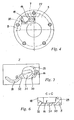
- the side with the opening worm groove is opposite side of the contour of the recording additionally with a hardened inlet radius to make it easier to snap into place of the locking pin formed in the receptacle, while the Corners of the contour with a diameter adapted to the locking pin Radius are rounded.
- the reason for the admission also points two different depths, of which the upper level serves as a stop surface designed for the receiving end face of the locking pin is.
- the lower level of the reason for inclusion worked into the upper level shows a transition to the confluent worm groove and is for supplying the hydraulic pressure medium to the end face of the locking pin intended.
- the merging worm groove is preferred a square or approximate square cross section and is with a smaller depth than the inclusion in the side wall of the drive wheel incorporated.
- other suitable cross sections are also conceivable here for the worm groove and / or an equal or even in the lower one Level of recording passing depth of worm groove.
- the surface area is larger than a defined play the cross-sectional area of the locking pin formed contour of the receptacle serves on the one hand to balance the radial bearing play between that on the radial end faces of the boundary walls of the drive wheel mounted impeller and the drive wheel and on the other hand the compensation of manufacturing-related position tolerances between the locking pin in the wheel hub of the impeller and its inclusion in the side wall of the drive wheel in both the radial and circumferential directions Contraption.
- the enlarged image enables optimal play for the locking pin when mounting the device to prevent jamming of the locking pin in the holder avoid.
- the inventive device for changing the timing of gas exchange valves of an internal combustion engine in particular a rotary piston adjusting device for adjusting the angle of rotation of a camshaft with respect to a crankshaft thus points towards those from the prior art Technology known devices have the advantage of being relocated the locking of a wing of the impeller in the wheel hub of the impeller or by significantly reducing the distance between the Longitudinal axis of the lock and the longitudinal central axis of the device on the one hand the stiffness of the locked connection between the impeller and the drive wheel significantly increased and on the other hand that in motor operation centrifugal forces acting on the locking pin can be significantly reduced.
- the lock Since the lock is no longer in the area of the pressure chambers Device and outside of the pressure medium lines to these pressure chambers is arranged, are both due to centrifugal force and due to accumulating Dirt particles in the hydraulic pressure medium due to malfunctions locking almost impossible. It is also possible the blades of the impeller are less solid, for example in plate form train and thus reduce the manufacturing costs of the device and to increase the number of possible work spaces in the device.
- the device designed according to the invention has the advantage that the locking pin is uniformly cylindrical over its entire length is simple and inexpensive to manufacture and a low Has space requirements, so that the manufacturing cost of the device still be further reduced and the device even in confined spaces is universally applicable in the engine compartment.
- the special execution of the recording of the locking pin and in operative connection with the receptacle standing face of the locking pin are the cause of that no more component loads between the impeller when locking and the drive wheel of the device occur and that when unlocking jamming of the locking pin in the receptacle no longer is possible.
- connection of the lock pin has only with one of the device's A pressure chambers the special one
- the device is specifically locked when it is switched off the internal combustion engine is possible. Because when the engine is turned off and thus the pressure medium pressure when the control valve of the device is de-energized bears on the B pressure chambers of the device, the impeller mostly while minimizing the volume of the respective A pressure chambers of the device in the base position necessary for starting the internal combustion engine twisted, in which the locking pin then reliably locks.
- the device designed according to the invention is thus both on intake camshafts with locking in “later” timing position the gas exchange valves as well as with exhaust camshafts and on SOHC engines with locking in “earlier” timing position of the gas exchange valves used.
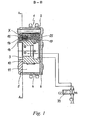
- FIG. 1 and 2 clearly show a device 1 for changing the Control times of gas exchange valves of an internal combustion engine, which as Rotary piston adjusting device for adjusting the angle of rotation of a not shown Camshaft compared to a crankshaft, also not shown an internal combustion engine is formed.
- This device 1 is on the drive side End of one in the cylinder head of the internal combustion engine Camshaft attached and designed in principle as a hydraulic actuator, depending on various operating parameters of the internal combustion engine is controlled by the hydraulic valve designated 33 in FIG.
- the device 1 in FIG Essentially from a drive connection with the crankshaft of the internal combustion engine stationary drive wheel 2 and from a rotationally fixed with the camshaft the internal combustion engine connected impeller 3, which Impeller 3 is pivotally mounted in the drive wheel 2 and with this in drive connection stands.
- the drive wheel 2 has one through a hollow cylindrical Circumferential wall 4 and two side walls 5, 6 formed cavity on, in the direction directed by five to the longitudinal central axis of the device 1 radial Boundary walls 7 and 8 five evenly distributed hydraulic Workrooms 9 are formed.
- the impeller 3 of the device 1 has accordingly on the circumference of his wheel hub 10 five evenly circumferentially distributed and each radially into a working space 9 of the drive wheel 2 extending wing 11, which each of the working spaces 9 in an A pressure chamber Subdivide 12 and a B-pressure chamber 13, which at optional or simultaneous pressurization with a hydraulic pressure medium Pivotal movement or fixation of the impeller 3 relative to the drive wheel 2 and thus an angle of rotation adjustment or hydraulic clamping cause the camshaft to the crankshaft.
- the device 1 for Avoidance of one resulting from the alternating torques of the camshaft Rattling of the impeller 3 at the start of the internal combustion engine has a separate locking element 14 with which the impeller 3 Falling below a pressure medium pressure required for adjustment in a preferred base position within its adjustment range with the drive wheel 2 can be coupled mechanically.
- This locking element 14 is in a bore parallel to the longitudinal center axis of the device 1 in the impeller 3 arranged and by a spring element 15 in a locking position slidable within a receptacle 16 in the side wall 5 of the drive wheel 2.
- FIGS. 1 to 3 show that the Locking element 14 according to the invention than over its entire length evenly cylindrical locking pin is formed in a continuous Axial bore 17 arranged in the wheel hub 10 of the impeller 3 is.
- Figure 2 it can be clearly seen that the longitudinal axis of this axial bore 17 the smallest possible distance to the longitudinal central axis of the device 1, around the centrifugal forces that arise during engine operation to minimize the locking element 14.
- FIG 3 A "sticking" of the locking element due to adhesive forces 14 in the receptacle 16 is additionally shown in FIG 3 visible hollow design of the front end face 21 of the locking element 14 avoided.
- Locking element 14 On its rear end face 22 that Locking element 14, on the other hand, has a basic bore 23 in which, as can also be seen from Figure 3, the one end of the pressure coil spring trained spring element 15 is fixed.
- the other end of this Spring element 15 is supported on one inserted into the axial bore 17 and formed with a centering tip 24 counterholder 15, the has a Y-shaped profile cross section and in which the between its Profile legs formed longitudinal grooves 26 at the same time for pressure medium ventilation the axial bore 17 are provided.
- the receptacle 16 of the locking element 14 which can be seen in FIG. 4 has furthermore according to the invention a quadrangular and in its area by one Defined all-round play larger than the cross-sectional area of the locking element 14 trained contour and is with a confluence Worm groove 18 formed exclusively with one in the locked position unpressurized A pressure chamber 12 of the device 1 is connected. This is ensures that the receptacle 16 of the locking element 14 only at Pressurizing the A pressure chambers 12 of the device 1 via the Worm groove 18 pressurized with the pressure of the hydraulic pressure medium and thus the locking element 14 is moved into its unlocked position.
- the upper level 30 is a stop surface of the locking pin 14 formed in the receptacle 16 while the lower level 31 incorporated into the upper level 30 has a transition 32 to the confluent worm groove 18 and to supply the hydraulic Pressure medium to the end face 21 of the locking element 14 is provided.
Landscapes
- Engineering & Computer Science (AREA)
- Mechanical Engineering (AREA)
- General Engineering & Computer Science (AREA)
- Valve Device For Special Equipments (AREA)
- Valve-Gear Or Valve Arrangements (AREA)
Applications Claiming Priority (2)
| Application Number | Priority Date | Filing Date | Title |
|---|---|---|---|
| DE10150856 | 2001-10-15 | ||
| DE10150856A DE10150856B4 (de) | 2001-10-15 | 2001-10-15 | Vorrichtung zum Verändern der Steuerzeiten von Gaswechselventilen einer Brennkraftmaschine, insbesondere Rotationskolben-Verstelleinrichtung zur Drehwinkelverstellung einer Nockenwelle gegenüber einer Kurbelwelle |
Publications (3)
| Publication Number | Publication Date |
|---|---|
| EP1302630A2 true EP1302630A2 (fr) | 2003-04-16 |
| EP1302630A3 EP1302630A3 (fr) | 2003-11-26 |
| EP1302630B1 EP1302630B1 (fr) | 2009-05-06 |
Family
ID=7702573
Family Applications (1)
| Application Number | Title | Priority Date | Filing Date |
|---|---|---|---|
| EP02020920A Expired - Lifetime EP1302630B1 (fr) | 2001-10-15 | 2002-09-19 | Dispositif pour déphaser les soupapes d'échange de gaz d'un moteur à combustion interne, notamment déphaseur à piston rotatif pour déphaser un arbre à cames relativement au vilebrequin |
Country Status (5)
| Country | Link |
|---|---|
| US (1) | US6805080B2 (fr) |
| EP (1) | EP1302630B1 (fr) |
| JP (1) | JP2003120231A (fr) |
| DE (2) | DE10150856B4 (fr) |
| ES (1) | ES2324598T3 (fr) |
Cited By (6)
| Publication number | Priority date | Publication date | Assignee | Title |
|---|---|---|---|---|
| WO2008006685A1 (fr) * | 2006-07-08 | 2008-01-17 | Schaeffler Kg | Dispositif destiné à réguler de manière variable les temps de commande de soupapes d'échanges des gaz d'un moteur à combustion interne |
| EP1589196A3 (fr) * | 2004-04-23 | 2008-08-06 | Bayerische Motoren Werke Aktiengesellschaft | Dispositif hydraulique pour la variation continue du calage d'arbre à cames |
| EP1607590A3 (fr) * | 2004-06-15 | 2008-10-15 | Schaeffler KG | Moteur muni d'un déphaseur d'arbre à cames hydraulique |
| WO2014154176A1 (fr) * | 2013-03-28 | 2014-10-02 | Shenzhen Byd Auto R & D Company Limited | Dispositif de commande de la position d'un vilebrequin, et moteur comprenant ce dispositif |
| WO2015140267A1 (fr) * | 2014-03-20 | 2015-09-24 | Gkn Sinter Metals Engineering Gmbh | Déphaseur d'arbre à cames variable comprenant une rondelle de verrouillage, rondelle de verrouillage et procédé de fabrication de ceux-ci |
| US20230279789A1 (en) * | 2022-03-03 | 2023-09-07 | Schaeffler Technologies AG & Co. KG | Contaminant pathway for camshaft phaser |
Families Citing this family (24)
| Publication number | Priority date | Publication date | Assignee | Title |
|---|---|---|---|---|
| DE10332881A1 (de) | 2003-07-19 | 2005-02-10 | Ina-Schaeffler Kg | Vorrichtung zum Verändern der Steuerzeiten von Gaswechselventilen einer Brennkraftmaschine, insbesondere Rotationskolben-Verstelleinrichtung zur Drehwinkelverstellung einer Nockenwelle gegenüber einer Kurbelwelle |
| DE10354586A1 (de) * | 2003-11-21 | 2005-06-16 | Ina-Schaeffler Kg | Hydraulischer Nockenwellenversteller und Verfahren zum Betreiben desselben |
| DE10355502A1 (de) * | 2003-11-27 | 2005-06-23 | Ina-Schaeffler Kg | Vorrichtung zum Verändern der Steuerzeiten von Gaswechselventilen einer Brennkraftmaschine, insbesondere Rotationskolben-Verstelleinrichtung zur Drehwinkelverstellung einer Nockenwelle gegenüber einer Kurbelwelle |
| US7178495B2 (en) * | 2003-12-19 | 2007-02-20 | Hydraulik-Ring Gmbh | Adjusting device for camshafts, particularly for motor vehicles |
| US6948467B2 (en) * | 2004-02-27 | 2005-09-27 | Delphi Technologies, Inc. | Locking pin mechanism for a vane-type cam phaser |
| DE102004022097A1 (de) | 2004-05-05 | 2005-12-08 | Daimlerchrysler Ag | Hydraulischer Nockenwellenversteller und Verfahren zur Montage desselben |
| DE102009041755B4 (de) * | 2008-10-09 | 2019-02-21 | Schaeffler Technologies AG & Co. KG | Doppeltes unabhängiges Verstellsystem zum unabhängigen Verstellen der Ansaug- und der Ausstoßnockenerhebungen einer konzentrischen Nockenwellenanordnung |
| DE102009041873A1 (de) | 2008-10-09 | 2010-04-15 | Schaeffler Kg | Nockenwellenversteller für die innere Nockenwelle eines konzentrischen Nockenwellenaufbaus |
| DE102010015716A1 (de) | 2009-04-24 | 2010-10-28 | Schaeffler Technologies Gmbh & Co. Kg | Integriertes Innennockenwellenschieberventil |
| DE102009030201A1 (de) | 2009-06-24 | 2010-12-30 | Schaeffler Technologies Gmbh & Co. Kg | Vorrichtung zur variablen Einstellung der Steuerzeiten von Gaswechselventilen einer Brennkraftmaschine |
| BR112012013112A2 (pt) | 2009-12-11 | 2017-03-28 | Schaeffler Technologies Ag | rotor escalonado para faseador de eixo de comando de válvulas |
| DE102011004539A1 (de) * | 2011-02-22 | 2012-08-23 | Schwäbische Hüttenwerke Automotive GmbH | Nockenwellen-Phasensteller mit verbesserter Verriegelungseinrichtung |
| DE102012200756A1 (de) * | 2012-01-19 | 2013-07-25 | Schaeffler Technologies AG & Co. KG | Gebauter Kunststoffrotor mit integrierter Patrone und Federeinhängung |
| WO2013128295A2 (fr) | 2012-02-28 | 2013-09-06 | Schaeffler Technologies AG & Co. KG | Mise en phase électrique d'un arbre à cames concentrique |
| DE102013219406A1 (de) | 2012-09-28 | 2014-04-03 | Denso Corporation | Ventilzeiteinstellungssteuerungsgerät |
| JP5967137B2 (ja) | 2013-07-31 | 2016-08-10 | 株式会社デンソー | バルブタイミング調整装置 |
| DE102014216119A1 (de) | 2013-08-22 | 2015-02-26 | Schaeffler Technologies Gmbh & Co. Kg | Verfahren und Vorrichtung zum Wickeln einer Rückstellfeder mit einem zweiteiligen Rotor für einen Nockenversteller |
| DE102014205103B4 (de) * | 2014-03-19 | 2020-11-26 | Schaeffler Technologies AG & Co. KG | Nockenwellenversteller |
| US9341089B2 (en) | 2014-04-04 | 2016-05-17 | RB Distribution, Inc. | Camshaft phaser |
| DE102014008155A1 (de) | 2014-05-30 | 2015-12-17 | Daimler Ag | Nockenwellenverstellvorrichtung |
| US9797277B2 (en) | 2015-02-20 | 2017-10-24 | Schaeffler Technologies AG & Co. KG | Camshaft phaser |
| DE102018128865A1 (de) | 2018-11-16 | 2020-05-20 | Schaeffler Technologies AG & Co. KG | Hydraulischer Nockenwellenversteller |
| CN111659958B (zh) * | 2020-06-17 | 2024-05-07 | 深圳市领时机械有限公司 | 一种用于小孔内侧壁径向孔的动力倒角装置 |
| DE112020007519T5 (de) * | 2020-08-20 | 2023-06-22 | Schaeffler Technologies AG & Co. KG | Nockenphasenversteller |
Citations (1)
| Publication number | Priority date | Publication date | Assignee | Title |
|---|---|---|---|---|
| DE19623818A1 (de) | 1995-06-14 | 1996-12-19 | Nippon Denso Co | Steuervorrichtung zum Variieren einer Dreh- oder Winkelphase zwischen zwei drehenden Wellen, vorzugsweise anwendbar auf eine Ventilsteuerzeiten-Steuervorrichtung für einen Verbrennungsmotor |
Family Cites Families (8)
| Publication number | Priority date | Publication date | Assignee | Title |
|---|---|---|---|---|
| JPH1150820A (ja) * | 1997-08-05 | 1999-02-23 | Toyota Motor Corp | 内燃機関のバルブタイミング制御装置 |
| JPH11218014A (ja) * | 1998-02-03 | 1999-08-10 | Toyota Motor Corp | 可変バルブタイミング装置 |
| DE19929393A1 (de) * | 1999-06-26 | 2000-12-28 | Schaeffler Waelzlager Ohg | Verfahren zur Ansteuerung einer Vorrichtung zum Variieren der Ventilsteuerzeiten einer Brennkraftmaschine, insbesondere einer Nockenwellen-Verstelleinrichtung mit hydraulisch entriegelbarer Startverriegelung |
| JP4203703B2 (ja) * | 2000-06-14 | 2009-01-07 | アイシン精機株式会社 | 弁開閉時期制御装置 |
| JP3983457B2 (ja) * | 2000-06-22 | 2007-09-26 | 株式会社日立製作所 | 内燃機関のバルブタイミング変更装置 |
| JP4802394B2 (ja) * | 2000-08-03 | 2011-10-26 | アイシン精機株式会社 | 弁開閉時期制御装置 |
| US6374788B1 (en) * | 2000-12-25 | 2002-04-23 | Mitsubishi Denki Kabushiki Kaisha | Valve timing control device |
| US6460496B2 (en) * | 2000-12-25 | 2002-10-08 | Mitsubishi Denki Kabushiki Kaisha | Valve timing control device |
-
2001
- 2001-10-15 DE DE10150856A patent/DE10150856B4/de not_active Expired - Lifetime
-
2002
- 2002-09-19 ES ES02020920T patent/ES2324598T3/es not_active Expired - Lifetime
- 2002-09-19 DE DE50213520T patent/DE50213520D1/de not_active Expired - Lifetime
- 2002-09-19 EP EP02020920A patent/EP1302630B1/fr not_active Expired - Lifetime
- 2002-10-11 JP JP2002299352A patent/JP2003120231A/ja active Pending
- 2002-10-15 US US10/270,824 patent/US6805080B2/en not_active Expired - Lifetime
Patent Citations (1)
| Publication number | Priority date | Publication date | Assignee | Title |
|---|---|---|---|---|
| DE19623818A1 (de) | 1995-06-14 | 1996-12-19 | Nippon Denso Co | Steuervorrichtung zum Variieren einer Dreh- oder Winkelphase zwischen zwei drehenden Wellen, vorzugsweise anwendbar auf eine Ventilsteuerzeiten-Steuervorrichtung für einen Verbrennungsmotor |
Cited By (9)
| Publication number | Priority date | Publication date | Assignee | Title |
|---|---|---|---|---|
| EP1589196A3 (fr) * | 2004-04-23 | 2008-08-06 | Bayerische Motoren Werke Aktiengesellschaft | Dispositif hydraulique pour la variation continue du calage d'arbre à cames |
| EP1607590A3 (fr) * | 2004-06-15 | 2008-10-15 | Schaeffler KG | Moteur muni d'un déphaseur d'arbre à cames hydraulique |
| WO2008006685A1 (fr) * | 2006-07-08 | 2008-01-17 | Schaeffler Kg | Dispositif destiné à réguler de manière variable les temps de commande de soupapes d'échanges des gaz d'un moteur à combustion interne |
| US8047170B2 (en) | 2006-07-08 | 2011-11-01 | Schaeffler Technologies Gmbh & Co. Kg | Device for variably adjusting control times of gas exchange valves of an internal combustion engine |
| WO2014154176A1 (fr) * | 2013-03-28 | 2014-10-02 | Shenzhen Byd Auto R & D Company Limited | Dispositif de commande de la position d'un vilebrequin, et moteur comprenant ce dispositif |
| WO2015140267A1 (fr) * | 2014-03-20 | 2015-09-24 | Gkn Sinter Metals Engineering Gmbh | Déphaseur d'arbre à cames variable comprenant une rondelle de verrouillage, rondelle de verrouillage et procédé de fabrication de ceux-ci |
| US10294832B2 (en) | 2014-03-20 | 2019-05-21 | Gkn Sinter Metals Engineering Gmbh | Variable camshaft adjuster with locking disc, locking disc, and method for producing same |
| US20230279789A1 (en) * | 2022-03-03 | 2023-09-07 | Schaeffler Technologies AG & Co. KG | Contaminant pathway for camshaft phaser |
| US11994043B2 (en) * | 2022-03-03 | 2024-05-28 | Schaeffler Technologies AG & Co. KG | Contaminant pathway for camshaft phaser |
Also Published As
| Publication number | Publication date |
|---|---|
| JP2003120231A (ja) | 2003-04-23 |
| EP1302630A3 (fr) | 2003-11-26 |
| EP1302630B1 (fr) | 2009-05-06 |
| US20030084863A1 (en) | 2003-05-08 |
| ES2324598T3 (es) | 2009-08-11 |
| DE10150856A1 (de) | 2003-04-24 |
| DE10150856B4 (de) | 2005-08-11 |
| DE50213520D1 (de) | 2009-06-18 |
| US6805080B2 (en) | 2004-10-19 |
Similar Documents
| Publication | Publication Date | Title |
|---|---|---|
| EP1302630B1 (fr) | Dispositif pour déphaser les soupapes d'échange de gaz d'un moteur à combustion interne, notamment déphaseur à piston rotatif pour déphaser un arbre à cames relativement au vilebrequin | |
| EP2470756B1 (fr) | Vanne de commande | |
| DE112009004393B4 (de) | Steuerventil für eine Vorrichtung zur variablen Einstellung der Steuerzeiten von Gaswechselventilen einer Brennkraftmaschine | |
| EP2220345B1 (fr) | Dispositif de réglage variable de la distribution de soupapes de renouvellement des gaz d'un moteur à combustion interne | |
| DE10134320A1 (de) | Vorrichtung zum Verändern der Steuerzeiten von Gaswechselventilen einer Brennkraftmaschine, insbesondere Rotationskolben-Verstelleinrichtung zur Drehwinkelverstellung einer Nockenwelle gegenüber einer Kurbelwelle | |
| EP2470757B1 (fr) | Vanne de commande | |
| EP2041402B1 (fr) | Dispositif destiné à régler de manière variable les temps de commande des soupapes d'échanges des gaz d'un moteur à combustion interne | |
| EP1492943B1 (fr) | Dispositif pour modifier la distribution des soupapes d'echange gazeux d'un moteur a combustion interne, notamment dispositif de reglage hydraulique d'angle de rotation d'un arbre a cames relativement a un vilebrequin | |
| DE102016114978A1 (de) | Pleuel für eine Brennkraftmaschine mit variabler Verdichtung | |
| EP2536926A1 (fr) | Roue à aubes d'un dispositif pour l'ajustement variable des temps de commande de soupapes d'échange gazeux d'un moteur à combustion interne | |
| WO2005049976A1 (fr) | Dispositif de reglage hydraulique d'arbre a cames et procede permettant de faire fonctionner ledit dispositif | |
| DE102008019746A1 (de) | Vorrichtung zur variablen Einstellung der Steuerzeiten von Gaswechselventilen einer Brennkraftmaschine | |
| DE102007019920A1 (de) | Verrieglungs- und Drehwinkelbegrenzungsanordnung eines Nockenwellenverstellers | |
| DE102008051755A1 (de) | Vorrichtung zur variablen Einstellung der Steuerzeiten von Gaswechselventilen einer Brennkraftmaschine | |
| EP1706604B1 (fr) | Dispositif pour modifier les temps de commande de soupapes d'echange gazeux d'un moteur a combustion interne, en particulier un dispositif d'ajustement de pistons de rotation permettant un ajustage de l'angle de rotation entre un arbre a cames et un vilebrequin | |
| DE19861252B4 (de) | Vorrichtung zum Verändern der Steuerzeiten von Gaswechselventilen einer Brennkraftmaschine, insbesondere Rotationskolben-Verstelleinrichtung zur Drehwinkelverstellung einer Nockenwelle gegenüber einer Kurbelwelle | |
| EP1646769B1 (fr) | Dispositif de modification des temps de commande de soupapes d'echange gazeux d'un moteur a combustion interne, notamment d'un dispositif de reglage d'un piston rotatif permettant le reglage angulaire de rotation d'un arbre a cames par rapport a un vilebrequin | |
| DE10253883A1 (de) | Verstelleinrichtung für Nockenwellen, insbesondere von Kraftfahrzeugen | |
| EP2362074B1 (fr) | Dispositif destiné au calage variable des soupapes d'un moteur à combustion interne | |
| DE10081875B4 (de) | Verfahren zur Ansteuerung einer Vorrichtung zum Variieren der Ventilsteuerzeiten einer Brennkraftmaschine, insbesondere einer Nockenwellen-Verstelleinrichtung mit hydraulisch entriegelbarer Startverriegelung | |
| DE10013877A1 (de) | Vorrichtung zum Verändern der Steuerzeiten von Gaswechselventilen einer Brennkraftmaschine | |
| DE102015106230A1 (de) | Schwenkmotorversteller für eine Nockenwelle | |
| DE10013479A1 (de) | Vorrichtung zum Variieren der Ventilsteuerzeiten einer Brennkraftmaschine | |
| EP1180582B1 (fr) | Dispositif variateur de phase entre un arbre à cames et une roue d'entraInement, pour moteur à combustion interne | |
| DE4204048A1 (de) | Nockenwellenanordnung mit zumindest einem desaktivierbaren nocken |
Legal Events
| Date | Code | Title | Description |
|---|---|---|---|
| PUAI | Public reference made under article 153(3) epc to a published international application that has entered the european phase |
Free format text: ORIGINAL CODE: 0009012 |
|
| 17P | Request for examination filed |
Effective date: 20020919 |
|
| AK | Designated contracting states |
Designated state(s): AT BE BG CH CY CZ DE DK EE ES FI FR GB GR IE IT LI LU MC NL PT SE SK TR |
|
| AX | Request for extension of the european patent |
Extension state: AL LT LV MK RO SI |
|
| PUAL | Search report despatched |
Free format text: ORIGINAL CODE: 0009013 |
|
| AK | Designated contracting states |
Kind code of ref document: A3 Designated state(s): AT BE BG CH CY CZ DE DK EE ES FI FR GB GR IE IT LI LU MC NL PT SE SK TR |
|
| AX | Request for extension of the european patent |
Extension state: AL LT LV MK RO SI |
|
| AKX | Designation fees paid |
Designated state(s): DE ES FR IT SE |
|
| RAP1 | Party data changed (applicant data changed or rights of an application transferred) |
Owner name: SCHAEFFLER KG |
|
| 17Q | First examination report despatched |
Effective date: 20070924 |
|
| GRAP | Despatch of communication of intention to grant a patent |
Free format text: ORIGINAL CODE: EPIDOSNIGR1 |
|
| GRAS | Grant fee paid |
Free format text: ORIGINAL CODE: EPIDOSNIGR3 |
|
| GRAA | (expected) grant |
Free format text: ORIGINAL CODE: 0009210 |
|
| AK | Designated contracting states |
Kind code of ref document: B1 Designated state(s): DE ES FR IT SE |
|
| REF | Corresponds to: |
Ref document number: 50213520 Country of ref document: DE Date of ref document: 20090618 Kind code of ref document: P |
|
| REG | Reference to a national code |
Ref country code: ES Ref legal event code: FG2A Ref document number: 2324598 Country of ref document: ES Kind code of ref document: T3 |
|
| REG | Reference to a national code |
Ref country code: SE Ref legal event code: TRGR |
|
| REG | Reference to a national code |
Ref country code: FR Ref legal event code: GC |
|
| PLBE | No opposition filed within time limit |
Free format text: ORIGINAL CODE: 0009261 |
|
| STAA | Information on the status of an ep patent application or granted ep patent |
Free format text: STATUS: NO OPPOSITION FILED WITHIN TIME LIMIT |
|
| 26N | No opposition filed |
Effective date: 20100209 |
|
| PGFP | Annual fee paid to national office [announced via postgrant information from national office to epo] |
Ref country code: IT Payment date: 20100930 Year of fee payment: 9 |
|
| PGFP | Annual fee paid to national office [announced via postgrant information from national office to epo] |
Ref country code: FR Payment date: 20111012 Year of fee payment: 10 Ref country code: SE Payment date: 20110929 Year of fee payment: 10 |
|
| REG | Reference to a national code |
Ref country code: ES Ref legal event code: PC2A Owner name: SCHAEFFLER TECHNOLOGIES AG & CO.KG Effective date: 20120806 |
|
| REG | Reference to a national code |
Ref country code: DE Ref legal event code: R081 Ref document number: 50213520 Country of ref document: DE Owner name: SCHAEFFLER TECHNOLOGIES AG & CO. KG, DE Free format text: FORMER OWNER: SCHAEFFLER TECHNOLOGIES GMBH & CO. KG, 91074 HERZOGENAURACH, DE Effective date: 20120828 Ref country code: DE Ref legal event code: R081 Ref document number: 50213520 Country of ref document: DE Owner name: SCHAEFFLER TECHNOLOGIES GMBH & CO. KG, DE Free format text: FORMER OWNER: SCHAEFFLER TECHNOLOGIES GMBH & CO. KG, 91074 HERZOGENAURACH, DE Effective date: 20120828 |
|
| REG | Reference to a national code |
Ref country code: FR Ref legal event code: TP Owner name: SCHAEFFLER TECHNOLOGIES AG & CO. KG, DE Effective date: 20121022 Ref country code: FR Ref legal event code: RG Effective date: 20121022 Ref country code: FR Ref legal event code: CJ Effective date: 20121022 Ref country code: FR Ref legal event code: CD Owner name: SCHAEFFLER TECHNOLOGIES AG & CO. KG, DE Effective date: 20121022 |
|
| PG25 | Lapsed in a contracting state [announced via postgrant information from national office to epo] |
Ref country code: SE Free format text: LAPSE BECAUSE OF NON-PAYMENT OF DUE FEES Effective date: 20120920 |
|
| REG | Reference to a national code |
Ref country code: SE Ref legal event code: EUG |
|
| REG | Reference to a national code |
Ref country code: FR Ref legal event code: ST Effective date: 20130531 |
|
| PG25 | Lapsed in a contracting state [announced via postgrant information from national office to epo] |
Ref country code: FR Free format text: LAPSE BECAUSE OF NON-PAYMENT OF DUE FEES Effective date: 20121001 Ref country code: IT Free format text: LAPSE BECAUSE OF NON-PAYMENT OF DUE FEES Effective date: 20120919 |
|
| REG | Reference to a national code |
Ref country code: DE Ref legal event code: R081 Ref document number: 50213520 Country of ref document: DE Owner name: SCHAEFFLER TECHNOLOGIES GMBH & CO. KG, DE Free format text: FORMER OWNER: SCHAEFFLER TECHNOLOGIES AG & CO. KG, 91074 HERZOGENAURACH, DE Effective date: 20140214 Ref country code: DE Ref legal event code: R081 Ref document number: 50213520 Country of ref document: DE Owner name: SCHAEFFLER TECHNOLOGIES AG & CO. KG, DE Free format text: FORMER OWNER: SCHAEFFLER TECHNOLOGIES AG & CO. KG, 91074 HERZOGENAURACH, DE Effective date: 20140214 |
|
| REG | Reference to a national code |
Ref country code: DE Ref legal event code: R081 Ref document number: 50213520 Country of ref document: DE Owner name: SCHAEFFLER TECHNOLOGIES AG & CO. KG, DE Free format text: FORMER OWNER: SCHAEFFLER TECHNOLOGIES GMBH & CO. KG, 91074 HERZOGENAURACH, DE Effective date: 20150211 |
|
| REG | Reference to a national code |
Ref country code: ES Ref legal event code: PC2A Owner name: SCHAEFFLER TECHNOLOGIES AG & CO.KG Effective date: 20150512 |
|
| PGFP | Annual fee paid to national office [announced via postgrant information from national office to epo] |
Ref country code: ES Payment date: 20211119 Year of fee payment: 20 Ref country code: DE Payment date: 20211118 Year of fee payment: 20 |
|
| REG | Reference to a national code |
Ref country code: DE Ref legal event code: R071 Ref document number: 50213520 Country of ref document: DE |
|
| REG | Reference to a national code |
Ref country code: ES Ref legal event code: FD2A Effective date: 20220928 |
|
| PG25 | Lapsed in a contracting state [announced via postgrant information from national office to epo] |
Ref country code: ES Free format text: LAPSE BECAUSE OF EXPIRATION OF PROTECTION Effective date: 20220920 |
|
| P01 | Opt-out of the competence of the unified patent court (upc) registered |
Effective date: 20230522 |