EP1302670A2 - Lüftermontageanordnung - Google Patents
Lüftermontageanordnung Download PDFInfo
- Publication number
- EP1302670A2 EP1302670A2 EP03075277A EP03075277A EP1302670A2 EP 1302670 A2 EP1302670 A2 EP 1302670A2 EP 03075277 A EP03075277 A EP 03075277A EP 03075277 A EP03075277 A EP 03075277A EP 1302670 A2 EP1302670 A2 EP 1302670A2
- Authority
- EP
- European Patent Office
- Prior art keywords
- fan
- mounting arrangement
- hub
- blade
- mounting
- Prior art date
- Legal status (The legal status is an assumption and is not a legal conclusion. Google has not performed a legal analysis and makes no representation as to the accuracy of the status listed.)
- Granted
Links
- 230000008878 coupling Effects 0.000 claims description 3
- 238000010168 coupling process Methods 0.000 claims description 3
- 238000005859 coupling reaction Methods 0.000 claims description 3
- 238000000034 method Methods 0.000 claims description 3
- 230000002035 prolonged effect Effects 0.000 claims description 2
- 239000004033 plastic Substances 0.000 description 8
- 229920003023 plastic Polymers 0.000 description 8
- 230000002093 peripheral effect Effects 0.000 description 7
- 230000007423 decrease Effects 0.000 description 6
- 238000001816 cooling Methods 0.000 description 5
- 230000001965 increasing effect Effects 0.000 description 5
- 230000004048 modification Effects 0.000 description 3
- 238000012986 modification Methods 0.000 description 3
- 230000001154 acute effect Effects 0.000 description 2
- 230000000994 depressogenic effect Effects 0.000 description 2
- 238000011144 upstream manufacturing Methods 0.000 description 2
- 230000005534 acoustic noise Effects 0.000 description 1
- 230000015572 biosynthetic process Effects 0.000 description 1
- 239000000428 dust Substances 0.000 description 1
- 230000000694 effects Effects 0.000 description 1
- 230000008030 elimination Effects 0.000 description 1
- 238000003379 elimination reaction Methods 0.000 description 1
- 230000002708 enhancing effect Effects 0.000 description 1
- 238000001746 injection moulding Methods 0.000 description 1
- 238000004519 manufacturing process Methods 0.000 description 1
- 239000000463 material Substances 0.000 description 1
- 239000007769 metal material Substances 0.000 description 1
- 239000002991 molded plastic Substances 0.000 description 1
- 238000000465 moulding Methods 0.000 description 1
- 238000004806 packaging method and process Methods 0.000 description 1
- 230000003134 recirculating effect Effects 0.000 description 1
- 230000000717 retained effect Effects 0.000 description 1
- 239000007787 solid Substances 0.000 description 1
Images


Classifications
-
- F—MECHANICAL ENGINEERING; LIGHTING; HEATING; WEAPONS; BLASTING
- F04—POSITIVE - DISPLACEMENT MACHINES FOR LIQUIDS; PUMPS FOR LIQUIDS OR ELASTIC FLUIDS
- F04D—NON-POSITIVE-DISPLACEMENT PUMPS
- F04D29/00—Details, component parts, or accessories
- F04D29/26—Rotors specially for elastic fluids
- F04D29/32—Rotors specially for elastic fluids for axial flow pumps
- F04D29/38—Blades
- F04D29/384—Blades characterised by form
- F04D29/386—Skewed blades
-
- F—MECHANICAL ENGINEERING; LIGHTING; HEATING; WEAPONS; BLASTING
- F04—POSITIVE - DISPLACEMENT MACHINES FOR LIQUIDS; PUMPS FOR LIQUIDS OR ELASTIC FLUIDS
- F04D—NON-POSITIVE-DISPLACEMENT PUMPS
- F04D19/00—Axial-flow pumps
- F04D19/002—Axial flow fans
-
- F—MECHANICAL ENGINEERING; LIGHTING; HEATING; WEAPONS; BLASTING
- F04—POSITIVE - DISPLACEMENT MACHINES FOR LIQUIDS; PUMPS FOR LIQUIDS OR ELASTIC FLUIDS
- F04D—NON-POSITIVE-DISPLACEMENT PUMPS
- F04D29/00—Details, component parts, or accessories
- F04D29/26—Rotors specially for elastic fluids
- F04D29/32—Rotors specially for elastic fluids for axial flow pumps
- F04D29/325—Rotors specially for elastic fluids for axial flow pumps for axial flow fans
- F04D29/326—Rotors specially for elastic fluids for axial flow pumps for axial flow fans comprising a rotating shroud
-
- F—MECHANICAL ENGINEERING; LIGHTING; HEATING; WEAPONS; BLASTING
- F04—POSITIVE - DISPLACEMENT MACHINES FOR LIQUIDS; PUMPS FOR LIQUIDS OR ELASTIC FLUIDS
- F04D—NON-POSITIVE-DISPLACEMENT PUMPS
- F04D29/00—Details, component parts, or accessories
- F04D29/26—Rotors specially for elastic fluids
- F04D29/32—Rotors specially for elastic fluids for axial flow pumps
- F04D29/325—Rotors specially for elastic fluids for axial flow pumps for axial flow fans
- F04D29/329—Details of the hub
-
- F—MECHANICAL ENGINEERING; LIGHTING; HEATING; WEAPONS; BLASTING
- F04—POSITIVE - DISPLACEMENT MACHINES FOR LIQUIDS; PUMPS FOR LIQUIDS OR ELASTIC FLUIDS
- F04D—NON-POSITIVE-DISPLACEMENT PUMPS
- F04D29/00—Details, component parts, or accessories
- F04D29/60—Mounting; Assembling; Disassembling
- F04D29/601—Mounting; Assembling; Disassembling specially adapted for elastic fluid pumps
Definitions
- the present invention relates to a mounting arrangement for an axial flow fan, for example a fan designed to cool air flowing through a heat exchange system in a vehicle.
- a fan When used in a vehicular application, a fan can be arranged either to blow air through a heat exchange system such as a radiator, if the heat exchange system is on the high-pressure (downstream) side of the fan or draw air through the heat exchange system if the heat exchange system is on the low-pressure (upstream) side of the fan.
- a heat exchange system such as a radiator
- the mounting of the fan is of particular concern when used to move air in an enclosed engine compartment. More particularly, the fan mounting is required to prevent noise and other vibrations from being transmitted between the rotating fan and the vehicle body work. Another requirement is that the mounting should, as far as possible, prevent air from leaking-back around the periphery of the fan.
- a first object of the present invention is to provide a fan mounting arrangement which is capable of providing an improved acoustic noise performance.
- a second object of the present invention is to provide minimum fan packaging while maintaining, or increasing, the fan system efficiency.
- a mounting arrangement for mounting an axial flow fan to a structure defining a circular passage, the mounting arrangement comprising plurality of arms extending from said structure for supporting said fan, wherein at least one arm has a longitudinal axis skewed with respect to a radius of the circular passage.
- the axial flow fan is secured to an electric drive motor for driving the fan, and the mounting arrangement supports the drive motor.
- a mounting arrangement for mounting an axial flow fan to a structure defining a circular passage comprising a plurality of arms extending from said structure for supporting said fan, the arms being spaced irregularly with respect to the circular passage whereby acoustic resonances are reduced.
- the axial flow fan is secured to an electric drive motor for driving the fan, and the mounting arrangement supports the drive motor.
- a mounting arrangement for mounting an axial flow fan to a support structure defining a passage, the arrangement comprising a plurality of arms extending from said support structure for supporting said fan, at least one arm having, at its support structure end, an attachment finger extending in use parallel to the plane of the fan for sliding cooperation with an attachment socket of said structure.
- the axial flow fan is secured to an electric drive motor for driving the fan, and the mounting arrangement supports the drive motor.
- a fan comprising plural blades and a bowl-shaped hub member having a front wall portion extending to a peripheral side wall portion and plural internal radially-extending vane member for circulating air within said hub member wherein each vane member has a first portion extending forwardly along the side wall portion and a second portion extending along the front wall.
- an electric fan comprising plural blades and a bowl-shaped hub member having a front wall portion extending to a peripheral side wall portion and plural internal radially-extending vane members for circulating air within said hub member wherein each vane member has a first portion extending forwardly along the side wall portion and a second portion extending along the front wall, and an electric motor for driving said fan, a portion of said motor being disposed within the hub member whereby in use the motor is cooled by circulation of air caused by said vane members.
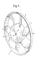
- Figures 1 and 2 show a fan 2 which has a centrally located cylindrical hub 4 with a plurality (seven as illustrated) of blades 6 extending radially outwardly therefrom to an outer band 8 having a generally cylindrical form.
- the hub 4 carries a central hub insert 10 which defines an aperture 12 for accepting a shaft which mounts the fan for rotation around its central axis.
- the outer band 8 encloses the blades and is generally centered on the axis of rotation of the fan 2.
- Each blade 6 extends from a root region 14 secured to the hub 4 to an outer (or tip) region 16 secured to the inner surface of the band 8.
- the tip region 16 of the blades 6 are joined to the band over the full width of the blades and not at a single point or over a narrow connecting line. This increases the strength of the structure.
- the outer band 8 of the fan adds structural strength to the fan by supporting the blades at their tip and also serves to hold air on the working surface of the blades.
- the band 8 is of uniform thickness and has a first axially extending cylindrical portion 9 and an axially extreme portion 9a which is curved radially outwardly to provide a bell-mouth, as is best seen in Figure 7.
- the curved portion 9a of the band 8 reduces losses due to vortices in a gap between the fan and a shroud member surrounding the fan.
- the band 8 furthermore provides a uniform flow passage of air flow passing through the fan and decreases unwanted variations in the dihedral angle u and the pitch angle (see Figure 6) of the blade by virtue of the tip support.
- the blades 6 have respective leading edges B and trailing edges C and are shaped so that they are secured to the band 8 with the leading edge B tangential to the curved portion 8a of the band. This can be seen in Figure 7.
- the fan can be positioned in front of or behind an engine cooling heat exchanger system comprising for example a radiator, condenser and oil cooler.
- the fan may be arranged so that air is either blown through the heat exchanger system if the heat exchanger is on the high pressure (downstream) side of the fan, or drawn through the heat exchanger system, if the exchanger is on the low pressure (upstream) side of the fan.
- the fan 2 is preferably used in conjunction with a shroud that extends between the radiator and the outer edge of the fan.
- the shroud serves to prevent recirculation of air around the outer edge of the fan from the high pressure region at the downstream side of the fan to the low pressure region at the opposite side of the fan adjacent the radiator.
- One known shroud structure is funnel-like as shown for example in US-A-4,358,245.
- a second shroud arrangement is shown in Figures 10-12, and will be described later herein.
- the hub has a plastics moulded body member 18 which defines an outer cylindrical hub ring 20 and an inner cylindrical hub ring 22.
- the inner and outer hub rings define between them an annular space 21.
- the inner cylindrical hub ring 22 has first and second axially spaced annular ledges 24 and 25 which are directed radially inwardly.
- the ledges are provided for supporting a hub insert 10 as described in more detail hereinafter.
- the hub insert 10 can be made of a plastics or metal material and is a body formed as a solid walled cylinder 26 having a plurality of peripheral circumferentially spaced protrusions 28 which form a castellated outer surface.
- the castellations may all be in the same plane perpendicular to the insert axis, or may be in different planes perpendicular to that axis.
- the insert 10 defines an aperture 12 having a first cylindrical portion and an adjoining portion in the form of a D shape, that is having an arcuate portion 30 and an opposing single flat portion 32.
- the flat portion 32 is for keying to a shaft inserted into the aperture 12 whereby rotation of the shaft with respect to the hub insert 10 is prevented.
- the castellated outer surface of the hub insert 10 enables the hub insert to be connected to the plastics moulded portion 18 of the hub in a single manufacturing step. That is, a mould defining the plastics moulded body portion 18 is provided in which the hub insert 10 is placed. Plastics material is injected into the mould in a known injection moulding process and enters between the protrusions 28 of the hub insert. Thus, a secure mechanical connection is provided between the hub insert 10 and the plastics moulded portion 18.
- the hub insert 10 provides a close fit and thus reduces the play between a shaft inserted into the aperture 12 and the insert 10. This thus helps preserve the fan balance when rotating and reduces drift of the fan from true axial rotation.
- annular space 21 between the inner and outer hub rings may accommodate the front face of an electrical motor provided to drive the shaft.
- the motor is then protected by the moulded portion from the intrusion of moisture and dust.
- the outer surface of the fan hub 4 approximates to a bowl shape which is more rounded than the straight cylindrical hubs of the prior art. More particularly, the hub outer surface has a central shallow depressed region 15 flanked by a substantially straight angled annular region 50. The annular region extends to a substantially planar annular region 52 which further extends into an outer cylindrical surface 55 of the hub via a radiussed portion 54. The elimination of a sharp angle at the front part of the hub reduces vortices forming at the hub surface. The formation of vortices, known as "vortex shedding" causes undesirable turbulence in the flow in the region of the hub, and gives rise to increased noise levels.
- the minimum extent of the hub in the axial direction is at least equal to the axial blade extent at the root of the blade 6.
- the axial extent of the hub 4 and of the outer band 8 respectively may vary up to 50% of the axial extent of the band 8.
- the inner surface of the hub moulded portion 18 is provided with a plurality of radially extending ribs, one of which can be seen in Figure 3 designated by reference numeral 19.
- the ribs 19 of which two are provided for each blade, are curved with the moulded plastics section 18 and serve to guide flow recirculating in the rear part of the hub in an effective manner to cool an electric motor by dissipating heat generated thereby.
- the ribs 19 extend radially inwardly towards the inner cylindrical ring 22 and thus also provide structural support for the hub body and hub insert.
- each blade 6 is rearwardly skewed in that the medial line of the blade (which is the line obtained by joining the points that are circumferentially equidistant from the leading edge B and the trailing edge C of the blade) is curved in a direction (root to tip) opposite to the direction D of rotation of the fan 2.
- the leading and trailing edges B,C are curved in the same direction.
- the skew is referred to herein as the tangential sweep of the blade and is indicated diagrammatically by the angles 1, 2 and 3 in Figure 8.
- each blade is secured to the hub so that the blade lies at a dihedral angle which is illustrated diagrammatically by angle u in Figure 6.
- the dihedral angle u is the angle between a tangent P-T to the blade surface and a plane P-Q perpendicular to the axis of rotation. Furthermore, the blade is pitched so that the leading and trailing edges B and C are not in the same plane.
- the pitch angle ⁇ alternatively known as the chord angle is also shown in Figure 6.
- Figure 7 shows in section the blade 6 and the connection at the root to the hub 4 and at the tip to the band 8.
- Figure 7 also shows a variation in the dihedral angle ⁇ such that the dihedral angle decreases with respect to the radius of the fan along the span of the blade over the first 50% of the innermost radius and then stays constant for the remaining 50%.
- the dihedral angle remaining constant over the remaining 50% of the blade span it could increase slightly over this distance.
- FIG. 8 the fan origin is indicated as O.
- the leading edge B of the blade contains a portion BI at which the tangent D to the curve passes through the origin.
- the medial line of the blade 6, shown as curve A has a point AI, at which the tangent x to the line passes through the origin, and the curve C defining the trailing edge has a similar portion CI extending tangentially to the radial line E.
- Figure 9 illustrates the relationship between the projection of the chord length at the root 14 of the blade and that at the tip 16.
- Ri is the radius of the hub measured from the fan origin O and ⁇ R is the angle subtended by the root points CR, BR of the trailing and leading edges.
- Points CT and BT are the trailing and leading edge tip points. Radii intersecting these tip points subtend an angle ⁇ t .
- ⁇ R is greater than ⁇ t .
- the chord length itself gradually increases from the root of the blade over the first 50% of the span of the blade. The chord length may then decrease over the whole remaining span, or decrease up to about 70% of the span, after which it remains constant.
- chord angle The angle that the blade chord makes with the horizontal axis.
- the chord angle decreases with respect to the radius of the fan, preferably along the entire blade length.
- the projected blade width gradually decreases from the root of the blade along the span of the blade, i.e. with increase of blade radius.
- the blade described herein provides a downstream variable axial flow velocity which increases continuously from the hub 4 to the outermost region of the blade, with the maximum axial velocities occurring over the span of the blade at the outermost 25-35% of the blade. This variation enables the performance efficiency of the fan to be optimised whilst reducing the noise level.
Landscapes
- Engineering & Computer Science (AREA)
- Mechanical Engineering (AREA)
- General Engineering & Computer Science (AREA)
- Structures Of Non-Positive Displacement Pumps (AREA)
Applications Claiming Priority (5)
| Application Number | Priority Date | Filing Date | Title |
|---|---|---|---|
| US31482794A | 1994-09-29 | 1994-09-29 | |
| US314827 | 1994-09-29 | ||
| US08/456,178 US5582507A (en) | 1994-09-29 | 1995-05-31 | Automotive fan structure |
| US456178 | 1995-05-31 | ||
| EP95306851.7A EP0704626B2 (de) | 1994-09-29 | 1995-09-28 | Anordnung zur montage eines lüfters |
Related Parent Applications (2)
| Application Number | Title | Priority Date | Filing Date |
|---|---|---|---|
| EP95306851.7A Division EP0704626B2 (de) | 1994-09-29 | 1995-09-28 | Anordnung zur montage eines lüfters |
| EP95306851.7A Division-Into EP0704626B2 (de) | 1994-09-29 | 1995-09-28 | Anordnung zur montage eines lüfters |
Publications (3)
| Publication Number | Publication Date |
|---|---|
| EP1302670A2 true EP1302670A2 (de) | 2003-04-16 |
| EP1302670A3 EP1302670A3 (de) | 2003-06-11 |
| EP1302670B1 EP1302670B1 (de) | 2005-04-20 |
Family
ID=26979574
Family Applications (2)
| Application Number | Title | Priority Date | Filing Date |
|---|---|---|---|
| EP95306851.7A Expired - Lifetime EP0704626B2 (de) | 1994-09-29 | 1995-09-28 | Anordnung zur montage eines lüfters |
| EP03075277A Expired - Lifetime EP1302670B1 (de) | 1994-09-29 | 1995-09-28 | Lüftermontageanordnung |
Family Applications Before (1)
| Application Number | Title | Priority Date | Filing Date |
|---|---|---|---|
| EP95306851.7A Expired - Lifetime EP0704626B2 (de) | 1994-09-29 | 1995-09-28 | Anordnung zur montage eines lüfters |
Country Status (5)
| Country | Link |
|---|---|
| US (1) | US5582507A (de) |
| EP (2) | EP0704626B2 (de) |
| BR (1) | BR9504243A (de) |
| DE (2) | DE69534170T2 (de) |
| ES (1) | ES2199235T3 (de) |
Cited By (2)
| Publication number | Priority date | Publication date | Assignee | Title |
|---|---|---|---|---|
| CN1578614B (zh) * | 2003-06-30 | 2010-04-21 | 山洋电气株式会社 | 轴流风扇装置和发热体冷却装置 |
| CN101173668B (zh) * | 2006-11-02 | 2011-10-05 | 希格玛株式会社 | 叶轮 |
Families Citing this family (33)
| Publication number | Priority date | Publication date | Assignee | Title |
|---|---|---|---|---|
| US5769607A (en) * | 1997-02-04 | 1998-06-23 | Itt Automotive Electrical Systems, Inc. | High-pumping, high-efficiency fan with forward-swept blades |
| IT1305094B1 (it) * | 1998-12-30 | 2001-04-10 | Fiat Auto Spa | Disposizione di un gruppo ventilatore per il pacco di scambio termicodi un autoveicolo. |
| US6664681B1 (en) * | 1999-12-27 | 2003-12-16 | General Electric Company | Methods and apparatus for attaching a grill to a motor |
| US6443714B1 (en) | 1999-12-27 | 2002-09-03 | General Electric Company | Methods and apparatus for preventing moisture in fan motor housings |
| US6435817B1 (en) * | 2000-06-20 | 2002-08-20 | General Electric Company | Methods and apparatus for reducing vibrations induced within fan assemblies |
| US6883233B2 (en) * | 2000-07-11 | 2005-04-26 | Lg Electronics Inc | Fan guide |
| US20030038548A1 (en) * | 2001-08-20 | 2003-02-27 | Sylvain Nadeau | Double stage engine cooling module suspension |
| US6740992B2 (en) | 2002-02-19 | 2004-05-25 | Siemens Vdo Automotive Inc. | Electric motor torsional decoupling |
| US6682308B1 (en) | 2002-08-01 | 2004-01-27 | Kaz, Inc. | Fan with adjustable mount |
| ES2300799T3 (es) * | 2003-04-28 | 2008-06-16 | Robert Bosch Llc | Conjunto de ventilador de refrigeracion de motor de automovil. |
| DE10342524A1 (de) * | 2003-09-12 | 2005-04-28 | Bosch Gmbh Robert | Belüftungsmodul |
| US20050161577A1 (en) * | 2004-01-23 | 2005-07-28 | Emerson Electric Co. | Mounting system for electric motor |
| ITBO20040417A1 (it) * | 2004-07-06 | 2004-10-06 | Spal Srl | Ventola a flusso assiale |
| GB2436866A (en) * | 2006-04-03 | 2007-10-10 | Greenwood Air Man Ltd | Offset Fan Unit |
| DE602007002588D1 (de) * | 2006-05-31 | 2009-11-12 | Bosch Gmbh Robert | Axialgebläseanordnung |
| DE102006039008A1 (de) * | 2006-08-19 | 2008-02-21 | Daimler Ag | Fahrzeuglüfter zum Kühlen eines Verbrennungsmotors |
| US20080078340A1 (en) * | 2006-09-28 | 2008-04-03 | Siemens Vdo Automotive Canada Inc. | Fan Module motor mont arms with shape optimization |
| DE102008046508A1 (de) * | 2008-09-09 | 2010-03-11 | Behr Gmbh & Co. Kg | Lüftervorrichtung zur Belüftung eines Verbrennungsmotors, Kühlsystem mit zumindest einer Lüftervorrichtung |
| IT1404252B1 (it) | 2011-01-25 | 2013-11-15 | Gate Srl | Gruppo di ventilazione, particolarmente per uno scambiatore di calore per un autoveicolo |
| US20130170995A1 (en) * | 2012-01-04 | 2013-07-04 | Ming-Ju Chen | Axial flow fan blade structure and axial flow fan thereof |
| FR2989435B1 (fr) * | 2012-04-16 | 2016-01-01 | Valeo Systemes Thermiques | Helice pour ventilateur automobile a raidisseurs de moyeu segmentes |
| TWD162385S (zh) * | 2013-09-05 | 2014-08-11 | 訊凱國際股份有限公司 | 散熱風扇(一) |
| TWD160896S (zh) * | 2013-10-09 | 2014-06-01 | 訊凱國際股份有限公司 | 散熱風扇(二) |
| TWD160897S (zh) * | 2013-10-09 | 2014-06-01 | 訊凱國際股份有限公司 | 散熱風扇(一) |
| DE102016204881A1 (de) * | 2015-04-08 | 2016-10-13 | Mahle International Gmbh | Gebläseeinrichtung |
| JP1555680S (de) * | 2016-03-01 | 2016-08-08 | ||
| WO2018232838A1 (zh) * | 2017-06-23 | 2018-12-27 | 广东美的制冷设备有限公司 | 风轮、风机及制冷设备 |
| FR3073582B1 (fr) * | 2017-06-30 | 2022-07-22 | Valeo Systemes Thermiques | Helice pour ventilateur de systeme thermique de vehicule automobile, ventilateur et systeme thermique comprenant une telle helice |
| DE102017126823A1 (de) * | 2017-11-15 | 2019-05-16 | Brose Fahrzeugteile GmbH & Co. Kommanditgesellschaft, Würzburg | Kühlerlüftermodul |
| US11884128B2 (en) * | 2017-12-18 | 2024-01-30 | Carrier Corporation | Fan stator construction to minimize axial depth |
| TWI785947B (zh) * | 2021-12-27 | 2022-12-01 | 元山科技工業股份有限公司 | 可減震的風扇殼座 |
| JP2024015654A (ja) * | 2022-07-25 | 2024-02-06 | 山洋電気株式会社 | 軸流ファン |
| WO2026024968A1 (en) * | 2024-07-24 | 2026-01-29 | Evapco, Inc. | Packaged fan |
Citations (1)
| Publication number | Priority date | Publication date | Assignee | Title |
|---|---|---|---|---|
| US4358245A (en) | 1980-09-18 | 1982-11-09 | Bolt Beranek And Newman Inc. | Low noise fan |
Family Cites Families (21)
| Publication number | Priority date | Publication date | Assignee | Title |
|---|---|---|---|---|
| US2557223A (en) * | 1948-06-17 | 1951-06-19 | Edmund E Hans | Means for supporting a fan in a housing opening |
| US3145910A (en) * | 1961-06-05 | 1964-08-25 | Nutone Inc | Spring mount for fan motor of ventilating equipment |
| US3303995A (en) * | 1964-09-08 | 1967-02-14 | Rotron Mfg Co | Fan motor cooling arrangement |
| US3385516A (en) * | 1966-03-31 | 1968-05-28 | Gen Electric | Fan construction |
| FR2214340A5 (de) * | 1972-12-14 | 1974-08-09 | Paris & Du Rhone | |
| IT7453394U1 (it) * | 1974-08-02 | 1976-02-02 | I B Mec S P A | Motoventilatore assiale particolarmente per il raffreddamento di radiatori di autoveicoli |
| FR2373696A1 (fr) * | 1976-12-13 | 1978-07-07 | Ferodo Sa | Ventilateur a moteur refroidi |
| US4685513A (en) * | 1981-11-24 | 1987-08-11 | General Motors Corporation | Engine cooling fan and fan shrouding arrangement |
| US4548548A (en) † | 1984-05-23 | 1985-10-22 | Airflow Research And Manufacturing Corp. | Fan and housing |
| SE8601748L (sv) * | 1986-04-17 | 1987-10-18 | Pax Electro Prod Ab | Flekt |
| DE8612292U1 (de) * | 1986-05-02 | 1987-01-02 | Licentia Patent-Verwaltungs-Gmbh, 6000 Frankfurt | Axiallüfter |
| US4805868A (en) * | 1986-07-25 | 1989-02-21 | General Motors Corporation | Isolation bracket assembly for engine cooling fan and motor |
| US5035398A (en) * | 1990-04-11 | 1991-07-30 | Chiang Chao Cheng | Mounting structure for a smoke exhauster |
| AU652420B2 (en) * | 1991-02-01 | 1994-08-25 | Roussel-Uclaf | Dispensing method and apparatus |
| DE4143383C2 (de) * | 1991-07-03 | 1995-03-30 | Licentia Gmbh | Axialgebläse, insbesondere zur Kühlung eines dem Kühler eines Fahrzeugs vorgeordneten Kondensators einer Klimaanlage |
| WO1993005275A1 (en) † | 1991-08-30 | 1993-03-18 | Airflow Research And Manufacturing Corporation | Forward skew fan with rake and chordwise camber corrections |
| US5183382A (en) * | 1991-09-03 | 1993-02-02 | Caterpillar Inc. | Low noise rotating fan and shroud assembly |
| US5244347A (en) * | 1991-10-11 | 1993-09-14 | Siemens Automotive Limited | High efficiency, low noise, axial flow fan |
| US5180279A (en) * | 1992-03-31 | 1993-01-19 | General Motors Corporation | Heat shield and deflector for engine cooling fan motor |
| DE4215504A1 (de) * | 1992-05-12 | 1993-11-18 | Bosch Gmbh Robert | Kommutator-Kleinmotor |
| DE4222264C2 (de) * | 1992-07-07 | 1997-08-21 | Temic Auto Electr Motors Gmbh | Kühlvorrichtung für ein Kraftfahrzeug |
-
1995
- 1995-05-31 US US08/456,178 patent/US5582507A/en not_active Expired - Lifetime
- 1995-09-28 DE DE69534170T patent/DE69534170T2/de not_active Expired - Lifetime
- 1995-09-28 ES ES95306851T patent/ES2199235T3/es not_active Expired - Lifetime
- 1995-09-28 EP EP95306851.7A patent/EP0704626B2/de not_active Expired - Lifetime
- 1995-09-28 DE DE69530735T patent/DE69530735T2/de not_active Expired - Lifetime
- 1995-09-28 EP EP03075277A patent/EP1302670B1/de not_active Expired - Lifetime
- 1995-09-29 BR BR9504243A patent/BR9504243A/pt not_active IP Right Cessation
Patent Citations (1)
| Publication number | Priority date | Publication date | Assignee | Title |
|---|---|---|---|---|
| US4358245A (en) | 1980-09-18 | 1982-11-09 | Bolt Beranek And Newman Inc. | Low noise fan |
Cited By (2)
| Publication number | Priority date | Publication date | Assignee | Title |
|---|---|---|---|---|
| CN1578614B (zh) * | 2003-06-30 | 2010-04-21 | 山洋电气株式会社 | 轴流风扇装置和发热体冷却装置 |
| CN101173668B (zh) * | 2006-11-02 | 2011-10-05 | 希格玛株式会社 | 叶轮 |
Also Published As
| Publication number | Publication date |
|---|---|
| DE69530735D1 (de) | 2003-06-18 |
| US5582507A (en) | 1996-12-10 |
| EP1302670A3 (de) | 2003-06-11 |
| EP0704626A3 (de) | 1997-10-22 |
| ES2199235T3 (es) | 2004-02-16 |
| DE69534170D1 (de) | 2005-05-25 |
| DE69534170T2 (de) | 2006-03-09 |
| DE69530735T2 (de) | 2004-03-25 |
| EP0704626A2 (de) | 1996-04-03 |
| EP0704626B2 (de) | 2014-02-12 |
| EP0704626B1 (de) | 2003-05-14 |
| BR9504243A (pt) | 1996-08-06 |
| EP1302670B1 (de) | 2005-04-20 |
Similar Documents
| Publication | Publication Date | Title |
|---|---|---|
| EP1302670B1 (de) | Lüftermontageanordnung | |
| US5730583A (en) | Axial flow fan blade structure | |
| US5393199A (en) | Fan having a blade structure for reducing noise | |
| US5399070A (en) | Fan hub | |
| KR100978594B1 (ko) | 블레이드 선단에 일치하는 플레어형 보호판 및 팬을 구비한자동차의 팬 조립체 | |
| US6398492B1 (en) | Airflow guide stator vane for axial flow fan and shrouded axial flow fan assembly having such airflow guide stator vanes | |
| US5423660A (en) | Fan inlet with curved lip and cylindrical member forming labyrinth seal | |
| KR101018146B1 (ko) | 축류팬 조립체 | |
| US4548548A (en) | Fan and housing | |
| US6139265A (en) | Stator fan | |
| US5326225A (en) | High efficiency, low axial profile, low noise, axial flow fan | |
| CN212407116U (zh) | 扇轮及具有该扇轮的散热风扇 | |
| EP0992693B1 (de) | Axiallüfter | |
| US5996685A (en) | Axial flow fan | |
| JP2000501808A (ja) | 高効率、低騒音の軸流ファン組立体 | |
| WO1999031391A1 (en) | Radiator cooling fan | |
| EP0691477A1 (de) | Kühllüfter eines Verbrennungsmotors | |
| US12577955B2 (en) | Counter-rotating fan assembly | |
| US20040223845A1 (en) | Automotive engine-cooling fan assembly | |
| US20230228278A1 (en) | Propeller fan | |
| EP0704625B1 (de) | Lüfter | |
| JP7642472B2 (ja) | 軸流ファン | |
| US11655824B2 (en) | Fan module including coaxial counter rotating fans |
Legal Events
| Date | Code | Title | Description |
|---|---|---|---|
| PUAI | Public reference made under article 153(3) epc to a published international application that has entered the european phase |
Free format text: ORIGINAL CODE: 0009012 |
|
| 17P | Request for examination filed |
Effective date: 20030129 |
|
| AC | Divisional application: reference to earlier application |
Ref document number: 0704626 Country of ref document: EP Kind code of ref document: P |
|
| AK | Designated contracting states |
Designated state(s): DE ES FR GB IT |
|
| PUAL | Search report despatched |
Free format text: ORIGINAL CODE: 0009013 |
|
| AK | Designated contracting states |
Designated state(s): DE ES FR GB IT |
|
| RIC1 | Information provided on ipc code assigned before grant |
Ipc: 7F 04D 25/08 B Ipc: 7F 04D 29/58 B Ipc: 7F 04D 29/60 A Ipc: 7F 01P 1/00 B |
|
| RIN1 | Information on inventor provided before grant (corrected) |
Inventor name: ALIZADEH, AHMAD |
|
| RIN1 | Information on inventor provided before grant (corrected) |
Inventor name: ALIZADEH, AHMAD |
|
| 17Q | First examination report despatched |
Effective date: 20040203 |
|
| GRAP | Despatch of communication of intention to grant a patent |
Free format text: ORIGINAL CODE: EPIDOSNIGR1 |
|
| GRAS | Grant fee paid |
Free format text: ORIGINAL CODE: EPIDOSNIGR3 |
|
| GRAA | (expected) grant |
Free format text: ORIGINAL CODE: 0009210 |
|
| AC | Divisional application: reference to earlier application |
Ref document number: 0704626 Country of ref document: EP Kind code of ref document: P |
|
| AK | Designated contracting states |
Kind code of ref document: B1 Designated state(s): DE ES FR GB IT |
|
| REG | Reference to a national code |
Ref country code: GB Ref legal event code: FG4D |
|
| REF | Corresponds to: |
Ref document number: 69534170 Country of ref document: DE Date of ref document: 20050525 Kind code of ref document: P |
|
| PG25 | Lapsed in a contracting state [announced via postgrant information from national office to epo] |
Ref country code: ES Free format text: LAPSE BECAUSE OF FAILURE TO SUBMIT A TRANSLATION OF THE DESCRIPTION OR TO PAY THE FEE WITHIN THE PRESCRIBED TIME-LIMIT Effective date: 20050731 |
|
| PG25 | Lapsed in a contracting state [announced via postgrant information from national office to epo] |
Ref country code: GB Free format text: LAPSE BECAUSE OF NON-PAYMENT OF DUE FEES Effective date: 20050928 |
|
| ET | Fr: translation filed | ||
| PLBE | No opposition filed within time limit |
Free format text: ORIGINAL CODE: 0009261 |
|
| STAA | Information on the status of an ep patent application or granted ep patent |
Free format text: STATUS: NO OPPOSITION FILED WITHIN TIME LIMIT |
|
| 26N | No opposition filed |
Effective date: 20060123 |
|
| GBPC | Gb: european patent ceased through non-payment of renewal fee |
Effective date: 20050928 |
|
| PGFP | Annual fee paid to national office [announced via postgrant information from national office to epo] |
Ref country code: DE Payment date: 20140911 Year of fee payment: 20 |
|
| PGFP | Annual fee paid to national office [announced via postgrant information from national office to epo] |
Ref country code: IT Payment date: 20140915 Year of fee payment: 20 |
|
| PGFP | Annual fee paid to national office [announced via postgrant information from national office to epo] |
Ref country code: FR Payment date: 20140930 Year of fee payment: 20 |
|
| REG | Reference to a national code |
Ref country code: DE Ref legal event code: R071 Ref document number: 69534170 Country of ref document: DE |