EP1302671A1 - Dispositif pour l'obtention d'un vide - Google Patents
Dispositif pour l'obtention d'un vide Download PDFInfo
- Publication number
- EP1302671A1 EP1302671A1 EP02257134A EP02257134A EP1302671A1 EP 1302671 A1 EP1302671 A1 EP 1302671A1 EP 02257134 A EP02257134 A EP 02257134A EP 02257134 A EP02257134 A EP 02257134A EP 1302671 A1 EP1302671 A1 EP 1302671A1
- Authority
- EP
- European Patent Office
- Prior art keywords
- vacuum
- chamber
- air inlet
- block body
- port
- Prior art date
- Legal status (The legal status is an assumption and is not a legal conclusion. Google has not performed a legal analysis and makes no representation as to the accuracy of the status listed.)
- Withdrawn
Links
- 230000007246 mechanism Effects 0.000 claims abstract description 16
- 230000000881 depressing effect Effects 0.000 claims abstract description 7
- 230000009471 action Effects 0.000 claims abstract description 4
- 230000004044 response Effects 0.000 claims abstract description 4
- 238000010521 absorption reaction Methods 0.000 abstract description 14
- 238000004519 manufacturing process Methods 0.000 abstract description 6
- 238000010276 construction Methods 0.000 description 4
- 230000008859 change Effects 0.000 description 2
- 238000007792 addition Methods 0.000 description 1
- 230000004075 alteration Effects 0.000 description 1
- 230000015572 biosynthetic process Effects 0.000 description 1
- 239000000428 dust Substances 0.000 description 1
- 230000004048 modification Effects 0.000 description 1
- 238000012986 modification Methods 0.000 description 1
- 230000035939 shock Effects 0.000 description 1
- 238000006467 substitution reaction Methods 0.000 description 1
- 239000013077 target material Substances 0.000 description 1
Images



Classifications
-
- F—MECHANICAL ENGINEERING; LIGHTING; HEATING; WEAPONS; BLASTING
- F04—POSITIVE - DISPLACEMENT MACHINES FOR LIQUIDS; PUMPS FOR LIQUIDS OR ELASTIC FLUIDS
- F04B—POSITIVE-DISPLACEMENT MACHINES FOR LIQUIDS; PUMPS
- F04B37/00—Pumps having pertinent characteristics not provided for in, or of interest apart from, groups F04B25/00 - F04B35/00
- F04B37/10—Pumps having pertinent characteristics not provided for in, or of interest apart from, groups F04B25/00 - F04B35/00 for special use
- F04B37/14—Pumps having pertinent characteristics not provided for in, or of interest apart from, groups F04B25/00 - F04B35/00 for special use to obtain high vacuum
- F04B37/16—Means for nullifying unswept space
-
- F—MECHANICAL ENGINEERING; LIGHTING; HEATING; WEAPONS; BLASTING
- F04—POSITIVE - DISPLACEMENT MACHINES FOR LIQUIDS; PUMPS FOR LIQUIDS OR ELASTIC FLUIDS
- F04F—PUMPING OF FLUID BY DIRECT CONTACT OF ANOTHER FLUID OR BY USING INERTIA OF FLUID TO BE PUMPED; SIPHONS
- F04F5/00—Jet pumps, i.e. devices in which flow is induced by pressure drop caused by velocity of another fluid flow
- F04F5/44—Component parts, details, or accessories not provided for in, or of interest apart from, groups F04F5/02 - F04F5/42
-
- F—MECHANICAL ENGINEERING; LIGHTING; HEATING; WEAPONS; BLASTING
- F04—POSITIVE - DISPLACEMENT MACHINES FOR LIQUIDS; PUMPS FOR LIQUIDS OR ELASTIC FLUIDS
- F04F—PUMPING OF FLUID BY DIRECT CONTACT OF ANOTHER FLUID OR BY USING INERTIA OF FLUID TO BE PUMPED; SIPHONS
- F04F5/00—Jet pumps, i.e. devices in which flow is induced by pressure drop caused by velocity of another fluid flow
- F04F5/14—Jet pumps, i.e. devices in which flow is induced by pressure drop caused by velocity of another fluid flow the inducing fluid being elastic fluid
- F04F5/16—Jet pumps, i.e. devices in which flow is induced by pressure drop caused by velocity of another fluid flow the inducing fluid being elastic fluid displacing elastic fluids
- F04F5/20—Jet pumps, i.e. devices in which flow is induced by pressure drop caused by velocity of another fluid flow the inducing fluid being elastic fluid displacing elastic fluids for evacuating
- F04F5/22—Jet pumps, i.e. devices in which flow is induced by pressure drop caused by velocity of another fluid flow the inducing fluid being elastic fluid displacing elastic fluids for evacuating of multi-stage type
-
- F—MECHANICAL ENGINEERING; LIGHTING; HEATING; WEAPONS; BLASTING
- F04—POSITIVE - DISPLACEMENT MACHINES FOR LIQUIDS; PUMPS FOR LIQUIDS OR ELASTIC FLUIDS
- F04F—PUMPING OF FLUID BY DIRECT CONTACT OF ANOTHER FLUID OR BY USING INERTIA OF FLUID TO BE PUMPED; SIPHONS
- F04F5/00—Jet pumps, i.e. devices in which flow is induced by pressure drop caused by velocity of another fluid flow
- F04F5/44—Component parts, details, or accessories not provided for in, or of interest apart from, groups F04F5/02 - F04F5/42
- F04F5/46—Arrangements of nozzles
- F04F5/466—Arrangements of nozzles with a plurality of nozzles arranged in parallel
-
- F—MECHANICAL ENGINEERING; LIGHTING; HEATING; WEAPONS; BLASTING
- F04—POSITIVE - DISPLACEMENT MACHINES FOR LIQUIDS; PUMPS FOR LIQUIDS OR ELASTIC FLUIDS
- F04F—PUMPING OF FLUID BY DIRECT CONTACT OF ANOTHER FLUID OR BY USING INERTIA OF FLUID TO BE PUMPED; SIPHONS
- F04F5/00—Jet pumps, i.e. devices in which flow is induced by pressure drop caused by velocity of another fluid flow
- F04F5/44—Component parts, details, or accessories not provided for in, or of interest apart from, groups F04F5/02 - F04F5/42
- F04F5/46—Arrangements of nozzles
- F04F5/467—Arrangements of nozzles with a plurality of nozzles arranged in series
Definitions
- the present invention relates, in general, to vacuum generating devices and, more particularly, to a vacuum generating device designed to generate negative pressure in an absorption means, such as an absorption pad, of a vacuum system, such as a vacuum feeding system used on a production line, and release the negative pressure from the absorption means.
- an absorption means such as an absorption pad
- a vacuum system such as a vacuum feeding system used on a production line
- ejectors have been typically used for generating negative pressure in an absorption means in a vacuum system.
- Such an ejector may be separately installed in a vacuum system, to be used independently.
- such an ejector may be designed such that it constitutes a vacuum generating device in cooperation with some elements, such as a block body, a valve mechanism, etc., of the vacuum system.
- Japanese Patent Laid-open Publication No. Heisei. 11-114862 discloses a typical example of conventional vacuum generating devices for such vacuum systems.
- the above conventional vacuum generating device comprises a single block body having a compressed air path, an ejector used for generating negative pressure in response to an action of the compressed air, and a control valve mechanism used for opening or closing the compressed air path of the block body.
- the ejector is provided at a side surface of the block body, while the control valve mechanism is provided in an upper portion of the block body.
- the vacuum generating device generates negative pressure in an absorption means of a vacuum system, and quickly releases negative pressure from the absorption means, as desired.
- the vacuum generating device may be preferably used in a variety of vacuum systems, such as a vacuum feeding system used in an automated production line to feed workpieces to target places.
- the vacuum generating device is problematic in that the ejector is exposed outside the side surface of the block body, thus undesirably increasing the size of the device and being undesirably and easily removed from the block body by external shock.
- US Patent No. 6,416,295 discloses another vacuum generating device, comprising a main body including four functional blocks arranged longitudinally and continuously, an ejector installed in the main body, and a control valve mechanism provided in an upper portion of the main body.
- the object of the above US patent is to accomplish the recent trend of compactness and smallness of such vacuum generating devices by reducing the width of the device.
- the vacuum generating device disclosed in the above US patent is problematic in that an undesired increase in the length of the device has resulted even though the device has a reduced width, so that compactness or smallness of the device has not been achieved.
- Another problem experienced in the vacuum generating device of the above US patent resides in that the number of parts of the device has increased, resulting in an undesired increase in the production cost of the device.
- an object of the present invention is to provide a vacuum generating device, which accomplishes the recent trend of compactness and smallness. of such devices, which effectively protects its ejector unit from damage, and does not have an increased production cost in comparison with conventional vacuum generating devices.
- the present invention provides a vacuum generating device, comprising a block body having an air inlet port, a vacuum port and an air outlet port, an ejector unit functioning to generate negative pressure in response to an action of compressed air flowing into the ejector unit via the air inlet port, and a control valve mechanism functioning to open or close air supply paths branching from a main flow path to an air inlet chamber of the ejector unit and the vacuum port, the main flow path communicating with the air inlet port.
- the present invention is characterized in that the block body has a recess, formed by depressing the surface of the block body to a predetermined depth, the ejector unit is formed in the recess by depressing predetermined portions of the recess, and a cover is set in the recess of the block body to seal the ejector unit from the outside.
- the cover is designed such that its thickness is not greater than the depth of the recess of the block body.
- the ejector unit is integrally formed in the block body such that the ejector unit is not exposed to the outside of the block body. Therefore, the vacuum generating device accomplishes the recent trend of compactness and smallness of such devices, and effectively protects its ejector unit from damage.
- Fig. 1 is a perspective view of a vacuum generating device in accordance with a preferred embodiment of the present invention.
- the vacuum generating device 10 of the present invention is produced in the form of a module, and comprises a block body 20, with an air inlet port 21, a vacuum port 22 and an air outlet port 23 formed on a side surface of the body 20 at upper, middle and lower portions, respectively.
- a rectangular recess 24, having a predetermined depth, is formed on a surface of the body 20, for example the front surface.
- a cover 50 is set in the recess 24, and mounted to the block body 20 using setscrews.
- the vacuum generating device 10 also includes a control valve mechanism 70.
- the valve mechanism 70 is installed in the upper portion of the block body 20.
- the cover 50 it is preferred to design the cover 50 such that its thickness does not exceed the depth of the recess 24. Therefore, the cover 50 completely set in the recess 24 does not project from the surface of the block body 20. Due to such a limited thickness of the cover 50, it is possible to avoid a formation of undesired gap between devices 10 when closely arranging the devices 10 into a stack.
- the valve mechanism 70 includes a support plate 81 and two solenoid valves 82a and 82b.
- the support plate 81 is mounted on the top surface of the block body 20, while the two solenoid valves 82a and 82b are mounted on the top surface of the support plate 81.
- an ejector unit 25 is provided in the recess 24.
- the ejector unit 25 comprises a first air inlet chamber 26, a first vacuum chamber 27 and a first air outlet chamber 28 which are formed in the recess 24 by depressing the walls of the recess 24 at predetermined portions, with a plurality of serial nozzle holes 29 and 30 formed in the ejector unit 25 to allow the chambers 26, 27 and 28 to communicate with each other.
- the vacuum chamber 27 of the ejector unit 25 communicates with the vacuum port 22, while the outlet chamber 28 communicates with the outlet port 23. In such a case, it is preferable to allow the vacuum chamber 27 to communicate with the vacuum port 22 through an orifice 31.
- a check valve 32 is installed in the orifice 31 such that the check valve 32 prevents reverse flow of air in a direction from the vacuum chamber 27 to the vacuum port 22.
- the ejector unit 25 creates an ejector pump 60 in cooperation with the cover 50 set in the recess 24 of the block body 20.
- the cover 50 set in the recess 24 covers the three chambers 26, 27 and 28 of the ejector unit 25.
- a gasket 39 having a specifically designed shape is closely interposed between the cover 50 and the inside wall of the recess 24 to prevent the chambers 26, 27 and 28 from directly communicating with each other, thus preventing the direct flow of air between the chambers 26, 27 and 28.
- the cover 50 may be produced in the form of a flat panel.
- the cover 50 is produced in the form of an ejector plate including a second air inlet chamber, a second vacuum chamber and a second air outlet chamber, with a plurality of serial nozzle holes allowing the chambers of the ejector plate-type cover 50 to communicate with each other.
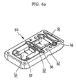
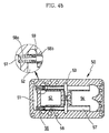
- Figs. 4a and 4b shows in detail the construction of the ejector plate-type cover 50 produced in the form of an ejector plate. In Figs.
- the reference numerals 51, 52, 53 and 54 denote a second air inlet chamber, a second vacuum chamber, a sub-vacuum chamber and a second air outlet chamber formed on the cover 50, respectively.
- the reference numerals 55, 56 and 57 respectively denote nozzle holes, allowing the chambers 51, 52, 53 and 54 to communicate with each other.
- the cover 50 preferably includes first and second nozzle spouts 58a and 58b which are set in two nozzle holes 55 and 56, respectively, such that the nozzle spouts 58a and 58b are coupled to each other in the vacuum chamber 52.
- a plurality of radial holes 59 are formed in the sidewall of the second nozzle spout 58b at positions around the coupled junction of the two spouts 58a and 58b.
- the ejector pump 60 created by both the ejector unit 25 and the ejector plate-type cover 50 according to the preferred embodiment, several chambers 61, 62 and 63 functioning as an air inlot chamber, a vacuum chamber, and an air outlet chamber have volumes larger than those of an ejector pump having a panel-type cover, as shown in Fig. 3. Due to the enlarged volumes of the chambers 61, 62 and 63, the ejector pump 60 creates a high level of vacuum.
- the chambers 26, 27 and 28 of the ejector unit 25 communicate with each other through the nozzle holes 55, 56 and 57 of the cover 50, so that the ejector unit 25 may be not formed with the nozzle holes 29 and 30 which are separately holed in the unit 25 to allow the chambers 26, 27 and 28 to communicate with each other.
- the two nozzle spouts 58a and 58b also preferably allow the pump 60 to more quickly create desired vacuum.
- the reference numeral 33 denotes a dust collecting filter that is set in the vacuum port 22, and the reference numeral 34 denotes a sound absorbing filter that is set in the outlet port 23.
- a filter cap 35 is preferably mounted to the side surface of the block body 20 so as to hold the two filters 33 and 34 in their positions inside the two ports 22 and 23 without allowing an undesired removal of the filters 33 and 34 from the block body 20.
- the vacuum port 22 and the outlet port 22 and 23 are formed in the filter cap 35, in place of the side surface of the block body 20.
- the reference numeral 36 denotes a cover which covers a part of another outlet port 23'.
- Two valve bores 37a and 37b are vertically formed on the upper surface of the block body 20 at two spaced positions, such that the bores 37a and 37b perpendicularly meet a main flow path 40 which is formed in the block body 20 while axially extending from the inlet port 21.
- the first bore 37a positioned at the left side of the body 20, communicates with the inlet chamber 26 of the ejector unit 25 via a first communication hole 42a which extends downward from the bottom of the first bore 37a to the inlet chamber 26.
- the second bore 37b positioned at the right side of the body 20, communicates with the vacuum port 22 of the block body 20 via a second communication hole 42b which extends downward from the bottom of the second bore 37b, as shown in Fig.
- compressed air introduced into the vacuum generating device 10 via the inlet port 21 may flow to the inlet chamber 26 of the ejector unit 25 and the vacuum port 22 through the first and second communication holes 42a and 42b, respectively.
- the two communication holes 42a and 42b thus respectively constitute compressed air supply paths for the inlet chamber 26 of the ejector unit 25 and the vacuum port 22.
- the flow of inlet compressed air inside the vacuum generating device 10 is controlled by an operation of the valve mechanism 70 such that the inlet compressed air selectively flows to only one of the inlet chamber 26 and the vacuum port 22.
- valve mechanism 70 controllably opens or closes the first and second communication holes 42 and 42b which respectively branch from the main flow path 40 to the inlet chamber 26 of the ejector unit 25 and the vacuum port 22.
- the reference numeral 38 denotes a control screw that is threaded into the block body 20 to allow a user to adjust the opening ratio of the second communication hole 42b to control the speed of releasing vacuum from the vacuum chamber 62, as desired.
- control valve mechanism 70 The construction and operation of the control valve mechanism 70 will be described herein below. However, it should be understood that the construction of the valve mechanism 70 may be altered without being limited to the following construction, if the alteration does not affect the functioning of the present invention.
- the control valve mechanism 70 comprises two ON/OFF control valves 71a and 71b that are set in the two valve bores 37a and 37b, respectively.
- the control valve mechanism 70 also includes the support plate 81 and two solenoid valves 82a and 82b.
- the support plate 81 is mounted to the top surface of the block body 20, such that the plate 81 receives the upper portions of the two ON/OFF control valves 71a and 71b.
- the former 82a functions as a vacuum-on solenoid valve
- the latter 82b functions as a vacuum-off solenoid valve.
- the two ON/OFF control valves 71a and 71b are pneumatic control valves that are pneumatically operated to change their state from a normal OFF-state to an ON-state.
- the two solenoid valves 82a and 82b are normally closed-type solenoid valves.
- each of the two ON/OFF control valves 71a and 71b comprises a cylindrical retainer 72 and a valve body 77 which may be assembled with each other into a single body.
- the retainer 72 is an integrated cylindrical body, which is hollowed along its central axis, with upper and lower end parts 73 and 74 having the same outer diameter, and an intermediate part 75 having an outer diameter smaller than that of the two end parts 73 and 74.
- An opening 76 is formed at a sidewall of the intermediate part 75.
- the valve body 77 is an integrated member, including a valve head 78 and a valve stem 79. The diameter of the valve head 78 is determined such that the head 78 is seated on the top end of the retainer 72.
- valve stem 79 integrally extends downward from the center of the valve head 78 such that the valve stem 79 movably and axially passes the central bore of the retainer 72.
- a rubber ring 80 is fitted over the lower end of the valve stem 79, and has a diameter capable of allowing the ring 80 to seal the lower end of the central bore of the retainer 72 in a normal state.
- the retainer 72 of each valve 71a, 71b is installed in an associated valve bore 37a, 37b such that the upper and lower end parts 73 and 74 are in close contact with the inner surface of the bore 37a, 37b while the valve body 77 is installed in the valve bore 37a, 37b such that it is linearly movable within a predetermined range in a vertical direction.
- the intermediate part 75 of each retainer 72 is positioned at the same level as the main flow path 40 extending horizontally from the inlet port 21. Therefore, the intermediate parts 75 of the retainers 72 do not block the main flow path 40.
- the two ON/OFF control valves 71a and 71b are pneumatic control valves that are pneumatically operated to change their state from a normal OFF-state to an ON-state.
- the main flow path 40 has two branch paths 41a and 41b that supply compressed air to the top surfaces of the valve heads 78 of the two ON/OFF control valves 71a and 71b, respectively.
- the two normally closed-type solenoid valves 82a and 82b are installed at positions where the solenoid valves 82a and 82b control the first and second branch paths 41a and 41b, respectively.
- the first branch path 41a primarily extends upwardly from the main flow path 40 in a vertical direction at a left side of the block body 20, upwardly passes the support plate 81, passes the vacuum-on solenoid valve 82a in an ON-state, and finally passes downwardly the support plate 81 until the path 41a communicates with the top surface of the valve head 78 of the fist ON/OFF control valve 71a.
- the second branch path 41b primarily extends upwardly from the main flow path 40 in a vertical direction at a right side of the block body 20, upwardly passes the support plate 81, passes the vacuum-off solenoid valve 82b in an ON-state, and finally passes downwardly the support plate 81 until the path 41b communicates with the top surface of the valve head 78 of the second ON/OFF control valve 71b. Since the two solenoid valves 82a and 82b are normally closed-type solenoid valves as described above, the two branch paths 41a and 41b are maintained at their closed states during a normal state of the two solenoid valves 82a and 82b.
- an absorption means (not shown) of a vacuum system is connected to the vacuum port 22 of the device 10, while an external compressed air source (not shown) is connected to the inlet port 21 of the device 10.
- an external compressed air source (not shown) is connected to the inlet port 21 of the device 10.
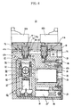
- valve body 77 of the first ON/OFF control valve 71a moves downward by a predetermined distance, so that a clearance C1 is created between the rubber ring 80 and the lower end of the central bore of the retainer 72 of the valve 71a, as shown in Fig. 6. Therefore, inlet compressed air in the main flow path 40 sequentially passes through the opening 76 formed at the sidewall of the intermediate part 75 of the retainer 72, the clearance C1, and the first communication hole 42a, thus being fed to the inlet chamber 61 of the ejector pump 60. The compressed air in the inlet chamber 61 sequentially flows through the nozzle holes 55, 56 and 57 to pass the vacuum chamber 62 and the outlet chamber 63, thus being discharged from the device 10 to the outside via the outlet port 23.
- air in the absorption means such as an absorption pad connected to the vacuum port 22 is sucked into the vacuum chamber 62 through the orifice 31, and is discharged from the device 10 to the outside along with the compressed air. Desired vacuum is thus created in the vacuum chamber 62, so that desired negative pressure is generated in the absorption means and allows the absorption means to take a target material, such as a workpiece.
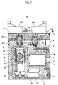
- inlet compressed air in the main flow path 40 sequentially passes through the opening 76 formed at the sidewall of the intermediate part 75 of the retainer 72, the clearance C2, and the second communication hole 42b, thus being fed to the vacuum port 22. Therefore, vacuum is quickly eliminated from the vacuum chamber 62, so that negative pressure is released from the absorption means.
- the vacuum generating device 10 of the present invention it is possible to adjust the vacuum releasing speed by appropriately tightening or loosening the control screw 38 relative to the body 20 such that the opening ratio of the second communication hole 42b is adjusted by the inside end of the control screw 38.
- the present invention provides a vacuum generating device preferably used in a variety of vacuum systems, such as a vacuum feeding system.
- an ejector unit is integrally formed in a block body by recessing a surface of the block body at a predetermined portion.
- a cover covers the ejector unit, thus preventing exposure of the ejector unit to the outside of the block body. Therefore, the vacuum generating device of this invention accomplishes the recent trend of compactness and smallness of such devices, effectively protects its ejector unit from damage, and does not increase its production cost in comparison with conventional vacuum generating devices.
Landscapes
- Engineering & Computer Science (AREA)
- Mechanical Engineering (AREA)
- General Engineering & Computer Science (AREA)
- Physics & Mathematics (AREA)
- Fluid Mechanics (AREA)
- Jet Pumps And Other Pumps (AREA)
Applications Claiming Priority (2)
| Application Number | Priority Date | Filing Date | Title |
|---|---|---|---|
| KR10-2001-0063300A KR100454082B1 (ko) | 2001-10-15 | 2001-10-15 | 진공 발생/파기 장치 |
| KR2001063300 | 2001-10-15 |
Publications (1)
| Publication Number | Publication Date |
|---|---|
| EP1302671A1 true EP1302671A1 (fr) | 2003-04-16 |
Family
ID=19715113
Family Applications (1)
| Application Number | Title | Priority Date | Filing Date |
|---|---|---|---|
| EP02257134A Withdrawn EP1302671A1 (fr) | 2001-10-15 | 2002-10-15 | Dispositif pour l'obtention d'un vide |
Country Status (4)
| Country | Link |
|---|---|
| US (1) | US6779985B2 (fr) |
| EP (1) | EP1302671A1 (fr) |
| KR (1) | KR100454082B1 (fr) |
| CN (1) | CN1412446A (fr) |
Cited By (3)
| Publication number | Priority date | Publication date | Assignee | Title |
|---|---|---|---|---|
| EP2125585A4 (fr) * | 2007-03-15 | 2012-11-14 | Korea Pneumatic Sys Co Ltd | Système de vide utilisant une cartouche de filtre |
| CN107725495A (zh) * | 2017-11-16 | 2018-02-23 | 苏州亚米拉机械有限公司 | 真空自动发生控制装置 |
| EP3152417A4 (fr) * | 2014-06-06 | 2018-05-23 | Dayco IP Holdings, LLC | Atténuation de bruit dans un dispositif venturi et/ou des clapets anti-retour |
Families Citing this family (10)
| Publication number | Priority date | Publication date | Assignee | Title |
|---|---|---|---|---|
| TWD105315S1 (zh) * | 2003-12-01 | 2005-06-21 | 股份有限公司 | 真空產生器 |
| TWD105140S1 (zh) * | 2003-12-01 | 2005-06-11 | 股份有限公司 | 真空用機器 |
| KR20040011571A (ko) * | 2004-01-09 | 2004-02-05 | 한국뉴매틱(주) | 진공 이젝터 장치 |
| DE102004031924B4 (de) * | 2004-06-23 | 2006-05-04 | J. Schmalz Gmbh | Vorrichtung zum Erzeugen eines Unterdrucks |
| KR100578540B1 (ko) * | 2004-07-28 | 2006-05-15 | 한국뉴매틱(주) | 진공 이젝터 펌프 |
| KR101306061B1 (ko) * | 2012-02-27 | 2013-09-17 | (주)쏠백 | 진공 발생기 |
| KR101304140B1 (ko) * | 2012-03-06 | 2013-09-05 | 이우승 | 진공 이젝터 펌프의 에어저감용 온오프밸브 |
| CN103016424B (zh) * | 2012-11-22 | 2015-09-30 | 温州阿尔贝斯气动有限公司 | 一种集成式真空发生器 |
| JP1525031S (fr) * | 2014-08-07 | 2015-06-01 | ||
| KR102225162B1 (ko) * | 2020-06-19 | 2021-03-09 | (주)브이텍 | 진공 시스템용 에어-밸브 유닛 |
Citations (3)
| Publication number | Priority date | Publication date | Assignee | Title |
|---|---|---|---|---|
| US4523894A (en) * | 1983-06-03 | 1985-06-18 | Svenska Rotor Maskiner Aktiebolag | Ejector pump with ringshaped nozzle |
| JPS614899A (ja) * | 1984-06-18 | 1986-01-10 | Shoketsu Kinzoku Kogyo Co Ltd | エゼクタ装置 |
| EP0346314A2 (fr) * | 1988-06-08 | 1989-12-13 | Peter Tell | Dispositif à éjecteur à vide |
Family Cites Families (11)
| Publication number | Priority date | Publication date | Assignee | Title |
|---|---|---|---|---|
| JPS619599U (ja) | 1984-06-20 | 1986-01-21 | 株式会社 妙徳 | エゼクタポンプ |
| IL74282A0 (en) * | 1985-02-08 | 1985-05-31 | Dan Greenberg | Multishaft jet suction device |
| JPH0545904Y2 (fr) | 1987-05-30 | 1993-11-29 | ||
| US4880358A (en) | 1988-06-20 | 1989-11-14 | Air-Vac Engineering Company, Inc. | Ultra-high vacuum force, low air consumption pumps |
| US5683227A (en) | 1993-03-31 | 1997-11-04 | Smc Corporation | Multistage ejector assembly |
| SE510780C2 (sv) * | 1996-07-22 | 1999-06-21 | Mecman Ab Rexroth | Anordning för alstring av undertryck samt ramparrangemang med en dylik anordning |
| DE19732056A1 (de) | 1997-07-25 | 1999-01-28 | Schuler Pressen Gmbh & Co | Vakuumsystem für ein Transfersystem |
| JPH11114862A (ja) | 1997-10-20 | 1999-04-27 | Smc Corp | 真空発生用ユニット |
| DE19817249C1 (de) | 1998-04-18 | 1999-08-26 | Schmalz J Gmbh | Ejektor |
| IL125791A (en) | 1998-08-13 | 2004-05-12 | Dan Greenberg | Vacuum pump |
| JP3678950B2 (ja) | 1999-09-03 | 2005-08-03 | Smc株式会社 | 真空発生用ユニット |
-
2001
- 2001-10-15 KR KR10-2001-0063300A patent/KR100454082B1/ko not_active Expired - Fee Related
-
2002
- 2002-10-15 EP EP02257134A patent/EP1302671A1/fr not_active Withdrawn
- 2002-10-15 CN CN02146244A patent/CN1412446A/zh active Pending
- 2002-10-15 US US10/271,637 patent/US6779985B2/en not_active Expired - Fee Related
Patent Citations (3)
| Publication number | Priority date | Publication date | Assignee | Title |
|---|---|---|---|---|
| US4523894A (en) * | 1983-06-03 | 1985-06-18 | Svenska Rotor Maskiner Aktiebolag | Ejector pump with ringshaped nozzle |
| JPS614899A (ja) * | 1984-06-18 | 1986-01-10 | Shoketsu Kinzoku Kogyo Co Ltd | エゼクタ装置 |
| EP0346314A2 (fr) * | 1988-06-08 | 1989-12-13 | Peter Tell | Dispositif à éjecteur à vide |
Non-Patent Citations (1)
| Title |
|---|
| PATENT ABSTRACTS OF JAPAN vol. 010, no. 151 (M - 483) 31 May 1986 (1986-05-31) * |
Cited By (4)
| Publication number | Priority date | Publication date | Assignee | Title |
|---|---|---|---|---|
| EP2125585A4 (fr) * | 2007-03-15 | 2012-11-14 | Korea Pneumatic Sys Co Ltd | Système de vide utilisant une cartouche de filtre |
| EP3152417A4 (fr) * | 2014-06-06 | 2018-05-23 | Dayco IP Holdings, LLC | Atténuation de bruit dans un dispositif venturi et/ou des clapets anti-retour |
| US10519984B2 (en) | 2014-06-06 | 2019-12-31 | Dayco Ip Holdings, Llc | Noise attenuation in a Venturi device and/or check valves |
| CN107725495A (zh) * | 2017-11-16 | 2018-02-23 | 苏州亚米拉机械有限公司 | 真空自动发生控制装置 |
Also Published As
| Publication number | Publication date |
|---|---|
| US20030072653A1 (en) | 2003-04-17 |
| US6779985B2 (en) | 2004-08-24 |
| KR100454082B1 (ko) | 2004-10-26 |
| CN1412446A (zh) | 2003-04-23 |
| KR20030031592A (ko) | 2003-04-23 |
Similar Documents
| Publication | Publication Date | Title |
|---|---|---|
| US6779985B2 (en) | Vacuum generating device | |
| CN100510486C (zh) | 控制式二通阀 | |
| US5683227A (en) | Multistage ejector assembly | |
| US6109291A (en) | Pilot 5-port transfer valve | |
| US20050178443A1 (en) | Relief valve | |
| KR102525827B1 (ko) | 세로형 진공 그리퍼 장치 | |
| US20050118032A1 (en) | Vaccum-generating unit | |
| US11959500B2 (en) | Air cylinder, head cover, and rod cover | |
| CN101566855A (zh) | 用在流体压力装置中的节流结构 | |
| KR100244540B1 (ko) | 베이스부착형 전환밸브에 부착하기 위한 압력조절밸브 | |
| US7159610B2 (en) | Relief valve | |
| KR20040011571A (ko) | 진공 이젝터 장치 | |
| EP0911559B1 (fr) | Valve de commande directionnelle pilotée | |
| JP2006342765A (ja) | 真空ユニット及び真空ユニットに用いられるフィルタの製造方法 | |
| JPH0788911B2 (ja) | 一体流量制御装置付き弁ベース | |
| US7040742B2 (en) | Ink flow control device for ink jet type printer | |
| JPH11311349A (ja) | 水圧リリーフ弁 | |
| US20220205467A1 (en) | High-pressure fluid discharge device | |
| CN114729709A (zh) | 脉冲阀 | |
| US6427578B1 (en) | Rodless cylinder | |
| JP2002338110A (ja) | 吹き付け空気の制御装置 | |
| JP2605802Y2 (ja) | スピードコントローラ | |
| JP3634412B2 (ja) | 流体制御装置 | |
| KR200370181Y1 (ko) | 진공파괴용 체적이 구비된 진공발생유니트 | |
| CN100532866C (zh) | 双手操作用控制阀 |
Legal Events
| Date | Code | Title | Description |
|---|---|---|---|
| PUAI | Public reference made under article 153(3) epc to a published international application that has entered the european phase |
Free format text: ORIGINAL CODE: 0009012 |
|
| AK | Designated contracting states |
Designated state(s): AT BE BG CH CY CZ DE DK EE ES FI FR GB GR IE IT LI LU MC NL PT SE SK TR |
|
| AX | Request for extension of the european patent |
Extension state: AL LT LV MK RO SI |
|
| 17P | Request for examination filed |
Effective date: 20031014 |
|
| AKX | Designation fees paid |
Designated state(s): AT BE BG CH CY CZ DE DK EE ES FI FR GB GR IE IT LI LU MC NL PT SE SK TR |
|
| 17Q | First examination report despatched |
Effective date: 20031222 |
|
| STAA | Information on the status of an ep patent application or granted ep patent |
Free format text: STATUS: THE APPLICATION IS DEEMED TO BE WITHDRAWN |
|
| 18D | Application deemed to be withdrawn |
Effective date: 20040702 |