EP1302706A2 - Boíte de vitesses - Google Patents
Boíte de vitesses Download PDFInfo
- Publication number
- EP1302706A2 EP1302706A2 EP02019950A EP02019950A EP1302706A2 EP 1302706 A2 EP1302706 A2 EP 1302706A2 EP 02019950 A EP02019950 A EP 02019950A EP 02019950 A EP02019950 A EP 02019950A EP 1302706 A2 EP1302706 A2 EP 1302706A2
- Authority
- EP
- European Patent Office
- Prior art keywords
- manual transmission
- transmission according
- shift
- switching
- actuating devices
- Prior art date
- Legal status (The legal status is an assumption and is not a legal conclusion. Google has not performed a legal analysis and makes no representation as to the accuracy of the status listed.)
- Granted
Links
Images


Classifications
-
- F—MECHANICAL ENGINEERING; LIGHTING; HEATING; WEAPONS; BLASTING
- F16—ENGINEERING ELEMENTS AND UNITS; GENERAL MEASURES FOR PRODUCING AND MAINTAINING EFFECTIVE FUNCTIONING OF MACHINES OR INSTALLATIONS; THERMAL INSULATION IN GENERAL
- F16H—GEARING
- F16H61/00—Control functions within control units of change-speed- or reversing-gearings for conveying rotary motion ; Control of exclusively fluid gearing, friction gearing, gearings with endless flexible members or other particular types of gearing
- F16H61/26—Generation or transmission of movements for final actuating mechanisms
- F16H61/28—Generation or transmission of movements for final actuating mechanisms with at least one movement of the final actuating mechanism being caused by a non-mechanical force, e.g. power-assisted
- F16H61/32—Electric motors , actuators or related electrical control means therefor
-
- F—MECHANICAL ENGINEERING; LIGHTING; HEATING; WEAPONS; BLASTING
- F16—ENGINEERING ELEMENTS AND UNITS; GENERAL MEASURES FOR PRODUCING AND MAINTAINING EFFECTIVE FUNCTIONING OF MACHINES OR INSTALLATIONS; THERMAL INSULATION IN GENERAL
- F16H—GEARING
- F16H63/00—Control outputs from the control unit to change-speed- or reversing-gearings for conveying rotary motion or to other devices than the final output mechanism
- F16H63/02—Final output mechanisms therefor; Actuating means for the final output mechanisms
- F16H63/28—Final output mechanisms therefor; Actuating means for the final output mechanisms two or more final actuating mechanisms moving the same final output mechanism
- F16H63/285—Final output mechanisms therefor; Actuating means for the final output mechanisms two or more final actuating mechanisms moving the same final output mechanism with a first final actuating member applying a force to two or more final output members and a second final actuating member locking in position another final output member
-
- F—MECHANICAL ENGINEERING; LIGHTING; HEATING; WEAPONS; BLASTING
- F16—ENGINEERING ELEMENTS AND UNITS; GENERAL MEASURES FOR PRODUCING AND MAINTAINING EFFECTIVE FUNCTIONING OF MACHINES OR INSTALLATIONS; THERMAL INSULATION IN GENERAL
- F16H—GEARING
- F16H63/00—Control outputs from the control unit to change-speed- or reversing-gearings for conveying rotary motion or to other devices than the final output mechanism
- F16H63/02—Final output mechanisms therefor; Actuating means for the final output mechanisms
- F16H63/30—Constructional features of the final output mechanisms
- F16H63/3023—Constructional features of the final output mechanisms the final output mechanisms comprising elements moved by fluid pressure
-
- F—MECHANICAL ENGINEERING; LIGHTING; HEATING; WEAPONS; BLASTING
- F16—ENGINEERING ELEMENTS AND UNITS; GENERAL MEASURES FOR PRODUCING AND MAINTAINING EFFECTIVE FUNCTIONING OF MACHINES OR INSTALLATIONS; THERMAL INSULATION IN GENERAL
- F16H—GEARING
- F16H63/00—Control outputs from the control unit to change-speed- or reversing-gearings for conveying rotary motion or to other devices than the final output mechanism
- F16H63/02—Final output mechanisms therefor; Actuating means for the final output mechanisms
- F16H63/30—Constructional features of the final output mechanisms
- F16H63/304—Constructional features of the final output mechanisms the final output mechanisms comprising elements moved by electrical or magnetic force
- F16H2063/305—Constructional features of the final output mechanisms the final output mechanisms comprising elements moved by electrical or magnetic force using electromagnetic solenoids
-
- F—MECHANICAL ENGINEERING; LIGHTING; HEATING; WEAPONS; BLASTING
- F16—ENGINEERING ELEMENTS AND UNITS; GENERAL MEASURES FOR PRODUCING AND MAINTAINING EFFECTIVE FUNCTIONING OF MACHINES OR INSTALLATIONS; THERMAL INSULATION IN GENERAL
- F16H—GEARING
- F16H63/00—Control outputs from the control unit to change-speed- or reversing-gearings for conveying rotary motion or to other devices than the final output mechanism
- F16H63/02—Final output mechanisms therefor; Actuating means for the final output mechanisms
- F16H63/30—Constructional features of the final output mechanisms
- F16H2063/3079—Shift rod assembly, e.g. supporting, assembly or manufacturing of shift rails or rods; Special details thereof
-
- F—MECHANICAL ENGINEERING; LIGHTING; HEATING; WEAPONS; BLASTING
- F16—ENGINEERING ELEMENTS AND UNITS; GENERAL MEASURES FOR PRODUCING AND MAINTAINING EFFECTIVE FUNCTIONING OF MACHINES OR INSTALLATIONS; THERMAL INSULATION IN GENERAL
- F16H—GEARING
- F16H63/00—Control outputs from the control unit to change-speed- or reversing-gearings for conveying rotary motion or to other devices than the final output mechanism
- F16H63/02—Final output mechanisms therefor; Actuating means for the final output mechanisms
- F16H63/30—Constructional features of the final output mechanisms
- F16H63/32—Gear shift yokes, e.g. shift forks
- F16H2063/321—Gear shift yokes, e.g. shift forks characterised by the interface between fork body and shift rod, e.g. fixing means, bushes, cams or pins
-
- F—MECHANICAL ENGINEERING; LIGHTING; HEATING; WEAPONS; BLASTING
- F16—ENGINEERING ELEMENTS AND UNITS; GENERAL MEASURES FOR PRODUCING AND MAINTAINING EFFECTIVE FUNCTIONING OF MACHINES OR INSTALLATIONS; THERMAL INSULATION IN GENERAL
- F16H—GEARING
- F16H63/00—Control outputs from the control unit to change-speed- or reversing-gearings for conveying rotary motion or to other devices than the final output mechanism
- F16H63/02—Final output mechanisms therefor; Actuating means for the final output mechanisms
- F16H63/30—Constructional features of the final output mechanisms
- F16H63/32—Gear shift yokes, e.g. shift forks
- F16H2063/325—Rocker or swiveling forks, i.e. the forks are pivoted in the gear case when moving the sleeve
-
- F—MECHANICAL ENGINEERING; LIGHTING; HEATING; WEAPONS; BLASTING
- F16—ENGINEERING ELEMENTS AND UNITS; GENERAL MEASURES FOR PRODUCING AND MAINTAINING EFFECTIVE FUNCTIONING OF MACHINES OR INSTALLATIONS; THERMAL INSULATION IN GENERAL
- F16H—GEARING
- F16H63/00—Control outputs from the control unit to change-speed- or reversing-gearings for conveying rotary motion or to other devices than the final output mechanism
- F16H63/02—Final output mechanisms therefor; Actuating means for the final output mechanisms
- F16H63/30—Constructional features of the final output mechanisms
- F16H63/3013—Constructional features of the final output mechanisms the final output mechanism being characterised by linkages converting movement, e.g. into opposite direction by a pivoting lever linking two shift rods
-
- Y—GENERAL TAGGING OF NEW TECHNOLOGICAL DEVELOPMENTS; GENERAL TAGGING OF CROSS-SECTIONAL TECHNOLOGIES SPANNING OVER SEVERAL SECTIONS OF THE IPC; TECHNICAL SUBJECTS COVERED BY FORMER USPC CROSS-REFERENCE ART COLLECTIONS [XRACs] AND DIGESTS
- Y10—TECHNICAL SUBJECTS COVERED BY FORMER USPC
- Y10T—TECHNICAL SUBJECTS COVERED BY FORMER US CLASSIFICATION
- Y10T74/00—Machine element or mechanism
- Y10T74/19—Gearing
- Y10T74/19219—Interchangeably locked
- Y10T74/19251—Control mechanism
-
- Y—GENERAL TAGGING OF NEW TECHNOLOGICAL DEVELOPMENTS; GENERAL TAGGING OF CROSS-SECTIONAL TECHNOLOGIES SPANNING OVER SEVERAL SECTIONS OF THE IPC; TECHNICAL SUBJECTS COVERED BY FORMER USPC CROSS-REFERENCE ART COLLECTIONS [XRACs] AND DIGESTS
- Y10—TECHNICAL SUBJECTS COVERED BY FORMER USPC
- Y10T—TECHNICAL SUBJECTS COVERED BY FORMER US CLASSIFICATION
- Y10T74/00—Machine element or mechanism
- Y10T74/20—Control lever and linkage systems
- Y10T74/20012—Multiple controlled elements
- Y10T74/20018—Transmission control
- Y10T74/20085—Restriction of shift, gear selection, or gear engagement
-
- Y—GENERAL TAGGING OF NEW TECHNOLOGICAL DEVELOPMENTS; GENERAL TAGGING OF CROSS-SECTIONAL TECHNOLOGIES SPANNING OVER SEVERAL SECTIONS OF THE IPC; TECHNICAL SUBJECTS COVERED BY FORMER USPC CROSS-REFERENCE ART COLLECTIONS [XRACs] AND DIGESTS
- Y10—TECHNICAL SUBJECTS COVERED BY FORMER USPC
- Y10T—TECHNICAL SUBJECTS COVERED BY FORMER US CLASSIFICATION
- Y10T74/00—Machine element or mechanism
- Y10T74/20—Control lever and linkage systems
- Y10T74/20012—Multiple controlled elements
- Y10T74/20018—Transmission control
- Y10T74/20177—Particular element [e.g., shift fork, template, etc.]
- Y10T74/20183—Shift fork structure
Definitions
- the present invention relates to a manual transmission according to the preamble of claim 1.
- a pin assigned to the shift fork slides into a recess in the Shift rod and provides a positive connection between the Shift fork and the shift rod.
- the shift rod becomes axial shifted, so the respective shift fork and the assigned Shift sleeve taken away. So the electromagnetic actuators form an "inner circuit" of the transmission.
- the object of the invention is to provide a manual transmission with extended "degrees of freedom" to accomplish.
- the basic principle of the invention consists in a manual transmission in which individual switch bodies, i.e. Shift forks and swing arms, respectively two separate actuators are assigned.
- a switch body i.e. a shift fork or a shift rocker, can optionally by the one or the other actuating device are actuated.
- the Actuators are preferably shift rods.
- the shift rods run essentially parallel to each other Recesses of the switch body.
- On the individual switch bodies are each two e.g. assigned to the two shift rods electromagnetic or mechanically actuated actuators are provided. By pressing the Actuators can be a coupling between the shift rod and the Switch body are manufactured.
- a major advantage of the invention compared to the above State of the art is that two coaxially arranged switching bodies can be switched simultaneously, especially in different ones Switching directions.
- the switching elements are with the electromagnetic actuators Shift rods can be coupled. That is, they are in the uncoupled state Shift rods displaceable relative to the switch bodies.
- the invention provides that the switching body not only in one very specific relative position can be coupled with a shift rod, but that there are several "slide positions" of the shift rod in which a coupling of the shift rod with the switch body is possible.
- the shift rod can be provided in the shift rod several recesses in the an associated actuator of the switch body can intervene.
- a shift fork or rocker arm usually has a neutral position and two switch positions. In this case, the shift rod in the Area of the switching body have three recesses.
- the shift rods can preferably be actuated independently of one another. But it can also be provided that the shift rods at the same time but can only be operated in different "shooting directions”.
- the shift rods are by a mechanical coupling element coupled together. Through the they can be coupled mechanically by means of a single actuator, e.g. a single hydraulic cylinder or one electric servomotor, operated in opposite directions.
- the coupling element can, for example, a rocker arm mounted in the gearbox or a Be gear, that with rack sections of the two shift rods combs.
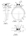
- Figures 1 to 3 show a sliding sleeve 1, which is non-rotatably but axially displaceably arranged on a fixed sleeve 2 of a gear shaft.
- a circumferential groove 3 is provided on the outer circumference of the sliding sleeve 1, into which a shift fork 4 engages in a form-fitting manner.
- the shift fork 4 has two through bores 5, 6, through which shift rods 7, 8 extend. The shift rods 7, 8 are therefore relatively displaceable with respect to the shift fork 4.
- the electromagnetic actuators 9, 10 each have a coupling pin biased by a compression spring into a "neutral position" 11 on, as well as an electromagnet, for moving the coupling pin 11 against the spring force.
- Three recesses 12-14 are provided on the shift rods 7, 8.
- the coupling pins 11 can "engage” one of the recesses 12-14 are brought. This allows the shift rods 7 and 8 with the shift fork 4 or the sliding sleeve 1 are coupled.
- the Sliding sleeve 1 can thus by actuating the actuators 9 and 10 respectively the shift rods 7 and 8 are axially displaced.
- shift fork 4 has two separate "actuators", i.e. two shift rods 7, 8 are assigned.
- the shift fork 4 can switched both via the shift rod 7 and via the shift rod 8 become.
- the two shift rods 7, 8 can either be completely independent of one another be controllable or mechanically coupled, which is related is explained in more detail with FIGS. 5-8.
- FIG. 4 shows an embodiment in which the sliding sleeve 1 is axially displaceable by means of a U-shaped rocker arm 15.
- the rocker arm 15 is pivotally mounted about an axis 16 in the transmission.
- sliding blocks 17, 18 are provided which engage in the circumferential groove 3 (see FIG. 1) and take the sliding sleeve in the axial direction when pivoting the rocker arm 15.
- a driver finger 19 is provided which is axially displaceable by a shift rod guide 20, which leads to the pivoting of the rocker arm 15.
- the shift rod guide has two through bores 5, 6 through which the two shift rods 7, 8 extend.
- electromagnetic actuators 9, 10 are provided which enable a form-locking coupling of the shift rod guide with one of the two shift rods 7, 8.
- FIGS. 5-8 show exemplary embodiments of the invention in which the shift rods 7, 8 are each mechanically coupled to one another via a coupling element.
- the coupling element is a T-shaped lever 21 which is pivotally mounted on a bearing 22 in the transmission and which is coupled to the shift rods 7, 8 via joints 23, 24 and to an actuator 26 via a joint 25.
- the actuator 26 can be, for example, a hydraulic or pneumatic cylinder or an electric motor.
- both shift rods can be axially displaced become. Since the bearing point 22 of the lever 21 between the two Shift rods 7, 8, they are each in different directions postponed.
- FIG. 6 shows a variant of FIG. 5 with a rod-like lever which is likewise mounted on a bearing 21 in the transmission and is coupled to the shift rods 7, 8 via joints 23, 24 and to the actuator 26 via a joint 25.
- Figure 7 shows an embodiment in which the actuator 26 is connected directly to the shift rod 8. An axial movement of the shift rod 8 is converted via the rod-like lever 21 into an opposite axial movement of the shift rod 7.
- the "coupling element" of the two shift rods 7, 8 is a gear 27 which meshes with rack sections 28, 29 of the shift rods 7, 8.
- An axial movement introduced into the shift rod 8 via the actuator 26 is converted via the gear wheel 27 into an opposite axial movement of the shift rod 7.
Landscapes
- Engineering & Computer Science (AREA)
- General Engineering & Computer Science (AREA)
- Mechanical Engineering (AREA)
- Physics & Mathematics (AREA)
- Fluid Mechanics (AREA)
- Gear-Shifting Mechanisms (AREA)
Applications Claiming Priority (2)
| Application Number | Priority Date | Filing Date | Title |
|---|---|---|---|
| DE10150054A DE10150054A1 (de) | 2001-10-10 | 2001-10-10 | Schaltgetriebe |
| DE10150054 | 2001-10-10 |
Publications (3)
| Publication Number | Publication Date |
|---|---|
| EP1302706A2 true EP1302706A2 (fr) | 2003-04-16 |
| EP1302706A3 EP1302706A3 (fr) | 2004-07-28 |
| EP1302706B1 EP1302706B1 (fr) | 2005-06-29 |
Family
ID=7702089
Family Applications (1)
| Application Number | Title | Priority Date | Filing Date |
|---|---|---|---|
| EP02019950A Expired - Lifetime EP1302706B1 (fr) | 2001-10-10 | 2002-09-05 | Boíte de vitesses |
Country Status (4)
| Country | Link |
|---|---|
| US (1) | US6823755B2 (fr) |
| EP (1) | EP1302706B1 (fr) |
| JP (1) | JP2003120807A (fr) |
| DE (2) | DE10150054A1 (fr) |
Cited By (3)
| Publication number | Priority date | Publication date | Assignee | Title |
|---|---|---|---|---|
| WO2007057197A1 (fr) * | 2005-11-19 | 2007-05-24 | Zf Friedrichshafen Ag | Transmission automatique et embrayage automatique a friction |
| WO2017153032A1 (fr) * | 2016-03-05 | 2017-09-14 | Wabco Gmbh | Boîte de vitesses automatique |
| WO2019200260A1 (fr) * | 2018-04-13 | 2019-10-17 | Dana Heavy Vehicle Systems Group, Llc | Ensemble d'actionnement de fourchette de changement de vitesses |
Families Citing this family (4)
| Publication number | Priority date | Publication date | Assignee | Title |
|---|---|---|---|---|
| DE10347491A1 (de) * | 2003-10-13 | 2005-05-19 | Zf Friedrichshafen Ag | Schalteinrichtung |
| US9383008B2 (en) * | 2013-02-01 | 2016-07-05 | Dana Automotive Systems Group, Llc | Gear shift mechanism |
| KR101543169B1 (ko) * | 2014-08-01 | 2015-08-13 | 현대자동차주식회사 | 이중 시프트 포크 구조 |
| KR101637693B1 (ko) * | 2014-10-15 | 2016-07-08 | 현대자동차주식회사 | 수동변속기용 변속 장치 |
Citations (1)
| Publication number | Priority date | Publication date | Assignee | Title |
|---|---|---|---|---|
| DE19920064C2 (de) | 1999-05-03 | 2001-04-12 | Daimler Chrysler Ag | Zahnräderwechselgetriebe für ein Kraftfahrzeug |
Family Cites Families (20)
| Publication number | Priority date | Publication date | Assignee | Title |
|---|---|---|---|---|
| US1928782A (en) * | 1931-06-12 | 1933-10-03 | White Motor Co | Transmission |
| US2893256A (en) * | 1955-09-12 | 1959-07-07 | Stewart Warner Corp | Actuator for a two-speed adapter |
| US3495473A (en) * | 1968-03-25 | 1970-02-17 | Mack Trucks | Vehicle transmission shifting apparatus |
| US4449416A (en) * | 1981-09-04 | 1984-05-22 | J. I. Case Company | Transmission control system |
| JPS5967123A (ja) * | 1982-10-05 | 1984-04-16 | Aisin Seiki Co Ltd | 四輪駆動用トランスフア |
| JPS60128519A (ja) * | 1983-12-16 | 1985-07-09 | Aisin Seiki Co Ltd | 変速機の操作機構 |
| JPS60175847A (ja) * | 1984-02-22 | 1985-09-10 | Aisin Warner Ltd | パーキング機構付変速機 |
| JPS61160652A (ja) * | 1984-12-31 | 1986-07-21 | Hino Motors Ltd | トランスミツシヨンの変速操作装置 |
| US5205179A (en) * | 1990-07-21 | 1993-04-27 | Ina Walzlager Schaeffler Kg | Speed changing device |
| DE4335754A1 (de) * | 1993-10-20 | 1995-04-27 | Zahnradfabrik Friedrichshafen | Schaltvorrichtung mit Steuergliedern |
| DE19524116C2 (de) * | 1995-07-03 | 1999-07-15 | Ford Werke Ag | Schaltvorrichtung für ein halbautomatisch schaltbares Wechselgetriebe eines Kraftfahrzeuges |
| US5868644A (en) * | 1997-12-17 | 1999-02-09 | Ford Global Technologies, Inc. | Multiple speed powershift transmission providing synchronous speed ratio changes |
| FR2778444B1 (fr) * | 1998-05-05 | 2000-06-23 | Renault | Boite de vitesses compacte |
| JP3170257B2 (ja) * | 1999-02-22 | 2001-05-28 | 本田技研工業株式会社 | 変速機のギヤシフト機構 |
| DE19919270B4 (de) * | 1999-04-28 | 2009-01-15 | Schaeffler Kg | Schaltschwinge mit einem Bügel zur Krafteinleitung |
| DE19919271B4 (de) * | 1999-04-28 | 2009-04-30 | Schaeffler Kg | Schaltschwinge für ein Zahnräderwechselgetriebe |
| KR100302810B1 (ko) * | 1999-06-30 | 2001-09-22 | 이계안 | 차량용 전자 공압식 변속기의 변속 제어 방법 |
| JP2001065689A (ja) * | 1999-09-01 | 2001-03-16 | Aisin Ai Co Ltd | 変速機のコントロール装置 |
| DE10009505A1 (de) * | 2000-02-29 | 2001-08-30 | Hydraulik Ring Gmbh | Steuereinrichtung für automatisierte Schaltgetriebe von Fahrzeugen, vorzugsweise von Kraftfahrzeugen |
| DE10235404A1 (de) * | 2002-08-02 | 2004-02-12 | Bayerische Motoren Werke Ag | Schaltgetriebe mit einem Schaltkörper zum zeitgleichen Verschieben zweier Schaltmuffen |
-
2001
- 2001-10-10 DE DE10150054A patent/DE10150054A1/de not_active Withdrawn
-
2002
- 2002-09-05 DE DE50203488T patent/DE50203488D1/de not_active Expired - Lifetime
- 2002-09-05 EP EP02019950A patent/EP1302706B1/fr not_active Expired - Lifetime
- 2002-10-08 US US10/265,615 patent/US6823755B2/en not_active Expired - Fee Related
- 2002-10-10 JP JP2002297519A patent/JP2003120807A/ja active Pending
Patent Citations (1)
| Publication number | Priority date | Publication date | Assignee | Title |
|---|---|---|---|---|
| DE19920064C2 (de) | 1999-05-03 | 2001-04-12 | Daimler Chrysler Ag | Zahnräderwechselgetriebe für ein Kraftfahrzeug |
Cited By (4)
| Publication number | Priority date | Publication date | Assignee | Title |
|---|---|---|---|---|
| WO2007057197A1 (fr) * | 2005-11-19 | 2007-05-24 | Zf Friedrichshafen Ag | Transmission automatique et embrayage automatique a friction |
| WO2017153032A1 (fr) * | 2016-03-05 | 2017-09-14 | Wabco Gmbh | Boîte de vitesses automatique |
| WO2019200260A1 (fr) * | 2018-04-13 | 2019-10-17 | Dana Heavy Vehicle Systems Group, Llc | Ensemble d'actionnement de fourchette de changement de vitesses |
| US11391370B2 (en) | 2018-04-13 | 2022-07-19 | Dana Heavy Vehicle Systems Group, Llc | Shift fork actuation assembly |
Also Published As
| Publication number | Publication date |
|---|---|
| EP1302706A3 (fr) | 2004-07-28 |
| EP1302706B1 (fr) | 2005-06-29 |
| US20030066368A1 (en) | 2003-04-10 |
| US6823755B2 (en) | 2004-11-30 |
| DE50203488D1 (de) | 2005-08-04 |
| JP2003120807A (ja) | 2003-04-23 |
| DE10150054A1 (de) | 2003-04-17 |
Similar Documents
| Publication | Publication Date | Title |
|---|---|---|
| EP1521928B1 (fr) | Dispositif de changement de vitesses | |
| DE19635866C2 (de) | Schaltvorrichtung für ein Zahnräderwechselgetriebe | |
| EP1836421B1 (fr) | Dispositif d'actionnement de fourchettes | |
| EP0476005B1 (fr) | Dispositif de changement de vitesses pour la boite de vitesses de vehicules a moteur | |
| EP1302706B1 (fr) | Boíte de vitesses | |
| DE19823767A1 (de) | Vorrichtung zum Betätigen einer Schaltwelle eines Schaltgetriebes | |
| WO2018055041A2 (fr) | Actionneur de rapport et de voie (xy) de boîte de vitesses | |
| DE4017957A1 (de) | Schalteinrichtung eines kraftfahrzeuggetriebe | |
| EP1291560B1 (fr) | Dispositif de changement de rapports à commande assistée | |
| DE102012003482A1 (de) | Schaltvorrichtung für ein Antriebssystem für allradgetriebene Kraftfahrzeuge | |
| DE10151467A1 (de) | Schaltgetriebe mit Verriegelungseinrichtung zur Verriegelung einzelner Gänge | |
| EP1917462B1 (fr) | Dispositif de commutation pour deplacer une fourchette d'embrayage | |
| EP1711727B1 (fr) | Systeme de changement de vitesses | |
| DE10231609A1 (de) | Getriebeschaltung | |
| DE102013224063A1 (de) | Betätigungsvorrichtung für ein Kraftfahrzeuggetriebe | |
| DE19626178C2 (de) | Stelleinrichtung zur Betätigung eines Stellorgans | |
| DE10206470A1 (de) | Schaltgetriebe | |
| DE2206671C2 (de) | Mechanische Schalteinrichtung für ein Zahnradgetriebe mit Durchwahl | |
| DE69402162T2 (de) | Vorrichtung zur Steuerung eines Kraftfahrzeuggetriebes | |
| DE19929564A1 (de) | Umschaltgetriebe für Verstelleinrichtungen in Kraftfahrzeugen | |
| DE19939930A1 (de) | Miniaturgreifvorrichtung | |
| DE1480679C3 (de) | Schalteinrichtung für Geschwindigkeitswechselgetriebe von Kraftfahrzeugen | |
| DE10235404A1 (de) | Schaltgetriebe mit einem Schaltkörper zum zeitgleichen Verschieben zweier Schaltmuffen | |
| DE1936316A1 (de) | Druckmittelbetaetigter Stellkreis | |
| DE29923481U1 (de) | Anordnung mit Stellungsendschaltern für Motorantriebe |
Legal Events
| Date | Code | Title | Description |
|---|---|---|---|
| PUAI | Public reference made under article 153(3) epc to a published international application that has entered the european phase |
Free format text: ORIGINAL CODE: 0009012 |
|
| AK | Designated contracting states |
Designated state(s): AT BE BG CH CY CZ DE DK EE ES FI FR GB GR IE IT LI LU MC NL PT SE SK TR |
|
| AX | Request for extension of the european patent |
Extension state: AL LT LV MK RO SI |
|
| PUAL | Search report despatched |
Free format text: ORIGINAL CODE: 0009013 |
|
| AK | Designated contracting states |
Kind code of ref document: A3 Designated state(s): AT BE BG CH CY CZ DE DK EE ES FI FR GB GR IE IT LI LU MC NL PT SE SK TR |
|
| AX | Request for extension of the european patent |
Extension state: AL LT LV MK RO SI |
|
| 17P | Request for examination filed |
Effective date: 20040623 |
|
| 17Q | First examination report despatched |
Effective date: 20041011 |
|
| GRAP | Despatch of communication of intention to grant a patent |
Free format text: ORIGINAL CODE: EPIDOSNIGR1 |
|
| AKX | Designation fees paid |
Designated state(s): DE FR GB IT |
|
| GRAS | Grant fee paid |
Free format text: ORIGINAL CODE: EPIDOSNIGR3 |
|
| GRAA | (expected) grant |
Free format text: ORIGINAL CODE: 0009210 |
|
| AK | Designated contracting states |
Kind code of ref document: B1 Designated state(s): DE FR GB IT |
|
| REG | Reference to a national code |
Ref country code: GB Ref legal event code: FG4D Free format text: NOT ENGLISH |
|
| GBT | Gb: translation of ep patent filed (gb section 77(6)(a)/1977) |
Effective date: 20050629 |
|
| REF | Corresponds to: |
Ref document number: 50203488 Country of ref document: DE Date of ref document: 20050804 Kind code of ref document: P |
|
| ET | Fr: translation filed | ||
| PLBE | No opposition filed within time limit |
Free format text: ORIGINAL CODE: 0009261 |
|
| STAA | Information on the status of an ep patent application or granted ep patent |
Free format text: STATUS: NO OPPOSITION FILED WITHIN TIME LIMIT |
|
| 26N | No opposition filed |
Effective date: 20060330 |
|
| PGFP | Annual fee paid to national office [announced via postgrant information from national office to epo] |
Ref country code: DE Payment date: 20130913 Year of fee payment: 12 |
|
| PGFP | Annual fee paid to national office [announced via postgrant information from national office to epo] |
Ref country code: GB Payment date: 20130926 Year of fee payment: 12 |
|
| PGFP | Annual fee paid to national office [announced via postgrant information from national office to epo] |
Ref country code: IT Payment date: 20130927 Year of fee payment: 12 |
|
| PGFP | Annual fee paid to national office [announced via postgrant information from national office to epo] |
Ref country code: FR Payment date: 20130926 Year of fee payment: 12 |
|
| REG | Reference to a national code |
Ref country code: DE Ref legal event code: R119 Ref document number: 50203488 Country of ref document: DE |
|
| GBPC | Gb: european patent ceased through non-payment of renewal fee |
Effective date: 20140905 |
|
| REG | Reference to a national code |
Ref country code: FR Ref legal event code: ST Effective date: 20150529 |
|
| PG25 | Lapsed in a contracting state [announced via postgrant information from national office to epo] |
Ref country code: GB Free format text: LAPSE BECAUSE OF NON-PAYMENT OF DUE FEES Effective date: 20140905 Ref country code: DE Free format text: LAPSE BECAUSE OF NON-PAYMENT OF DUE FEES Effective date: 20150401 |
|
| PG25 | Lapsed in a contracting state [announced via postgrant information from national office to epo] |
Ref country code: FR Free format text: LAPSE BECAUSE OF NON-PAYMENT OF DUE FEES Effective date: 20140930 Ref country code: IT Free format text: LAPSE BECAUSE OF NON-PAYMENT OF DUE FEES Effective date: 20140905 |